The Complete Guide to Wiring, Updated 6th Edition: Current with 2014-2017 Electrical Codes - Black & Decker, Cool Springs Press (2014)
Chapter 6. Preliminary Work
Some very important parts of any electrical project occur well before you ever make a box cutout or strip a wire. In addition to the most elementary tasks of figuring out what needs to happen and how it’s done, there are required procedural steps you’ll need to take as well as some basic household planning.
To form an overview of what you want to accomplish and how to get it done, you’ll need to begin by assessing the condition of your wiring system as it exists. This involves a little investigative work and a little math. You’ll find plenty of information on both in this chapter.
Once you’ve made an evaluation of what you have to work with, it’s time to start the planning in earnest. Naturally the amount of planning required depends largely on the scale of the project. If you are wiring a room addition or an extensive remodel, the wiring plan should be established and approved well in advance of the start of the project. In fact, without an approved wiring plan you will be unable to obtain a valid building permit. Even for small-scale projects, such as adding a new light circuit, you need a permit, and to get the permit you need a plan. You typically do not need a permit for simple one-for-one replacements of devices such as switches and receptacles, but it still pays to plan. For example, if you are replacing a light switch, you should plan ahead and do the job during the daytime to take advantage of the natural light.
In this chapter:
![]() Planning Your Project
Planning Your Project
![]() Wiring a Room Addition
Wiring a Room Addition
![]() Wiring a Kitchen
Wiring a Kitchen
![]() Planning Your Project
Planning Your Project
Careful planning of a wiring project ensures you will have plenty of power for present and future needs. Whether you are adding circuits in a room addition, wiring a remodeled kitchen, or adding an outdoor circuit, consider all possible ways the space might be used, and plan for enough electrical service to meet peak needs.
For example, when wiring a room addition, remember that the way a room is used can change. In a room used as a spare bedroom, a single 15-amp circuit provides plenty of power, but if you ever choose to convert the same room to a family recreation space, you will need additional circuits.
When wiring a remodeled kitchen, it is a good idea to install circuits for an electric oven and countertop range, even if you do not have these electric appliances. Installing these circuits now makes it easy to convert from gas to electric appliances at a later date.
A large wiring project adds a considerable load to your main electrical service. In about 25 percent of all homes, some type of service upgrade is needed before new wiring can be installed. For example, many homeowners will need to replace an older 60-amp electrical service with a new service rated for 100 amps or more. This is a job for a licensed electrician but is well worth the investment. In other cases, the existing main service provides adequate power, but the main circuit breaker panel is too full to hold any new circuit breakers. In this case it is necessary to install a circuit breaker subpanel to provide room for hooking up added circuits. Installing a subpanel is a job most homeowners can do themselves (see pages 187 to 189).
This chapter gives an easy five-step method for determining your electrical needs and planning new circuits.
![]() Five Steps for Planning a Wiring Project
Five Steps for Planning a Wiring Project
Examine your main service panel (see page 124). The amp rating of the electrical service and the size of the circuit breaker panel will help you determine if a service upgrade is needed.
Learn about codes (see pages 125 to 129). The National Electrical Code (NEC), and local electrical codes and building codes, provide guidelines for determining how much power and how many circuits your home needs. Your local electrical inspector can tell you which regulations apply to your job.
Prepare for inspections (see pages 130 to 131). Remember that your work must be reviewed by your local electrical inspector. When planning your wiring project, always follow the inspector’s guidelines for quality workmanship.
Evaluate electrical loads (see pages 132 to 137). New circuits put an added load on your electrical service. Make sure that the total load of the existing wiring and the planned new circuits does not exceed the service capacity or the capacity of the panel.
Draw a wiring diagram and get a permit (see pages 138 to 139). This wiring plan will help you organize your work.
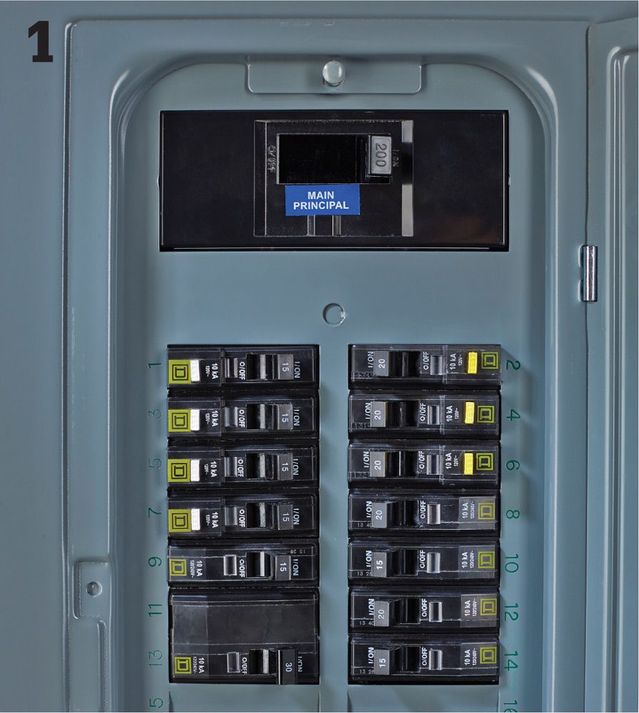
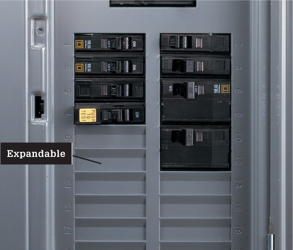
![]() Examine Your Main Service Panel
Examine Your Main Service Panel
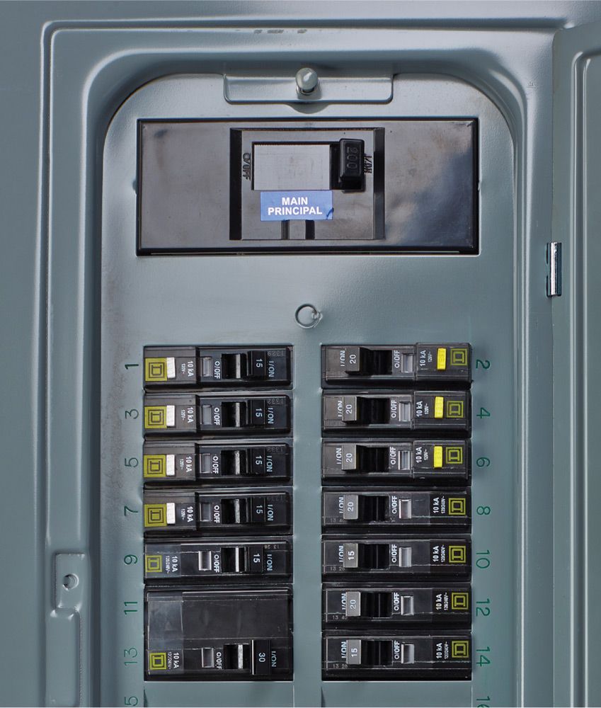
The first step in planning a new wiring project is to look in your main circuit breaker panel and find the size of the service by reading the amperage rating on the main circuit breaker. As you plan new circuits and evaluate electrical loads, knowing the size of the main service helps you determine if you need a service upgrade.
Also look for open circuit breaker slots in the panel. The number of open slots will determine if you need to add a circuit breaker subpanel.
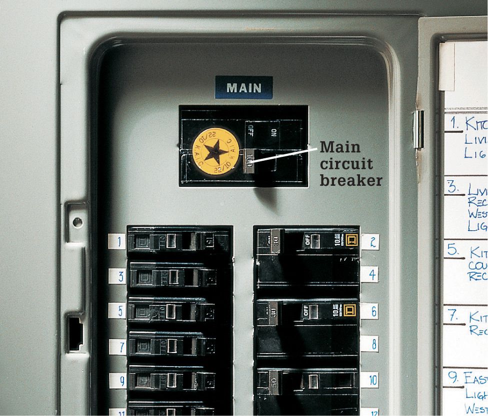
Find the service size by opening the main service panel and reading the amp rating printed on the main circuit breaker. In most cases, 100-amp service provides enough power to handle the added loads of projects such as the ones shown in this book. A service rated for 60 amps or less should be upgraded. Note: In some homes the main circuit breaker is located in a separate box.
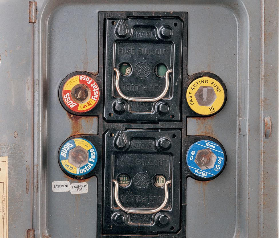
Older service panels use fuses instead of circuit breakers. Have an electrician replace this type of panel with a circuit breaker panel that provides enough power and enough open breaker slots for the new circuits you are planning.
If your main circuit breaker panel has no open breaker slots, install a subpanel (see pages 187 to 189) to provide room for connecting new circuits.
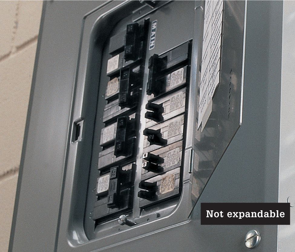
If your main circuit breaker panel has no open breaker slots, install a subpanel (see pages 187 to 189) to provide room for connecting new circuits.
![]() Learn About Codes
Learn About Codes
To ensure public safety, your community requires that you get a permit to install new wiring and have the work reviewed by an inspector. Electrical inspectors use the National Electrical Code (NEC) as the primary authority for evaluating wiring, but they also follow the local building code and electrical code standards.
Most communities use a version of the NEC that is not the most current version. Also, many communities make amendments to the NEC, and these amendments may affect your work.
As you begin planning new circuits, call or visit your local electrical inspector and discuss the project with him or her. The inspector can tell you which of the national and local code requirements apply to your job and may give you a packet of information summarizing these regulations. Later, when you apply to the inspector for a work permit, he or she will expect you to understand the local guidelines as well as a few basic NEC requirements.
The NEC is a set of standards that provides minimum safety requirements for wiring installations. It is revised every three years. The national code requirements for the projects shown in this book are thoroughly explained on the following pages. For more information, you can find copies of the current NEC, as well as a number of excellent handbooks based on the NEC, at libraries and bookstores.
In addition to being the final authority of code requirements, inspectors are electrical professionals with years of experience. Although they have busy schedules, most inspectors are happy to answer questions and help you design well-planned circuits.
![]() Basic Electrical Code Requirements
Basic Electrical Code Requirements
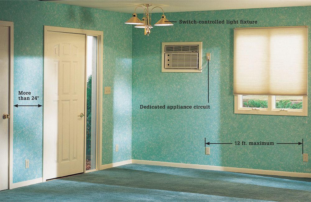
Electrical code requirements for living areas: Living areas need at least one 15-amp or 20-amp basic lighting/receptacle circuit for each 600 sq. ft. of living space and should have a dedicated circuit for each type of permanent appliance, such as an air conditioner, or a group of baseboard heaters. Receptacles on basic lighting/receptacle circuits should be spaced no more than 12 ft. apart. Many electricians and electrical inspectors recommend even closer spacing. Any wall more than 24" wide also needs a receptacle. Every room should have a wall switch at the point of entry to control either a ceiling or wall-mounted light or plug-in lamp. Kitchens and bathrooms must have a ceiling or wall-mounted light fixture.
![]() Selected NEC Standards & Tips
Selected NEC Standards & Tips
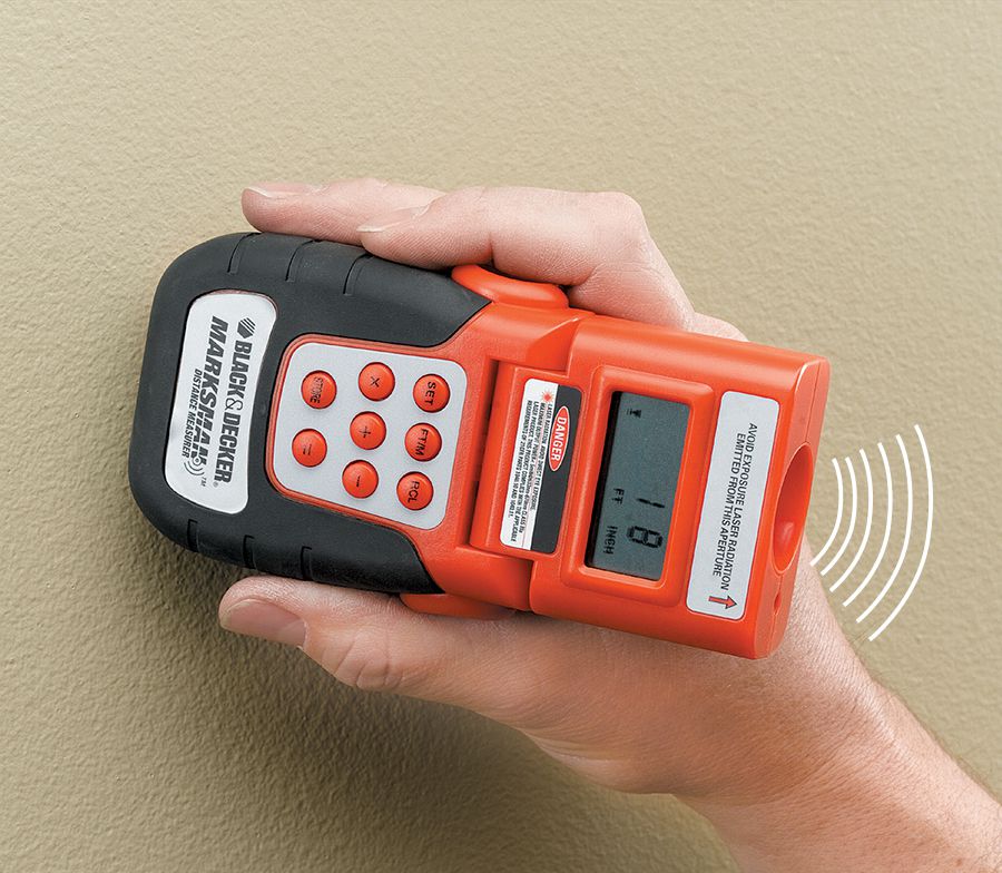
Measure the living areas of your home, excluding unconditioned spaces. A sonic measuring tool gives room dimensions quickly and contains a built-in calculator for figuring floor area. You will need a minimum of one basic lighting/receptacle circuit for every 600 sq. ft. of living space. The total square footage also helps you estimate heating and cooling needs for new room additions.
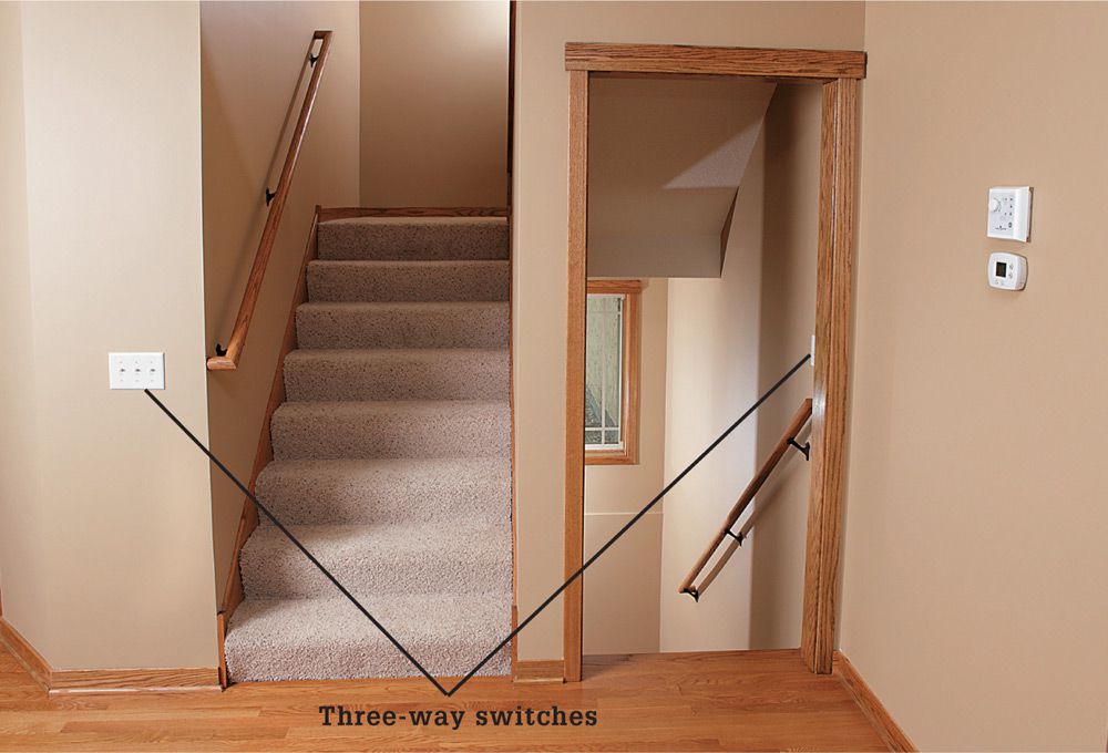
Stairways must have a light fixture near each landing, including the top and bottom landings, or must have a light fixture above each flight of stairs. The light fixture must be controlled by three-way switches at the top and bottom landings.
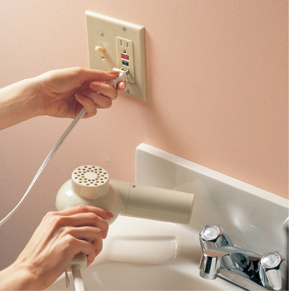
Kitchen and bathroom receptacles must be protected by a ground-fault circuit-interrupter (GFCI). Also, all outdoor receptacles and general-use receptacles in an unfinished basement or crawl space and garages must be protected by a GFCI.
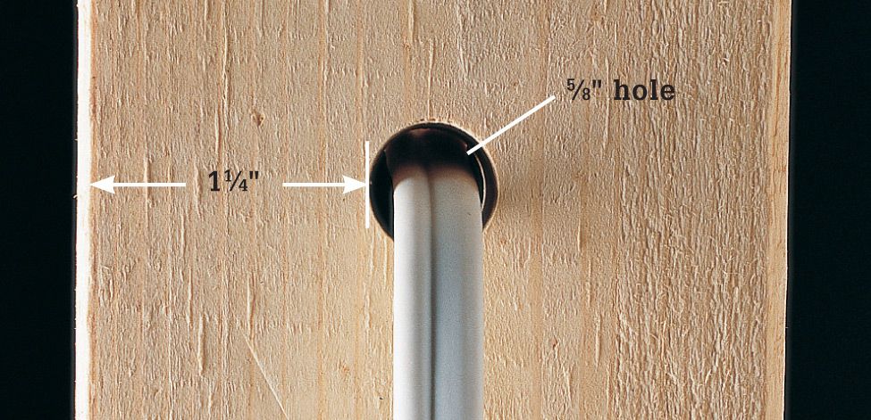

Cables must be protected against damage by nails and screws by at least 1 1/4" of wood (top). When cables pass through 2" × 2" furring strips (bottom), protect the cables with metal nail guards. Nail guards also may be used to protect cable that cannot meet the 1 1/4" of wood protection standard.
Closets and other storage spaces should have at least one light fixture that is controlled by a wall switch near the entrance. Prevent fire hazards by positioning the light fixtures so the outer globes are at least 12" away from all shelf areas. Note: This suggestion is primarily for homeowner convenience and is not required by most codes.
Hallways more than 10 ft. long need at least one receptacle. All hallways should have a switch-controlled light fixture.
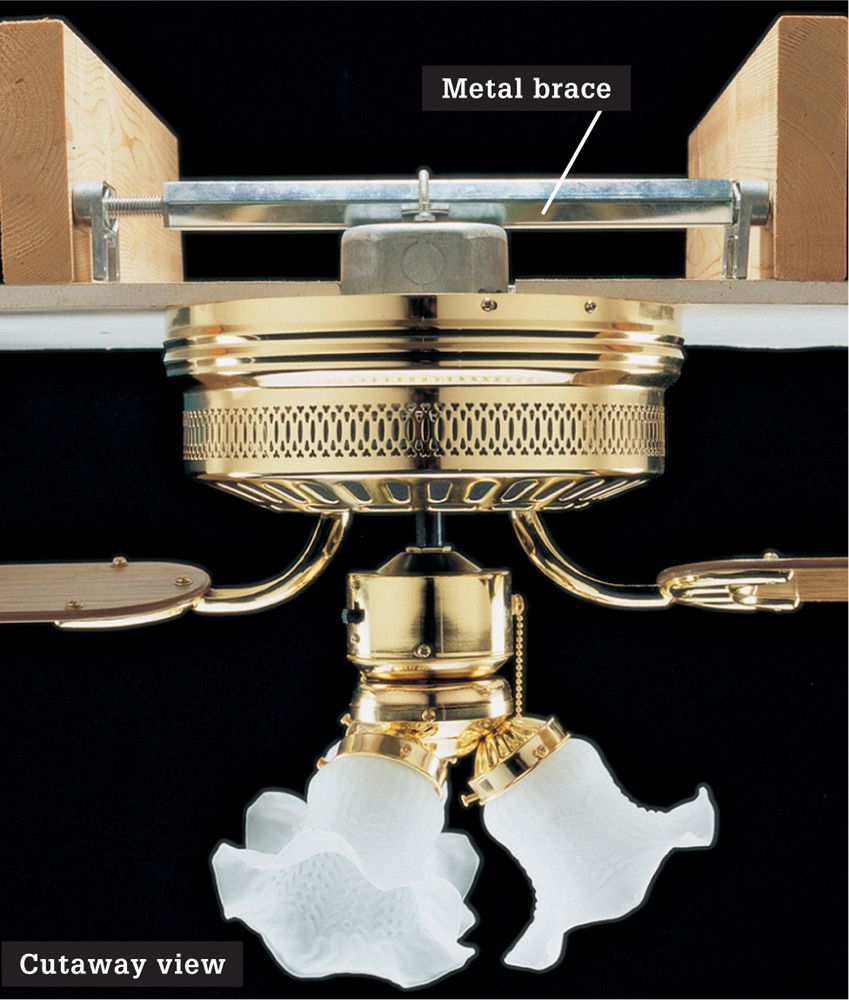
A metal brace attached to framing members is required for ceiling fans and large light fixtures that are too heavy to be supported by an electrical box. All ceiling fans must be installed in a box that is fan-rated.
Label new circuits on an index attached to the circuit breaker panel. List the rooms and appliances controlled by each circuit. Make sure the area around the panel is clean, well lighted, and accessible.
Highlights of the National Electrical Code ![]()
BY MATERIAL
Panels
✵ Maintain a minimum 30" wide by 36" deep of clearance in front of the panel.
✵ Match the amperage rating of the circuit when replacing fuses.
✵ Use handle ties on all 240-volt breakers and on 120-volt breakers protecting multi-wire branch circuits.
✵ Close all unused panel openings.
✵ Label each fuse and breaker clearly on the panel.
Electrical Boxes
✵ Use boxes that are large enough to accommodate the number of wires and devices in the box.
✵ Install all junction boxes so they remain accessible.
✵ Leave no gaps greater than 1/8" between wallboard and the front of electrical boxes.
✵ Place receptacle boxes flush with combustible surfaces.
✵ Leave a minimum of 3" of usable cable or wire extending past the front of the electrical box.
Wires & Cables
✵ Use wires that are large enough for the amperage rating of the circuit (see Wire Size Chart, page 26).
✵ Drill holes at least 2" from the edges of joists. Do not attach cables to the bottom edge of joists.
✵ Do not run cables diagonally between framing members.
✵ Use nail plates to protect cable that is run through holes drilled or cut into studs less than 1 1/4" from the front edge of a stud.
✵ Do not crimp cables sharply.
✵ Contain spliced wires or connections entirely in a plastic or metal electrical box.
✵ Use wire connectors to join wires.
✵ Use staples to fasten cables within 8" of an electrical box and every 54" along its run.
✵ Leave a minimum 1/4" (maximum 1") of sheathing where cables enter an electrical box.
✵ Clamp cables and wires to electrical boxes with approved clamps. No clamp is necessary for one-gang plastic boxes if cables are stapled within 8".
✵ Connect only a single wire to a single screw terminal. Use pigtails to join more than one wire to a screw terminal.
Switches
✵ Use a switch-controlled receptacle in rooms without a built-in light fixture operated by a wall switch.
✵ Use three-way switches at the top and bottom on stairways with six risers or more.
✵ Use switches with grounding screws with plastic electrical boxes.
✵ Locate all wall switches within easy reach of the room entrance and not behind the door.
✵ Install a neutral wire in switch boxes.
✵ Use black or red wires to supply power to switched devices.
Receptacles
✵ Install receptacles on all walls 24" wide or greater.
✵ Install receptacles so a 6-ft. cord can be plugged in from any point along a wall or every 12 ft. along a wall.
✵ Include receptacles in any hallway that is 10 ft. long or longer.
✵ Use three-slot, grounded receptacles for all 15- or 20-amp, 120-volt branch circuits.
✵ Include a switch-controlled receptacle in rooms without a built-in light fixture operated by a wall switch.
✵ Install GFCI-protected circuits in bathrooms, kitchens, garages, crawl spaces, unfinished basements, and outdoor receptacle locations.
Light Fixtures
✵ Use mounting straps that are anchored to the electrical boxes to mount ceiling fixtures.
✵ Keep non-IC-rated recessed light fixtures 3" from insulation and 1/2" from combustibles.
✵ Include at least one switch-operated lighting outlet in every room.
Grounding (page 20)
✵ Ground receptacles by connecting receptacle grounding screws to the circuit grounding wires.
✵ Use switches with grounding screws whenever possible. Always ground switches installed in plastic electrical boxes and all switches in kitchens, bathrooms, and basements.
BY ROOM
Kitchens/Dining Rooms
✵ Install at least two 20-amp small appliance receptacle circuits.
✵ Install dedicated 15-amp, 120-volt circuits for dish-washers and food disposals (required by many local codes).
✵ Install GFCI protection for all countertop receptacles; receptacles behind fixed appliances do not need to be GFCI protected.
✵ Position receptacles for appliances that will be installed within cabinets, such as microwaves or food disposals, according to the manufacturer’s instructions.
✵ Include receptacles on all counters wider than 12".
✵ Space receptacles a maximum of 48" apart above countertops and closer together in areas where many appliances will be used.
✵ Locate receptacles on the wall above the countertop not more than 20" above the countertop.
✵ Install at least one receptacle not more than 12" below the countertop on islands and peninsulas that are 12" × 24" or greater.
✵ Do not connect lights to the small appliance receptacle circuits.
✵ Install at least one wall or ceiling-mounted light fixture.
Bathrooms
✵ Install a separate 20-amp GFCI-protected circuit only for bathroom receptacles.
✵ Ground switches in bathrooms.
✵ Install at least one receptacle not more than 36" from each sink.
✵ Install at least one ceiling- or wall-mounted light fixture.
Utility/Laundry Rooms
✵ Install a separate 20-amp circuit for a washing machine.
✵ Install approved conduit for wiring in unfinished rooms.
✵ Use GFCI-protected circuits for 120-volt receptacles within 6 feet from a sink (including the washing machine receptacle).
Living, Entertainment, Bedrooms
✵ Install at least one 15- or 20-amp lighting/receptacle circuit for each 600 sq. ft. of living space.
✵ Install a dedicated circuit for each permanent appliance, such as an air conditioner or group of electric baseboard heaters.
✵ Use electrical boxes listed and labeled to support ceiling fans.
✵ Include receptacles on walls 24" wide or more.
✵ Space receptacles on walls in living and sleeping rooms a maximum of 12 ft. apart.
✵ Check with your local electrical inspector about requirements for installing smoke and carbon monoxide alarms during remodeling.
Outdoors
✵ Check for underground utilities before digging.
✵ Use UF cable or other wiring approved for wet locations for outdoor wiring.
✵ Run cable and wires in schedule 80 PVC plastic and other approved conduit, as required by local code.
✵ Install in-use rated weatherproof receptacle covers.
✵ Bury cables and wires run in conduit at least 18" deep; cable not in conduit must be buried at least 24" deep.
✵ Use weatherproof electrical boxes with watertight covers.
✵ Install GFCI-protected circuits for receptacles.
✵ Support boxes that are not attached to a building and that contain switches or receptacles using at least two pieces of conduit. Secure the conduit not more than 18 feet from the box. Locate the box at least 12" above the ground.
Stairs/Hallways
✵ Use three-way switches at the top and bottom on stairways with six risers or more.
✵ Include receptacles in any hallway that is 10 ft. long or longer.
✵ Position stairway lights so each step and landing is illuminated.
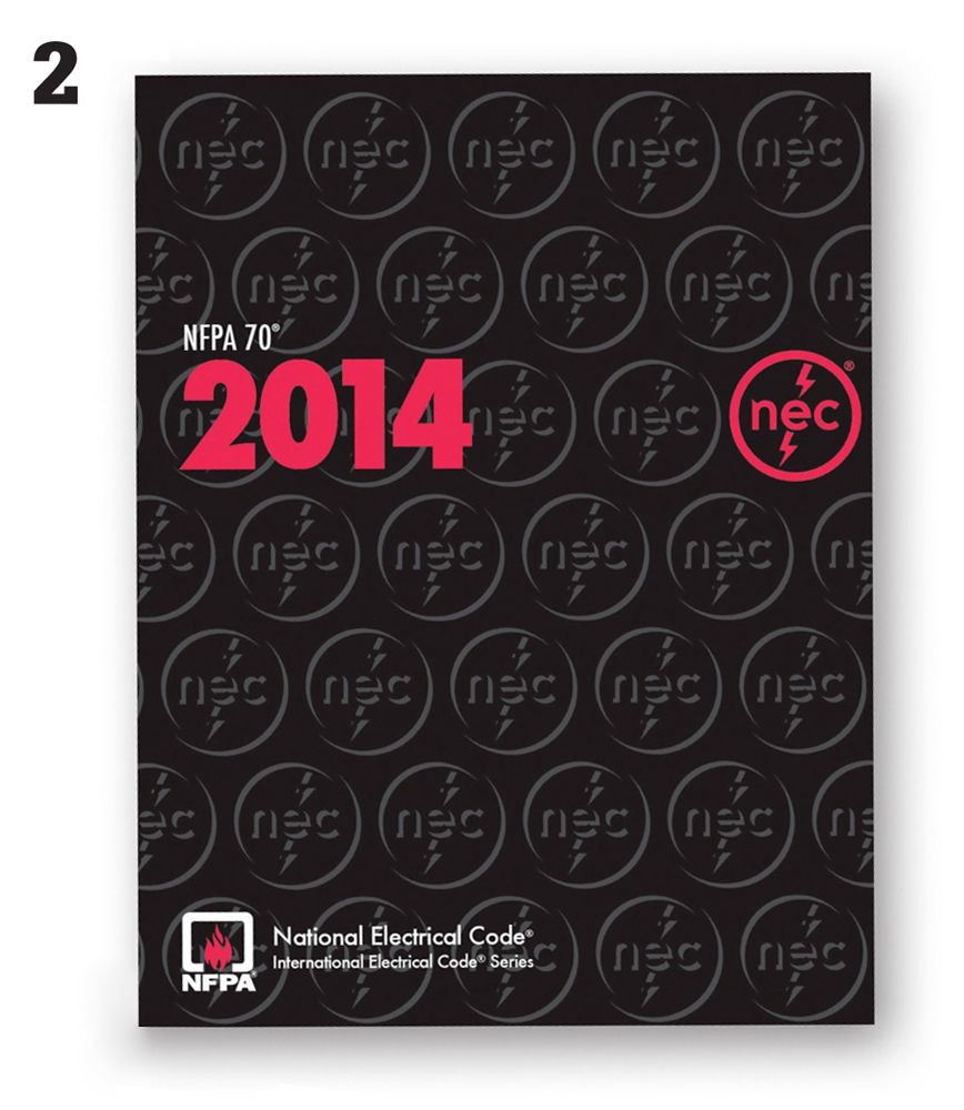
![]() Prepare for Inspections
Prepare for Inspections
Electrical inspectors who issue the work permit for your wiring project will also visit your home to review the work. Make sure to allow time for these inspections as you plan the project. For most projects, inspectors make two visits.
The first inspection, called the rough-in, is done after the cables are run between the boxes but before the insulation, wallboard, switches, and fixtures are installed. The second inspection, called the final, is done after the walls and ceilings are finished and all electrical connections are made.
When preparing for the rough-in inspection, make sure the area is neat. Sweep up sawdust and clean up any pieces of scrap wire or cable insulation. Before inspecting the boxes and cables, inspectors will check to make sure all plumbing and other mechanical work is completed. Some electrical inspectors will ask to see your building and plumbing permits.
At the final inspection, inspectors check random boxes to make sure the wire connections are correct. If they see good workmanship at the selected boxes, the inspection will be over quickly. However, if they spot a problem, inspectors may choose to inspect every connection.
Inspectors have busy schedules, so it is a good idea to arrange for an inspection several days in advance. In addition to basic compliance with code, inspectors expect your work to meet their own standards for quality. When you apply for a work permit, make sure you understand what the inspectors will look for during inspections.
You cannot put new circuits into use legally until an inspector approves them at the final inspection. If you have planned carefully and done your work well, electrical inspections are routine visits that give you confidence in your own skills.
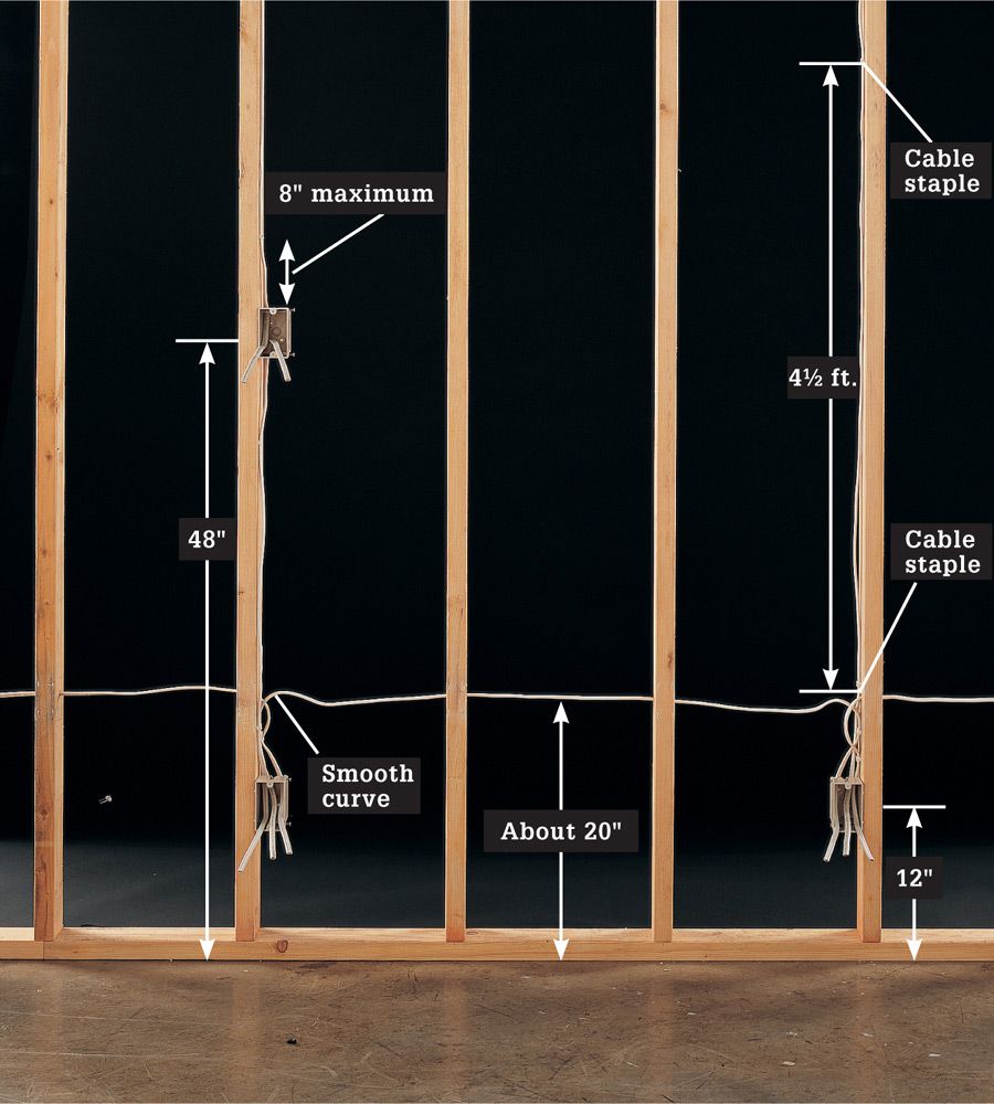
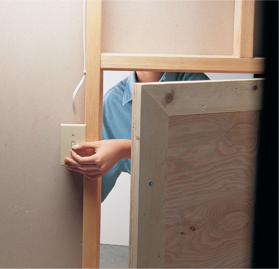
Inspectors may measure to see that electrical boxes are mounted at consistent heights. Height may not be dictated by code, but consistency is a sign of good workmanship. Measured from the center of the boxes, receptacles in living areas typically are located 12" above the finished floor and switches at 48". For special circumstances, inspectors allow you to alter these measurements. For example, you can install switches at 36" above the floor in a child’s bedroom, or set receptacles at 24" to make them more convenient for someone using a wheelchair.
Inspectors will check cables to see that they are anchored by cable staples driven within 8" of each box and every 4 1/2 ft. thereafter when they run along studs. When bending cables, form the wire in a smooth curve. Do not crimp cables sharply or install them diagonally between framing members. Some inspectors specify that cables running between receptacle boxes should be about 20" above the floor.
![]() What Inspectors Look for
What Inspectors Look for
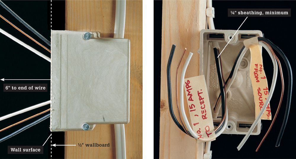
Electrical box faces should extend past the front of framing members so the boxes will be flush with finished walls (left). Inspectors will check to see that all boxes are large enough for the wires they contain. Cables should be cut and stripped back so that at least 3" of usable length extends past the front of the box and so that at least 1/4" of sheathing reaches into the box (right). Label all cables to show which circuits they serve: inspectors recognize this as a mark of careful work. The labels also simplify the final hookups after the wallboard is installed.
Is your Receptacle Spacing Correct ![]()
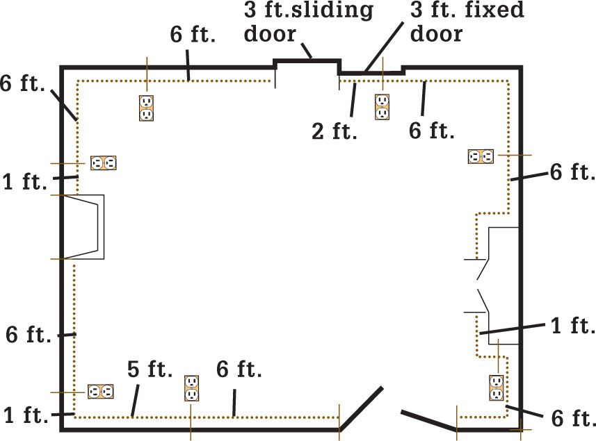
Example of receptacle spacing requirements in a typical room. Measure receptacle spacing distance along the wall line. Install receptacles along partial height walls and along balcony guards in lofts and similar areas.
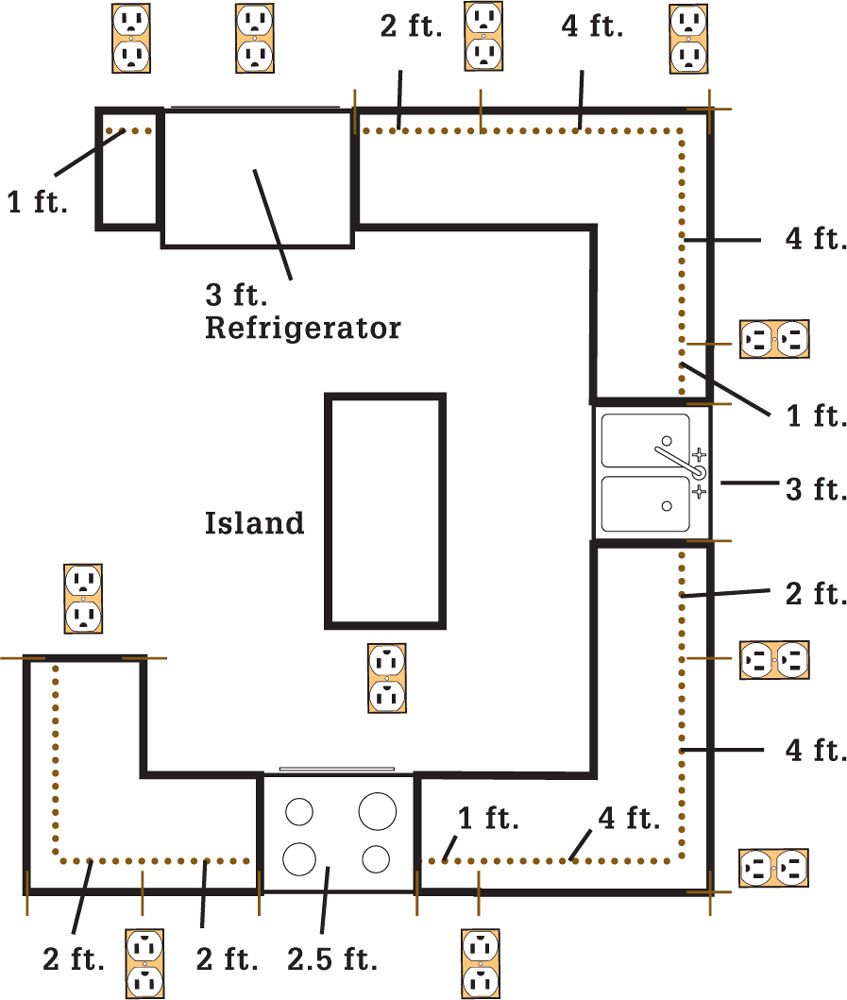
Example of countertop receptacle spacing in a typical kitchen.
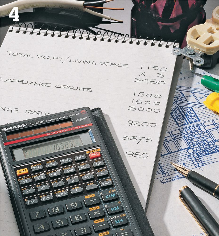
![]() Evaluate Electrical Loads
Evaluate Electrical Loads
Before drawing a plan and applying for a work permit, make sure your home’s electrical service provides enough power to handle the added load of the new circuits. In a safe wiring system, the current drawn by fixtures and appliances never exceeds the main service capacity.
To evaluate electrical loads, use the work sheet on page 137 or whatever evaluation method is recommended by your electrical inspector. Include the load for all existing wiring as well as that for proposed new wiring when making your evaluation.
Most of the light fixtures and plug-in appliances in your home are evaluated as part of general allowances for basic lighting/receptacle circuits and small-appliance circuits. However, appliances that are permanently installed require their own dedicated circuits. The electrical loads for these appliances are added in separately when evaluating wiring.
If your evaluation shows that the load exceeds the main service capacity, you must have an electrician upgrade the main service before you can install new wiring. An electrical service upgrade is a worthwhile investment that improves the value of your home and provides plenty of power for present and future wiring projects.
Amperage ![]()
|
AMPS × VOLTS |
TOTAL CAPACITY |
SAFE CAPACITY |
|
15 A × 120 V = |
1,800 watts |
1,440 watts |
|
20 A × 120 V = |
2,400 watts |
1,920 watts |
|
25 A × 120 V = |
3,000 watts |
2,400 watts |
|
30 A × 120 V = |
3,600 watts |
2,880 watts |
|
20 A × 240 V = |
4,800 watts |
3,840 watts |
|
30 A × 240 V = |
7,200 watts |
5,760 watts |
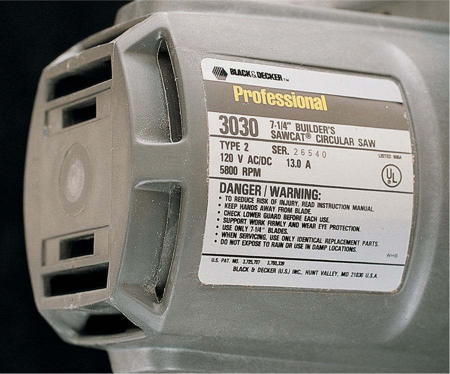
Amperage rating can be used to find the wattage of an appliance. Multiply the amperage by the voltage of the circuit. For example, a 13-amp, 120-volt circular saw is rated for 1,560 watts.
![]() Calculating Loads
Calculating Loads
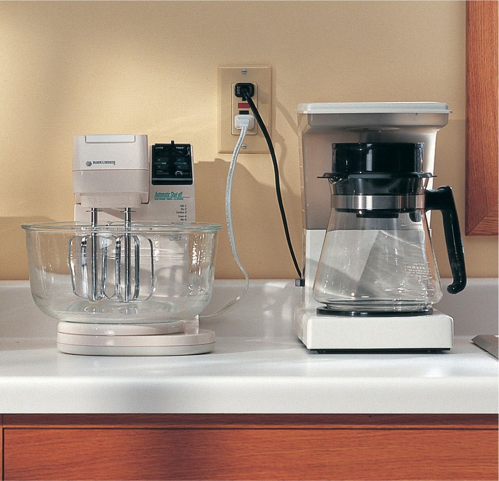
Add 1,500 watts for each small appliance circuit required by the local electrical code. In most communities, three such circuits are required—two in the kitchen and one for the laundry—for a total of 4,500 watts. No further calculations are needed for appliances that plug into small-appliance or basic lighting/receptacle circuits.
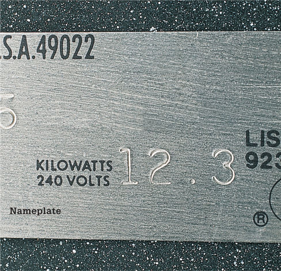
If the nameplate gives the rating in kilowatts, find the watts by multiplying kilowatts times 1,000. If an appliance lists only amps, find watts by multiplying the amps times the voltage—either 120 or 240 volts.
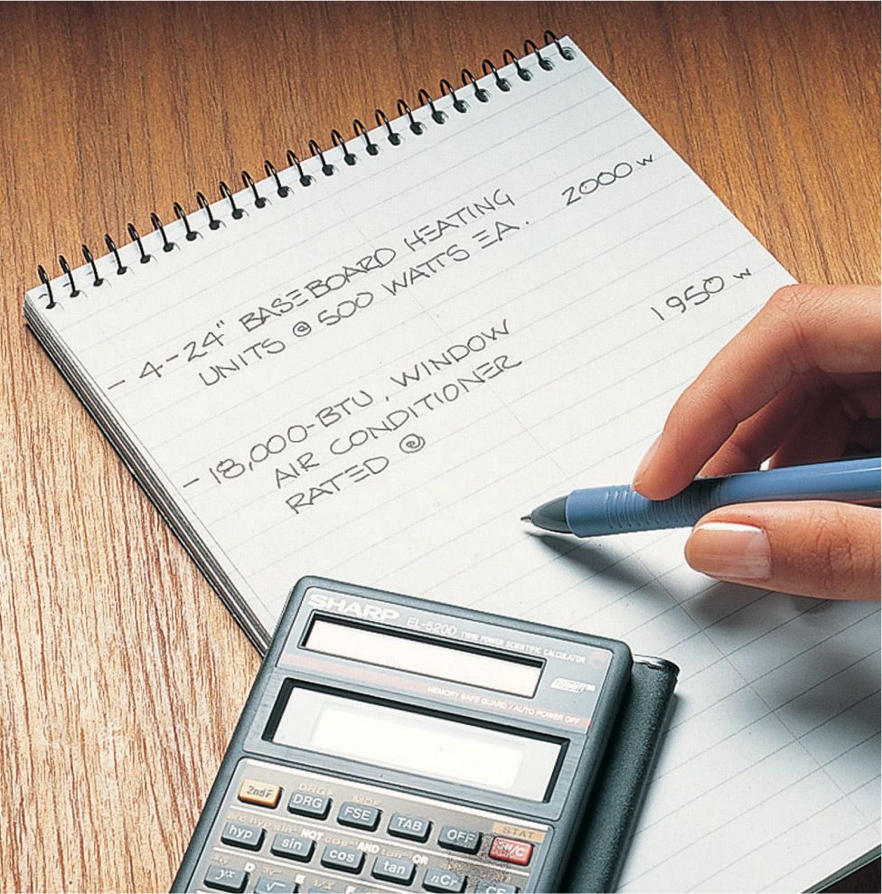
Air-conditioning and heating appliances are not used at the same time, so figure in only the larger of these two numbers when evaluating your home’s electrical load.
Fixed Devices ![]()
Do not connect one or more fixed devices that in total exceed 50 percent of a multiple outlet branch circuit’s amperage rating. Fixed devices do not include light fixtures. This means that that all fixed devices (such as a permanently wired disposal or hot water circulating pump) on a multiple outlet branch circuit may not exceed 7.5 amps (about 900 watts) on a 15-amp multiple outlet branch circuit and may not exceed 10 amps (about 1,200 watts) on a 20-amp multiple outlet branch circuit.
![]() Locating Wattage
Locating Wattage
Light bulb wattage ratings are printed on the top of the bulb. If a light fixture has more than one bulb, remember to add the wattages of all the bulbs to find the total wattage of the fixture.
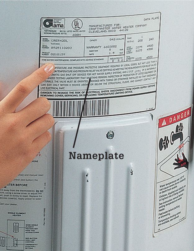
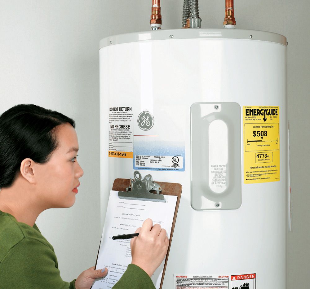
Electric water heaters are permanent appliances that require their own dedicated 30-amp, 240-volt circuits. Most water heaters are rated between 3,500 and 4,500 watts. If the nameplate lists several wattage ratings, use the one labeled “Total Connected Wattage” when figuring electrical loads.
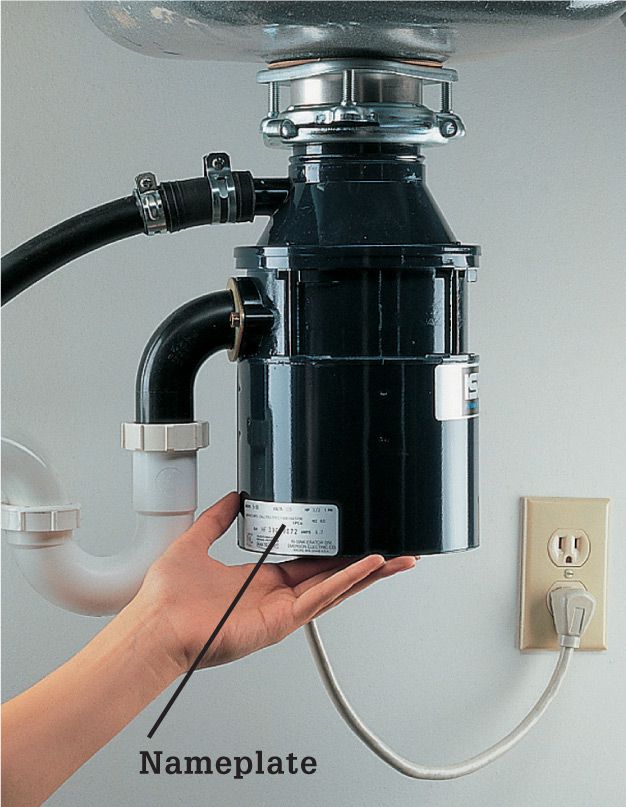
Food disposers are considered permanent appliances and may require their own dedicated 15-amp, 120-volt circuits. Most disposers are rated between 500 and 900 watts.
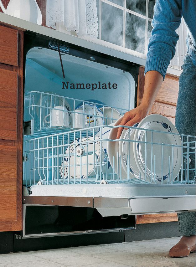
Dishwashers installed permanently under a countertop may need a dedicated 15-amp, 120-volt circuits. Dishwasher ratings are usually between 1,000 and 1,500 watts. Portable dishwashers are regarded as part of small appliance circuits and are not added in when figuring loads.

Electric ranges can be rated for as little as 3,000 watts or as much as 12,000 watts. They require dedicated 120/240-volt circuits. Find the exact wattage rating by reading the nameplate found inside the oven door or on the back of the unit.
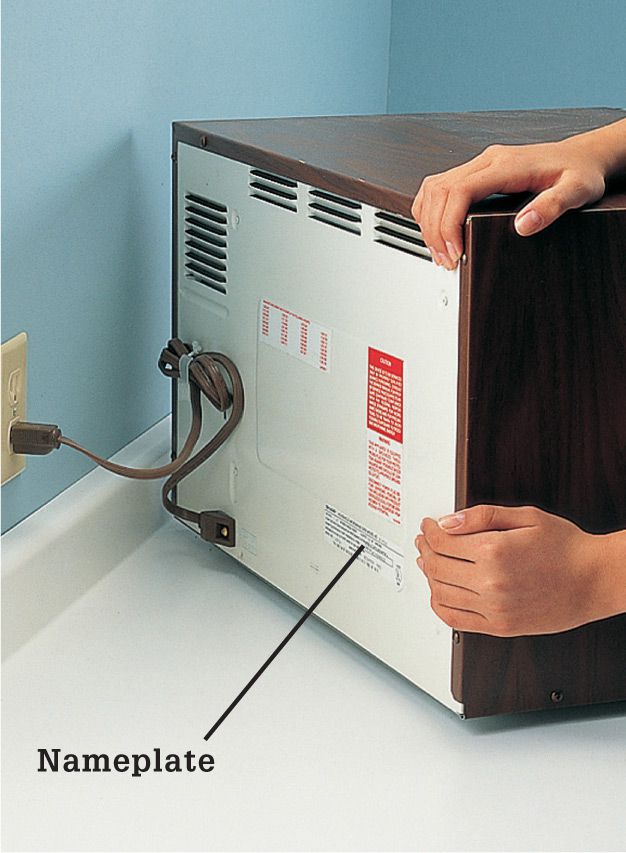
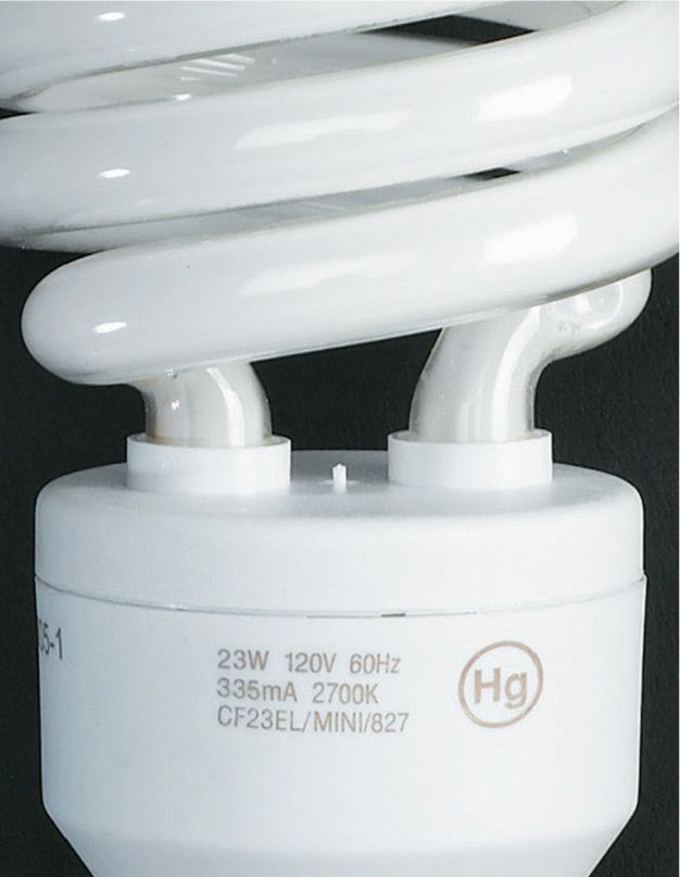
Microwave ovens are regarded as permanent appliances. Add in its wattage rating when calculating loads. The nameplate is found on the back of the cabinet or inside the front door. Most microwave ovens are rated between 500 and 1,200 watts.

Freezers are permanent appliances that may need a dedicated 15- or 20-amp, 120-volt circuits. Freezer ratings are usually between 240 and 480 watts. But combination refrigerator-freezers rated for 1,000 watts or less are plugged into small appliance circuits and do not need their own dedicated circuits. The nameplate for a freezer is found inside the door or on the back of the unit, just below the door seal.

Electric clothes dryers are permanent appliances that need dedicated 30-amp, 120/240-volt circuits. The wattage rating is printed on the nameplate inside the dryer door. Use 5,000 watts as a minimum, regardless of the printed rating. Washing machines and gas-heat clothes dryers with electric tumbler motors do not need dedicated circuits. They plug into the 20-amp small-appliance circuit in the laundry room.

Forced-air furnaces and heat pump air handlers have electric fans and are considered permanent appliances. They require dedicated 15-amp, 120-volt circuits. Include the fan wattage rating, printed on a nameplate inside the control panel, when figuring wattage loads for heating. You should also include the wattage rating for heat pump backup heating coils.
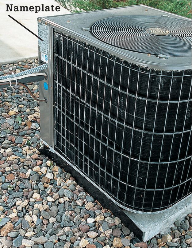
A central air conditioner requires a dedicated 240-volt circuit. Estimate its wattage rating by adding the numbers labeled RLA and FLA on the air conditioner’s metal plate. Multiply the RLA+FLA by 240.
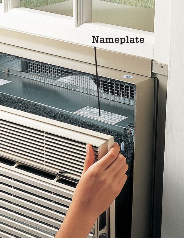
Window air conditioners, both 120-volt and 240-volt types, are permanent appliances that require dedicated circuits. The wattage rating, which can range from 500 to 2,000 watts, is found on the nameplate located inside the front grill. Make sure to include all window air conditioners in your evaluation.
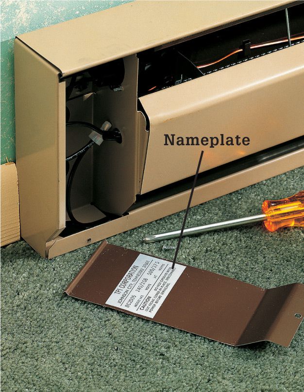
Electric room heaters that are permanently installed require a dedicated circuit and must be figured into the load calculations. Use the maximum wattage rating printed inside the cover. In general, 240-volt baseboard-type heaters are rated for 180 to 250 watts for each linear foot.
![]() Sample Circuit Evaluation
Sample Circuit Evaluation
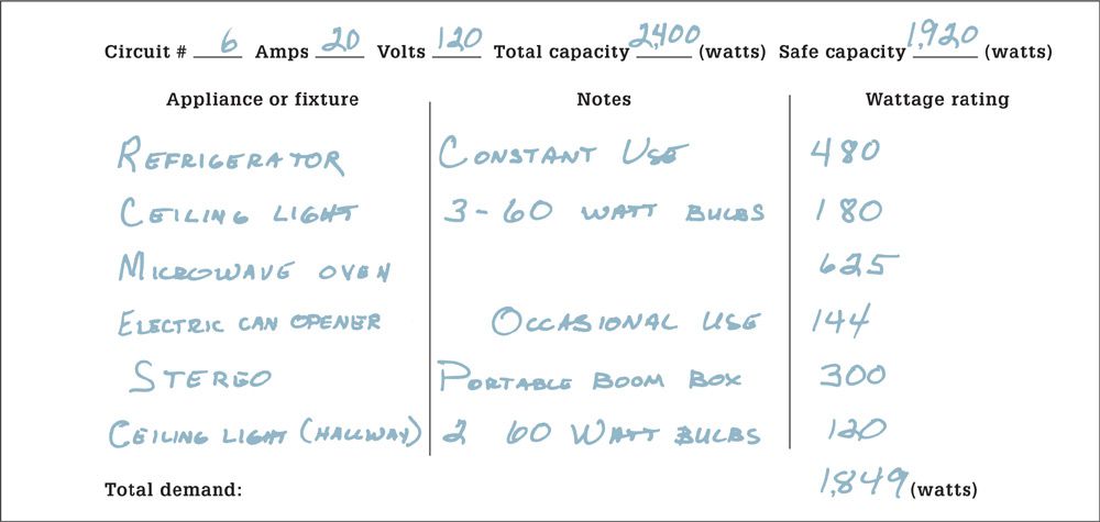
Photocopy this sample circuit evaluation to keep a record of the power demand of each circuit. The words and numbers printed in blue will not reproduce on photocopies. In this sample kitchen circuit, the demand on the circuit is very close to the safe capacity. Adding another appliance, such as an electric frying pan, could overload the circuit and cause a fuse to blow or a circuit breaker to trip.
Typical Wattage Ratings (120-volt Circuit Except Where Noted) ![]()
|
APPLIANCE |
Air conditioner (central) |
|
AMPS |
13 to 36 (240-v) |
|
WATTS |
3,120 to 8,640 |
|
APPLIANCE |
Air conditioner (window) |
|
AMPS |
6 to 13 |
|
WATTS |
720 to 1,560 |
|
APPLIANCE |
Blender |
|
AMPS |
2 to 4 |
|
WATTS |
240 to 480 |
|
APPLIANCE |
Broiler |
|
AMPS |
12.5 |
|
WATTS |
1,500 |
|
APPLIANCE |
Can opener |
|
AMPS |
1.2 |
|
WATTS |
144 |
|
APPLIANCE |
Circular saw |
|
AMPS |
10 to 12 |
|
WATTS |
1,200 to 1,440 |
|
APPLIANCE |
Clothes dryer |
|
AMPS |
16.5 to 34 (240-v) |
|
WATTS |
3,960 to 8,160 |
|
APPLIANCE |
Clothes iron |
|
AMPS |
9 |
|
WATTS |
1,080 |
|
APPLIANCE |
Coffeemaker |
|
AMPS |
4 to 8 |
|
WATTS |
480 to 960 |
|
APPLIANCE |
Computer |
|
AMPS |
4 to 7 |
|
WATTS |
480 to 840 |
|
APPLIANCE |
Dishwasher |
|
AMPS |
8.5 to 12.5 |
|
WATTS |
1,020 to 1,500 |
|
APPLIANCE |
Drill (portable) |
|
AMPS |
2 to 4 |
|
WATTS |
240 to 480 |
|
APPLIANCE |
DVD player |
|
AMPS |
2.5 to 4 |
|
WATTS |
300 to 480 |
|
APPLIANCE |
Fan (ceiling) |
|
AMPS |
3.5 |
|
WATTS |
420 |
|
APPLIANCE |
Fan (portable) |
|
AMPS |
2 |
|
WATTS |
240 |
|
APPLIANCE |
Freezer |
|
AMPS |
2 to 4 |
|
WATTS |
240 to 600 |
|
APPLIANCE |
Frying pan |
|
AMPS |
9 |
|
WATTS |
1,080 |
|
APPLIANCE |
Furnace, forced-air gas |
|
AMPS |
6.5 to 13 |
|
WATTS |
780 to 1,560 |
|
APPLIANCE |
Garbage disposer |
|
AMPS |
3.5 to 7.5 |
|
WATTS |
420 to 900 |
|
APPLIANCE |
Hair dryer |
|
AMPS |
5 to 10 |
|
WATTS |
600 to 1,200 |
|
APPLIANCE |
Heater (portable) |
|
AMPS |
7 to 12 |
|
WATTS |
840 to 1,440 |
|
APPLIANCE |
Microwave oven |
|
AMPS |
4 to 10 |
|
WATTS |
480 to 1,200 |
|
APPLIANCE |
Range (oven/stove) |
|
AMPS |
5.5 to 10.8 (240-v) |
|
WATTS |
1,320 to 2,600 |
|
APPLIANCE |
Refrigerator |
|
AMPS |
2 to 4 |
|
WATTS |
240 to 600 |
|
APPLIANCE |
Router |
|
AMPS |
8 |
|
WATTS |
960 |
|
APPLIANCE |
Sander (portable) |
|
AMPS |
2 to 5 |
|
WATTS |
240 to 600 |
|
APPLIANCE |
Saw (table) |
|
AMPS |
7 to 10 |
|
WATTS |
840 to 1,200 |
|
APPLIANCE |
Sewing machine |
|
AMPS |
1 |
|
WATTS |
120 |
|
APPLIANCE |
Stereo |
|
AMPS |
2.5 to 4 |
|
WATTS |
300 to 480 |
|
APPLIANCE |
Television |
|
AMPS |
2.5 |
|
WATTS |
300 |
|
APPLIANCE |
Toaster |
|
AMPS |
9 |
|
WATTS |
1,080 |
|
APPLIANCE |
Trash compactor |
|
AMPS |
4 to 8 |
|
WATTS |
480 to 960 |
|
APPLIANCE |
Vacuum cleaner |
|
AMPS |
6 to 11 |
|
WATTS |
720 to 1,320 |
|
APPLIANCE |
Waffle iron |
|
AMPS |
7.5 |
|
WATTS |
900 |
|
APPLIANCE |
Washing machine |
|
AMPS |
12.5 |
|
WATTS |
1,500 |
|
APPLIANCE |
Water heater (elec.) |
|
AMPS |
15.8 to 21 (240-v) |
|
WATTS |
3,800 to 5,040 |
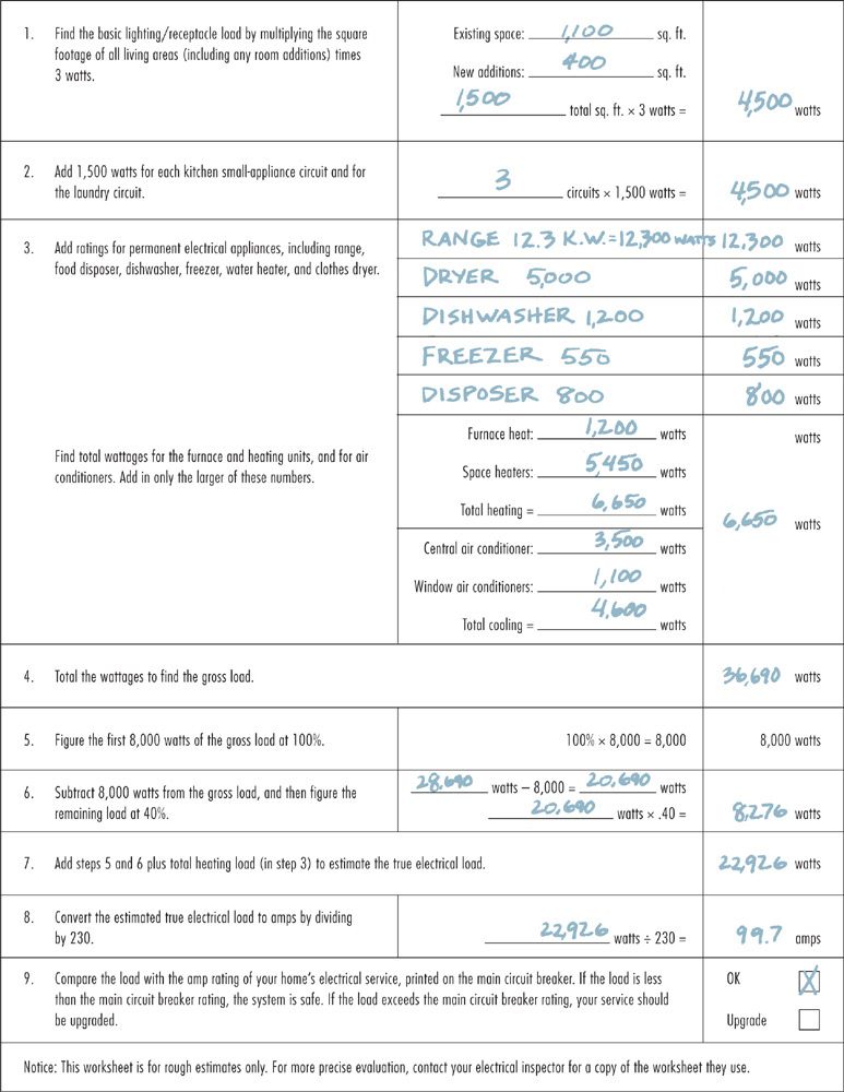
![]() How to Estimate Electrical Loads—with sample numbers
How to Estimate Electrical Loads—with sample numbers
![]() Draw a Diagram & Obtain a Permit
Draw a Diagram & Obtain a Permit
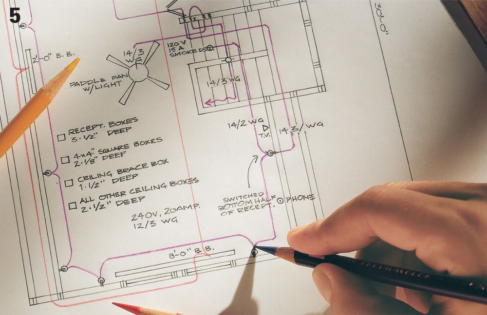
Drawing a wiring diagram is the last step in planning a circuit installation. A detailed wiring diagram helps you get a work permit, makes it easy to create a list of materials, and serves as a guide for laying out circuits and installing cables and fixtures. Use the circuit maps on pages 148 to 165 as a guide for planning wiring configurations and cable runs. Bring the diagram and materials list when you visit electrical inspectors to apply for a work permit.
Never install new wiring without following your community’s permit and inspection procedure. A work permit is not expensive, and it ensures that your work will be reviewed by a qualified inspector. If you install new wiring without the proper permit, an accident or fire traced to faulty wiring could cause your insurance company to discontinue your policy and can hurt the resale value of your home.
When electrical inspectors look over your wiring diagram, they will ask questions to see if you have a basic understanding of the electrical code and fundamental wiring skills. Some inspectors ask these questions informally, while others give a short written test. Inspectors may allow you to do some, but not all, of the work. For example, they may ask that all final circuit connections at the circuit breaker panel be made by a licensed electrician, while allowing you to do all other work.
A few communities allow you to install wiring only when supervised by an electrician. This means you can still install your own wiring but must hire an electrician to apply for the work permit and to check your work before inspectors review it. The electrician is held responsible for the quality of the job.
Remember that it is the inspectors’ responsibility to help you do a safe and professional job. Feel free to call them with questions about wiring techniques or materials.
A detailed wiring diagram and a list of materials is required before electrical inspectors will issue a work permit. If blueprints exist for the space you are remodeling, start your electrical diagram by tracing the wall outlines from the blueprint. Use standard electrical symbols (next page) to clearly show all the receptacles, switches, light fixtures, and permanent appliances. Make a copy of the symbol key and attach it to the wiring diagram for the inspectors’ convenience. Show each cable run, and label its wire size and circuit amperage.
![]() How to Draw a Wiring Plan
How to Draw a Wiring Plan
Draw a scaled diagram of the space you will be wiring, showing walls, doors, windows, plumbing pipes and fixtures, and heating and cooling ducts. Find the floor space by multiplying room length by width, and indicate this on the diagram.
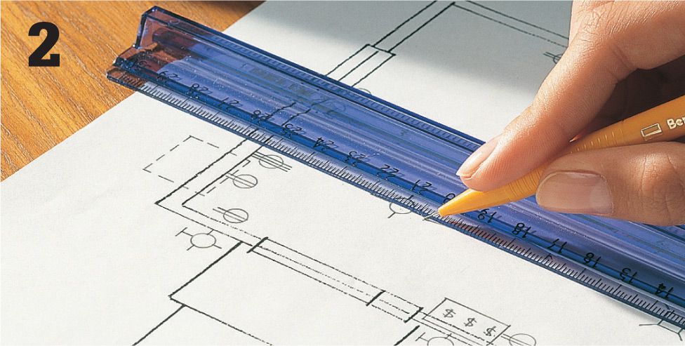
Mark the location of all switches, receptacles, light fixtures, and permanent appliances, using the electrical symbols shown below. Where you locate these devices along the cable run determines how they are wired. Use the circuit maps on pages 148 to 165 as a guide for drawing wiring diagrams.

Draw in cable runs between devices. Indicate cable size and type and the amperage of the circuits. Use a different-colored pencil for each circuit.
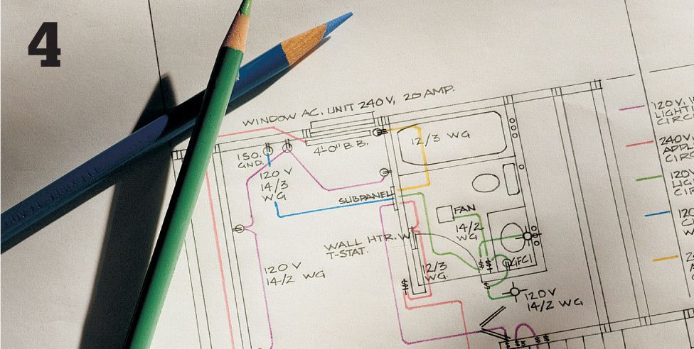
Identify the wattages for light fixtures and permanent appliances and the type and size of each electrical box. On another sheet of paper, make a detailed list of all materials you will use.
Electrical Symbol Key ![]()
(copy this key and attach it to your wiring plan)
|
|
240-volt receptacle |
|
|
Isolated ground receptacle |
|
|
Duplex receptacle |
|
|
240-volt dryer receptacle |
|
|
Singleplex receptacle |
|
|
Fourplex receptacle |
|
|
GFCI duplex receptacle |
|
|
Switched receptacle |
|
|
Weatherproof receptacle |
|
|
Thermostat |
|
|
Pilot-light switch |
|
|
Single-pole switch |
|
|
Timer switch |
|
|
Three-way switch |
|
|
Junction box |
|
|
Ceiling pull switch |
|
|
Surface-mounted light fixture |
|
|
Recessed light fixture |
|
|
Fluorescent light fixture |
|
|
Wall-mounted light fixture |
|
|
Weatherproof light fixture |
|
|
Ceiling fan |
|
|
Electric door opener |
|
|
Low-voltage transformer |
|
|
Television jack |
|
|
Telephone outlet |
|
|
Smoke dectector |
|
|
Vent fan |


![]() Wiring a Room Addition
Wiring a Room Addition
The photo below shows the circuits you would likely want to install in a large room addition. This example shows the framing and wiring of an unfinished attic converted to an office or entertainment room with a bathroom. This room includes a subpanel and five new circuits plus telephone and cable-TV lines.
A wiring project of this sort is a potentially complicated undertaking that can be made simpler by breaking the project into convenient steps, and finishing one step before moving on to the next. Turn to pages 142 to 143 to see this project represented as a wiring diagram.
Individual Circuits
![]() #1: Bathroom circuit. This 20-amp dedicated circuit supplies power to bathroom lights and fans, as well as receptacles that must be GFCI-protected at the box or at the receptacle. As with small appliance circuits in the kitchen, you may not tap into this circuit to feed any additional loads.
#1: Bathroom circuit. This 20-amp dedicated circuit supplies power to bathroom lights and fans, as well as receptacles that must be GFCI-protected at the box or at the receptacle. As with small appliance circuits in the kitchen, you may not tap into this circuit to feed any additional loads.
![]() #2: Computer circuit. A15-amp dedicated circuit with isolated ground is recommended, but an individual branch circuit is all that is required by most codes.
#2: Computer circuit. A15-amp dedicated circuit with isolated ground is recommended, but an individual branch circuit is all that is required by most codes.
Circuit breaker subpanel receives power through a 10-gauge, three-wire feeder cable connected to a 30-amp, 240-volt circuit breaker at the main circuit breaker panel. Larger room additions may require a 60-or 100-amp feeder circuit breaker.
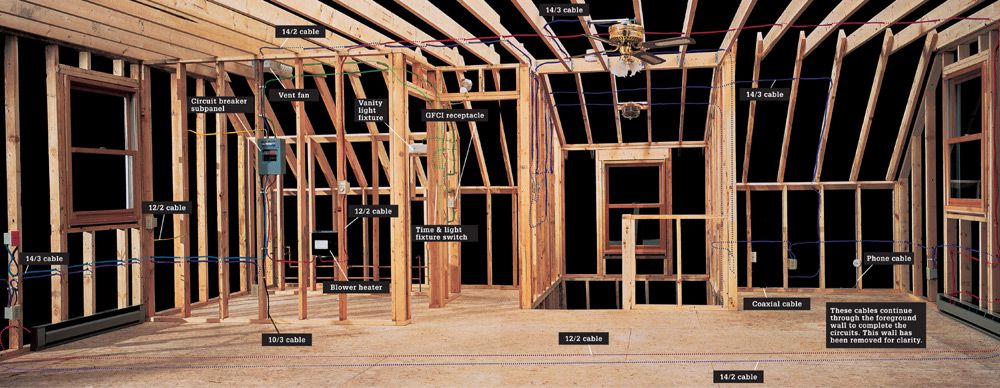
![]() #3: Air-conditioner circuit. This is a 20-amp, 240-volt dedicated circuit. In cooler climates, or in a smaller room, you may need an air conditioner and circuit rated for only 120 volts.
#3: Air-conditioner circuit. This is a 20-amp, 240-volt dedicated circuit. In cooler climates, or in a smaller room, you may need an air conditioner and circuit rated for only 120 volts.
![]() #4: Basic lighting/receptacle circuit. This 15-amp, 120-volt circuit supplies power to most of the fixtures in the bedroom and study areas.
#4: Basic lighting/receptacle circuit. This 15-amp, 120-volt circuit supplies power to most of the fixtures in the bedroom and study areas.
![]() #5: Heater circuit. This 20-amp, 240-volt circuit supplies power to the bathroom blower-heater and to the baseboard heaters. Depending on the size of your room and the wattage rating of the baseboard heaters, you may need a 30-amp, 240-volt heating circuit.
#5: Heater circuit. This 20-amp, 240-volt circuit supplies power to the bathroom blower-heater and to the baseboard heaters. Depending on the size of your room and the wattage rating of the baseboard heaters, you may need a 30-amp, 240-volt heating circuit.
Telephone outlet is wired with 22-gauge four-wire phone cable. If your home phone system has two or more separate lines, you may need to run a cable with eight wires, commonly called four-pair cable.
Cable television jack is wired with coaxial cable running from an existing television junction in the utility area.
![]() Diagram View
Diagram View
The diagram below shows the layout of the five circuits and the locations of their receptacles, switches, fixtures, and devices as shown in the photo on the previous pages. The circuits and receptacles are based on the needs of a 400-sq.-ft. space. An inspector will want to see a diagram like this one before issuing a permit. After you’ve received approval for your addition, the wiring diagram will serve as your guide as you complete your project.
![]() Circuit #1: A 20-amp, 120-volt circuit serving the bathroom and closet area. Includes: 1 2/2 NM cable, double-gang box, timer switch, single-pole switch, 4" × 4" box with single-gang adapter plate, two plastic light fixture boxes, vanity light fixture, closet light fixture, 15-amp single-pole circuit breaker.
Circuit #1: A 20-amp, 120-volt circuit serving the bathroom and closet area. Includes: 1 2/2 NM cable, double-gang box, timer switch, single-pole switch, 4" × 4" box with single-gang adapter plate, two plastic light fixture boxes, vanity light fixture, closet light fixture, 15-amp single-pole circuit breaker.
![]() Circuit #2: A 15-amp, 120-volt computer circuit. Includes: 14/2 NM cable, single-gang box, 15-amp receptacle, 15-amp single-pole circuit breaker.
Circuit #2: A 15-amp, 120-volt computer circuit. Includes: 14/2 NM cable, single-gang box, 15-amp receptacle, 15-amp single-pole circuit breaker.
![]() Circuit #3: A 20-amp, 240-volt air-conditioner circuit. Includes: 1 2/2 NM cable; single-gang box; 20-amp, 240-volt receptacle (singleplex style); 20-amp double-pole circuit.
Circuit #3: A 20-amp, 240-volt air-conditioner circuit. Includes: 1 2/2 NM cable; single-gang box; 20-amp, 240-volt receptacle (singleplex style); 20-amp double-pole circuit.

![]() Circuit #4: A 15-amp, 120-volt basic lighting/receptacle circuit serving most of the fixtures in the bedroom and study areas. Includes: 14/2 and 1 4/3 NM cable, two double-gang boxes, fan speed-control switch, dimmer switch, single-pole switch, two three-way switches, two plastic light fixture boxes, light fixture for stairway, smoke detector, metal light fixture box with brace bar, ceiling fan with light fixture, 10 single-gang boxes, 4" × 4" box with single-gang adapter plate, 10 duplex receptacles (15-amp), 15-amp single-pole circuit breaker.
Circuit #4: A 15-amp, 120-volt basic lighting/receptacle circuit serving most of the fixtures in the bedroom and study areas. Includes: 14/2 and 1 4/3 NM cable, two double-gang boxes, fan speed-control switch, dimmer switch, single-pole switch, two three-way switches, two plastic light fixture boxes, light fixture for stairway, smoke detector, metal light fixture box with brace bar, ceiling fan with light fixture, 10 single-gang boxes, 4" × 4" box with single-gang adapter plate, 10 duplex receptacles (15-amp), 15-amp single-pole circuit breaker.
![]() Circuit #5: A 20-amp, 240-volt circuit that supplies power to three baseboard heaters controlled by a wall thermostat and to a bathroom blower-heater controlled by a built-in thermostat. Includes: 1 2/2 NM cable, 750-watt blower heater, single-gang box, line-voltage thermostat, three baseboard heaters, 20-amp double-pole circuit breaker.
Circuit #5: A 20-amp, 240-volt circuit that supplies power to three baseboard heaters controlled by a wall thermostat and to a bathroom blower-heater controlled by a built-in thermostat. Includes: 1 2/2 NM cable, 750-watt blower heater, single-gang box, line-voltage thermostat, three baseboard heaters, 20-amp double-pole circuit breaker.
 Cable television jack: Coaxial cable with F-connectors, signal splitter, cable television outlet with mounting brackets.
![]() Circuit #6: A 20-amp, 120-volt, GFCI-protected bathroom receptacle circuit for the bathroom. Includes GFCI breaker, 1 2/2 NM cable, boxes, and 20-amp receptacles.
Circuit #6: A 20-amp, 120-volt, GFCI-protected bathroom receptacle circuit for the bathroom. Includes GFCI breaker, 1 2/2 NM cable, boxes, and 20-amp receptacles.
![]() Wiring a Kitchen
Wiring a Kitchen
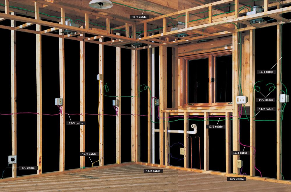
The photo at left shows the circuits you would probably want to install in a total kitchen remodel. Kitchens require a wide range of electrical services, from simple 15-amp lighting circuits to 120/240, 50-amp appliance circuits. This kitchen example has seven circuits, including separate dedicated circuits for a dishwasher and food disposer. Some codes allow the disposer and dishwasher to share a single circuit.
All rough carpentry and plumbing should be in place before beginning any electrical work. As always, divide a project of this scale into manageable steps, and finish one step before moving on. Turn to pages 146 to 147 to see this project represented as a wiring diagram.
Individual Circuits
![]() #1 & #2: Small-appliance circuits. Two 20-amp, 120-volt circuits supply power to countertop and eating areas for small appliances. All general-use receptacles must be on these circuits. One 1 2/3 cable fed by a 20-amp double-pole breaker wires both circuits. These circuits share one electrical box with the disposer circuit (#5) and another with the basic lighting circuit (#7). Other circuits may also service the area, as with a dedicated refrigerator circuit.
#1 & #2: Small-appliance circuits. Two 20-amp, 120-volt circuits supply power to countertop and eating areas for small appliances. All general-use receptacles must be on these circuits. One 1 2/3 cable fed by a 20-amp double-pole breaker wires both circuits. These circuits share one electrical box with the disposer circuit (#5) and another with the basic lighting circuit (#7). Other circuits may also service the area, as with a dedicated refrigerator circuit.
![]() #3: Range circuit. A 40- or 50-amp, 120/240-volt dedicated circuit supplies power to the range/oven appliance. It is wired with 6/3 copper cable.
#3: Range circuit. A 40- or 50-amp, 120/240-volt dedicated circuit supplies power to the range/oven appliance. It is wired with 6/3 copper cable.
![]() #4: Microwave circuit. It is wired with 1 2/2 cable. Microwaves that use less than 300 watts can be installed on a 15-amp circuit or plugged into the small-appliance circuits.
#4: Microwave circuit. It is wired with 1 2/2 cable. Microwaves that use less than 300 watts can be installed on a 15-amp circuit or plugged into the small-appliance circuits.
![]() #5: Food disposer/dishwasher circuit. A dedicated 15-amp, 120-volt circuit supplies power to the disposer. It is wired with 14/2 cable. Some local codes may allow the disposer to be on the same circuit as the dishwasher if it is a 20-amp circuit.
#5: Food disposer/dishwasher circuit. A dedicated 15-amp, 120-volt circuit supplies power to the disposer. It is wired with 14/2 cable. Some local codes may allow the disposer to be on the same circuit as the dishwasher if it is a 20-amp circuit.
![]() #6: Basic lighting circuit. A 15-amp, 120-volt circuit powers the ceiling fixture, recessed fixtures, and undercabinet task lights. 14/2 and 1 4/3 cables connect the fixtures and switches in the circuit. Each task light has a self-contained switch.
#6: Basic lighting circuit. A 15-amp, 120-volt circuit powers the ceiling fixture, recessed fixtures, and undercabinet task lights. 14/2 and 1 4/3 cables connect the fixtures and switches in the circuit. Each task light has a self-contained switch.
![]() Diagram View
Diagram View
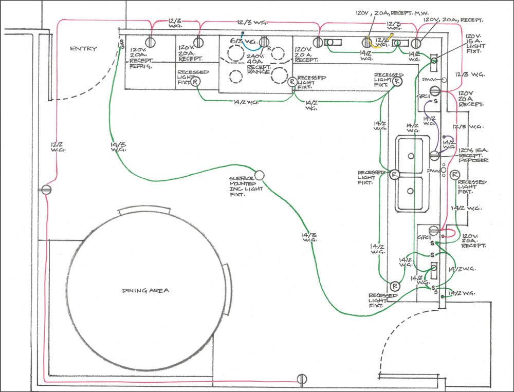
The diagram at left shows the layout of the seven circuits and the locations of their receptacles, switches, fixtures, and devices as shown in the photo on the previous pages. The circuits and receptacles are based on the needs of a 175-sq.-ft. space kitchen. An inspector will want to see a diagram like this one before issuing a permit. After you’ve received approval for your addition, the wiring diagram will serve as your guide as you complete your project.
![]() Circuits #1 & #2: Two 20-amp, 120-volt small-appliance circuits wired with one cable. All general-use receptacles must be on these circuits, and they must be GFCI units. Includes: two GFCI receptacles rated for 20 amps, five electrical boxes that are 4" × 4", and 1 2/3 cable.
Circuits #1 & #2: Two 20-amp, 120-volt small-appliance circuits wired with one cable. All general-use receptacles must be on these circuits, and they must be GFCI units. Includes: two GFCI receptacles rated for 20 amps, five electrical boxes that are 4" × 4", and 1 2/3 cable.
![]() Circuit #3: A 50-amp, 120/240-volt dedicated circuit for the range. Includes: a 4" × 4" box; a 120/240-volt, 50-amp range receptacle; and 6/3 NM copper cable.
Circuit #3: A 50-amp, 120/240-volt dedicated circuit for the range. Includes: a 4" × 4" box; a 120/240-volt, 50-amp range receptacle; and 6/3 NM copper cable.
![]() Circuit #4: A 20-amp, 120-volt dedicated circuit for the microwave. Includes: a 20-amp duplex receptacle, a single-gang box, and 1 2/2 NM cable.
Circuit #4: A 20-amp, 120-volt dedicated circuit for the microwave. Includes: a 20-amp duplex receptacle, a single-gang box, and 1 2/2 NM cable.
![]() Circuit #5: A 15-amp, 120-volt dedicated circuit for the food disposer. Includes: a 15-amp duplex receptacle, a single-pole switch (installed in a double-gang box with a GFCI receptacle from the small-appliance circuits), one single-gang box, and 14/2 cable.
Circuit #5: A 15-amp, 120-volt dedicated circuit for the food disposer. Includes: a 15-amp duplex receptacle, a single-pole switch (installed in a double-gang box with a GFCI receptacle from the small-appliance circuits), one single-gang box, and 14/2 cable.
![]() Circuit #6: A 15-amp, 120-volt basic lighting circuit serving all of the lighting needs in the kitchen. Includes: two single-pole switches, two three-way switches, single-gang box, 4" × 4" box, triple-gang box (shared with one of the GFCI receptacles from the small-appliance circuits), plastic light fixture box with brace, ceiling light fixture, four fluorescent undercabinet light fixtures, six recessed light fixtures, 14/2 and 1 4/3 cables.
Circuit #6: A 15-amp, 120-volt basic lighting circuit serving all of the lighting needs in the kitchen. Includes: two single-pole switches, two three-way switches, single-gang box, 4" × 4" box, triple-gang box (shared with one of the GFCI receptacles from the small-appliance circuits), plastic light fixture box with brace, ceiling light fixture, four fluorescent undercabinet light fixtures, six recessed light fixtures, 14/2 and 1 4/3 cables.