The Complete Guide to Wiring, Updated 6th Edition: Current with 2014-2017 Electrical Codes - Black & Decker, Cool Springs Press (2014)
Chapter 7. Circuit Maps
The circuit maps on the following pages show the most common wiring variations for typical electrical devices. Most new wiring you install will match one or more of the maps shown. Find the maps that match your situation and use them to plan your circuit layouts.
The 120-volt circuits shown on the following pages are wired for 15 amps using 14-gauge wire and receptacles rated at 15 amps. If you are installing a 20-amp circuit, substitute 12-gauge cables and use receptacles rated for 15 or 20 amps.
In configurations where a white wire serves as a hot wire instead of a neutral, both ends of the wire are coded with black tape to identify it as hot. In addition, each of the circuit maps shows a box grounding screw. This grounding screw is required in all metal boxes, but plastic electrical boxes do not need to be grounded.
You should remember two new code requirements when wiring switches. (1) Provide a neutral wire at every switch box. This may require using 3-wire cable or two 2-wire cables where you may have used one 2-wire cable in the past. (2) Use a black or red wire to supply power from a switch to a light or switched receptacle.
Note: For clarity, all grounding conductors in the circuit maps are colored green. In practice, the grounding wires inside sheathed cables usually are bare copper.
In this chapter:
![]() Common Household Circuits
Common Household Circuits
![]() Common Household Circuits
Common Household Circuits
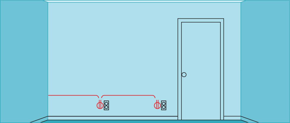
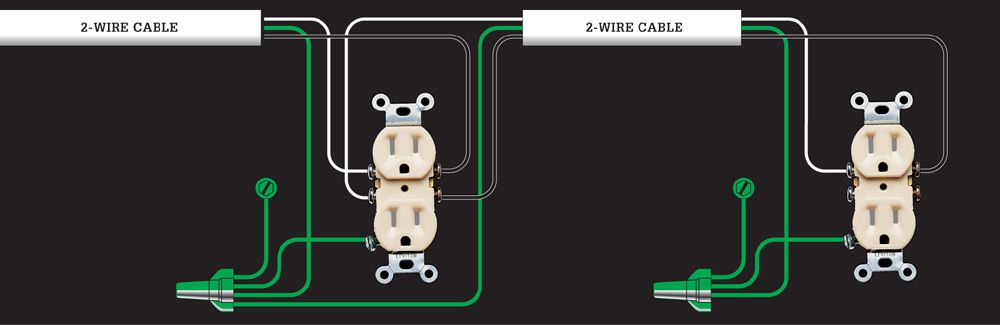
1. 120-VOLT DUPLEX RECEPTACLES WIRED IN SEQUENCE
Use this layout to link any number of duplex receptacles in a basic lighting/receptacle circuit. The last receptacle in the cable run is connected like the receptacle shown at the right side of the circuit map below. All other receptacles are wired like the receptacle shown on the left side. This configuration or layout requires two-wire cables.
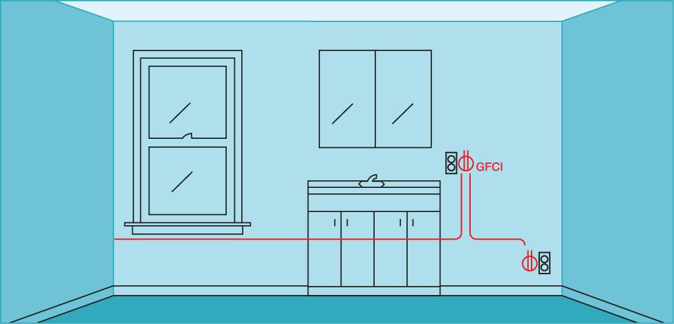
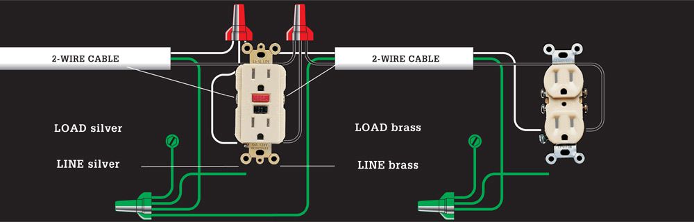
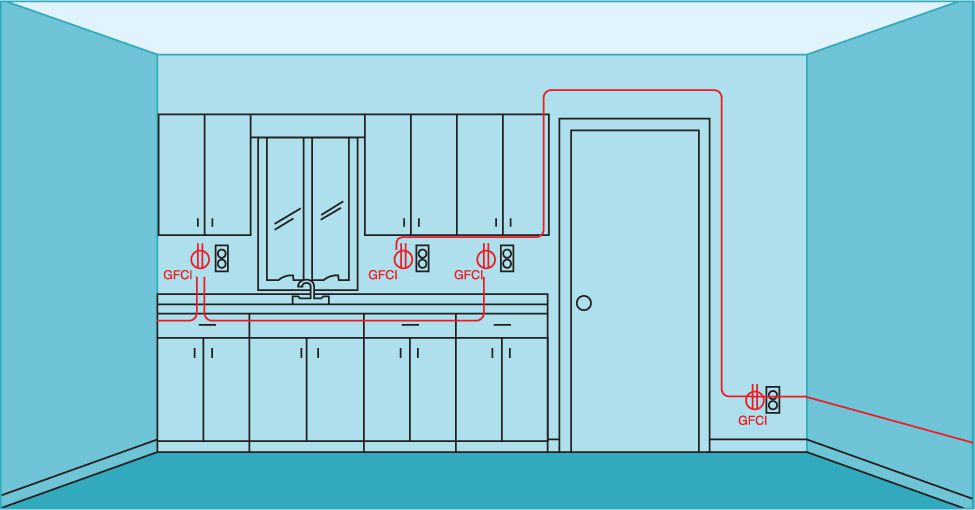
2. GFCI RECEPTACLES (SINGLE-LOCATION PROTECTION)
Use this layout when receptacles are within 6 ft. of a water source, such as those in kitchens and bathrooms. To prevent nuisance tripping caused by normal power surges, GFCIs should be connected only at the line screw terminal so they protect a single location, not the fixtures on the load side of the circuit. Requires two-wire cables. Where a GFCI must protect other fixtures, use circuit map 3. Remember that bathroom receptacles should usually be on a dedicated 20-amp circuit and that all bathroom receptacles must be GFCI-protected.
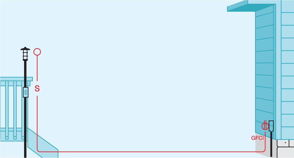
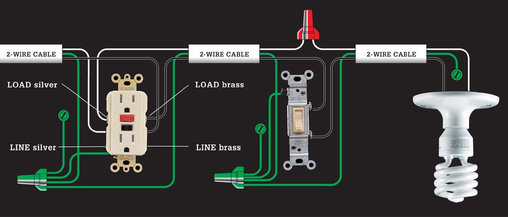
3. GFCI RECEPTACLE, SWITCH & LIGHT FIXTURE (WIRED FOR MULTIPLE-LOCATION PROTECTION)
In some locations, such as an outdoor circuit, it is a good idea to connect a GFCI receptacle so it also provides shock protection to the wires and fixtures that continue to the end of the circuit. Wires from the power source are connected to the line screw terminals; outgoing wires are connected to load screws. Requires two-wire cables.
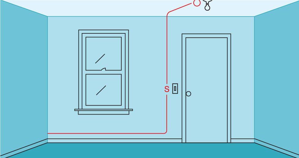
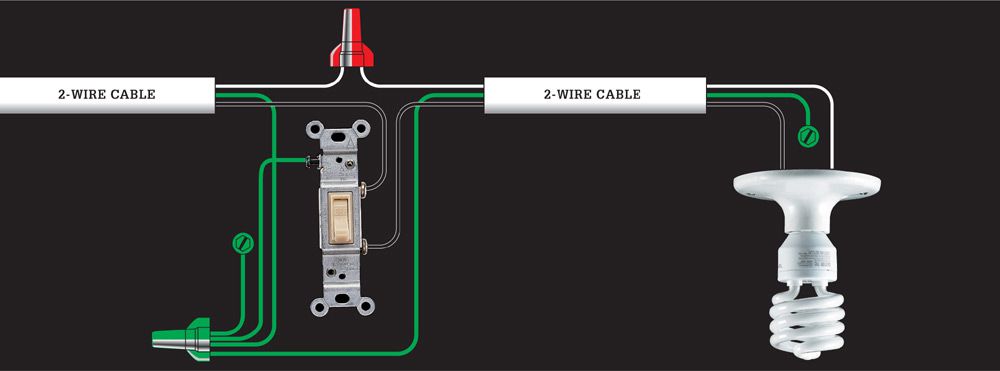
4. SINGLE-POLE SWITCH & LIGHT FIXTURE (LIGHT FIXTURE AT END OF CABLE RUN)
Use this layout for light fixtures in basic lighting/receptacle circuits throughout the home. It is often used as an extension to a series of receptacles (circuit map 1). Requires two-wire cables.
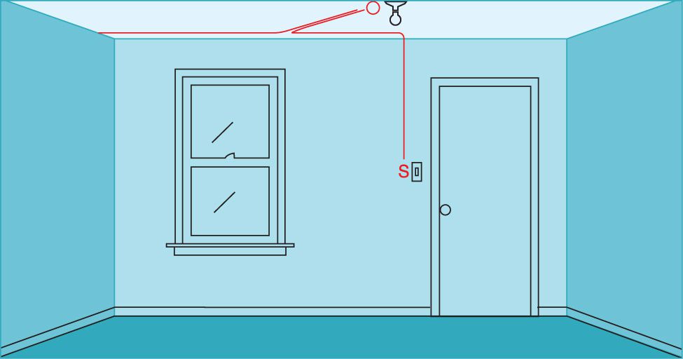
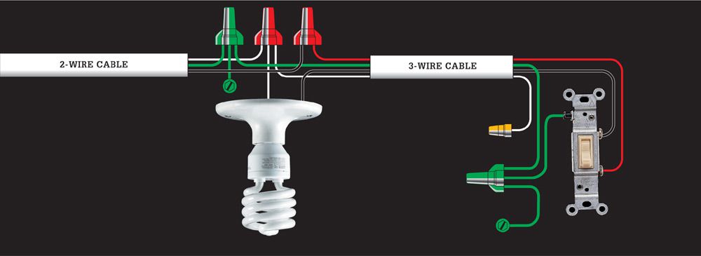
5. SINGLE-POLE SWITCH & LIGHT FIXTURE (SWITCH AT END OF CABLE RUN)
Use this layout, sometimes called a switch loop, where it is more practical to locate a switch at the end of the cable run. In the last length 3-wire cable is used to make a hot conductor available in each direction. Requires two-wire and three-wire cables.
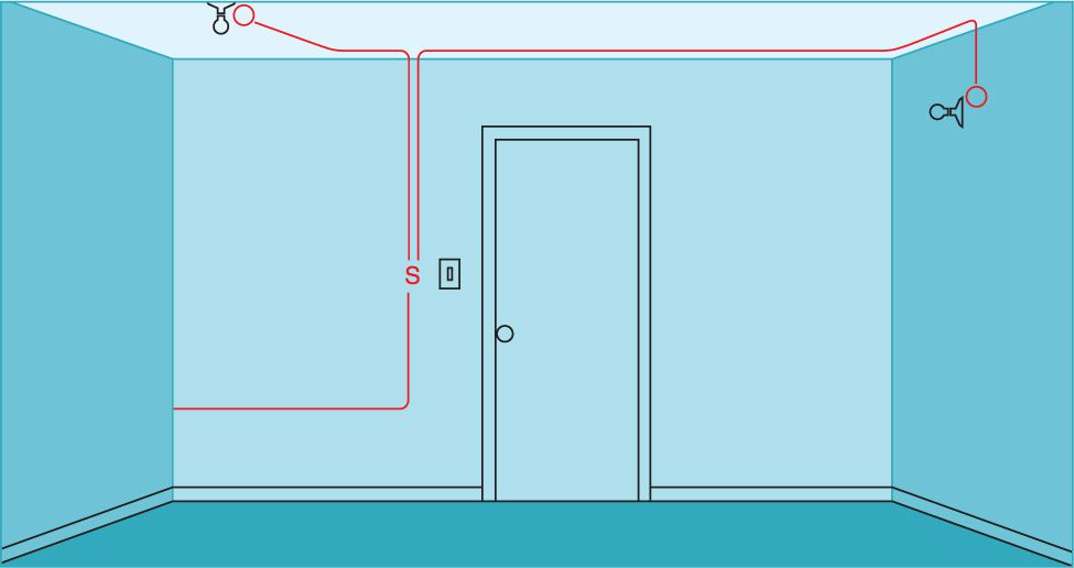
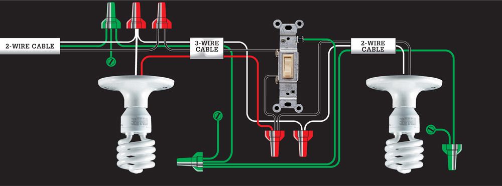
6. SINGLE-POLE SWITCH & TWO LIGHT FIXTURES (SWITCH BETWEEN LIGHT FIXTURES, LIGHT AT START OF CABLE RUN)
Use this layout when you need to control two fixtures from one single-pole switch and the switch is between the two lights in the cable run. Power feeds to one of the lights. Requires two-wire and three-wire cables.
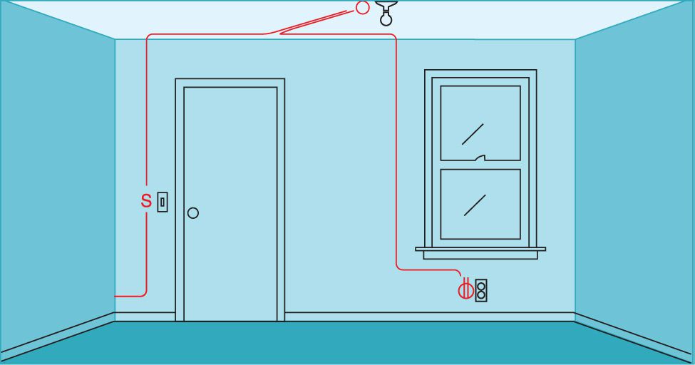
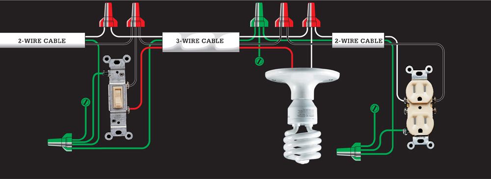
7. SINGLE-POLE SWITCH & LIGHT FIXTURE, DUPLEX RECEPTACLE (SWITCH AT START OF CABLE RUN)
Use this layout to continue a circuit past a switched light fixture to one or more duplex receptacles. To add multiple receptacles to the circuit, see circuit map 1. Requires two-wire and three-wire cables.
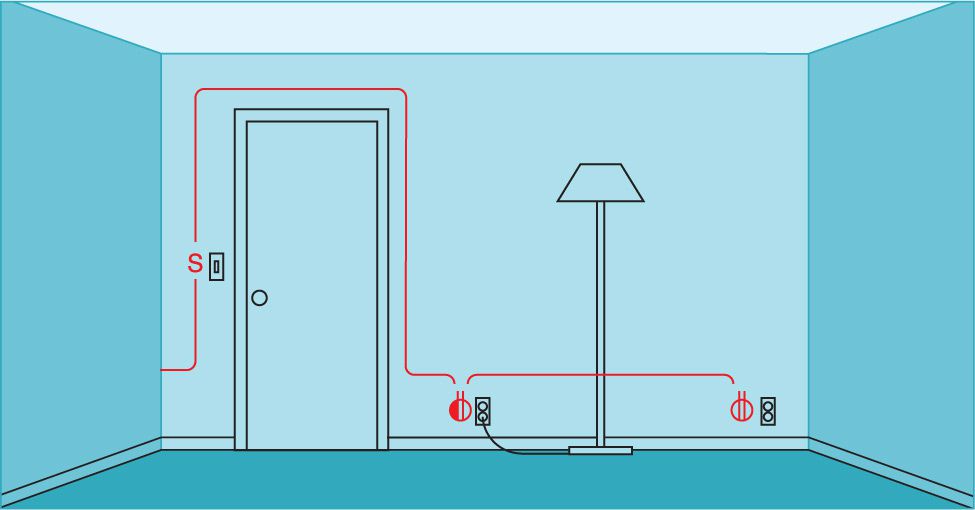
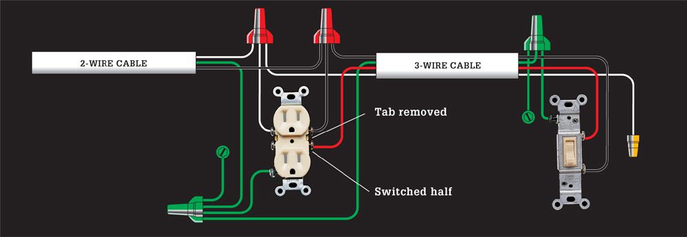
8. SWITCH-CONTROLLED SPLIT RECEPTACLE, DUPLEX RECEPTACLE (SWITCH AT START OF CABLE RUN)
This layout lets you use a wall switch to control a lamp plugged into a wall receptacle. This configuration is required by code for any room that does not have a switch-controlled wall or ceiling fixture. Only the bottom half of the first receptacle is controlled by the wall switch; the top half of the receptacle and all additional receptacles on the circuit are always hot. Requires two-wire and three-wire cables. Some electricians help people identify switched receptacles by installing them upside down.

9. SWITCH-CONTROLLED SPLIT RECEPTACLE (SWITCH AT END OF CABLE RUN)
Use this switch loop layout to control a split receptacle (see circuit map 7) from an end-of-run circuit location. The bottom half of the receptacle is controlled by the wall switch, while the top half is always hot. Requires two-wire and three-wire cable. Some electricians help people identify switched receptacles by installing them upside down.

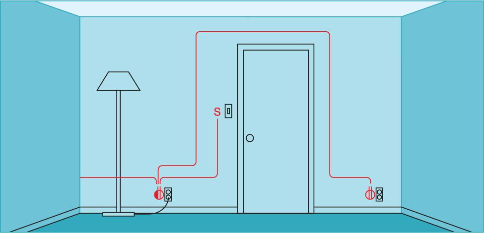
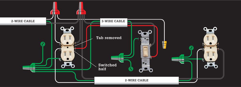
10. SWITCH-CONTROLLED SPLIT RECEPTACLE, DUPLEX RECEPTACLE (SPLIT RECEPTACLE AT START OF RUN)
Use this variation of circuit map 7 where it is more practical to locate a switch-controlled receptacle at the start of a cable run. Only the bottom half of the first receptacle is controlled by the wall switch; the top half of the receptacle, and all other receptacles on the circuit, are always hot. Requires two-wire and three-wire cables. Some electricians help people identify switched receptacles by installing them upside down.
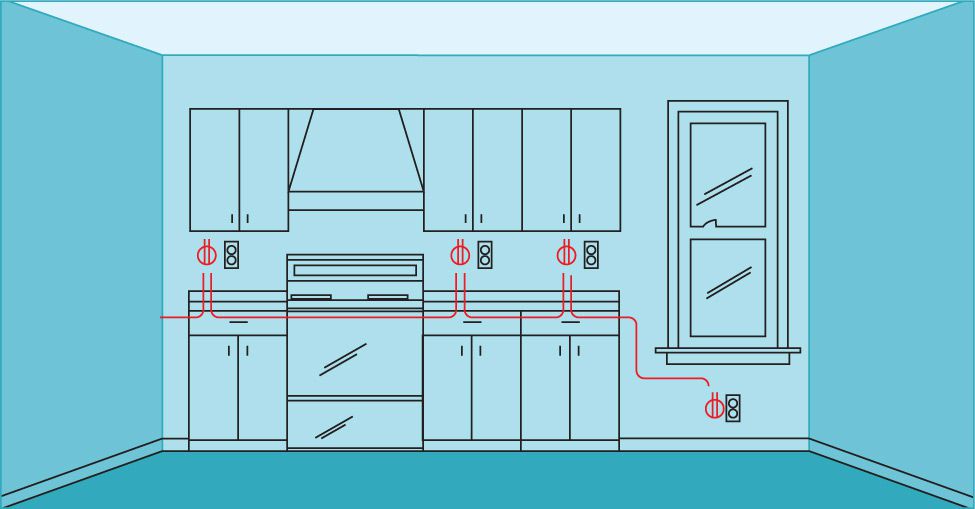
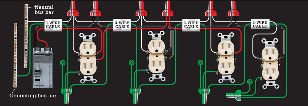
11. DOUBLE RECEPTACLE CIRCUIT WITH SHARED NEUTRAL WIRE (RECEPTACLES ALTERNATE CIRCUITS)
This layout features two 120-volt circuits wired with one three-wire cable connected to a double-pole circuit breaker. The black hot wire powers one circuit; the red wire powers the other. The white wire is a shared neutral that serves both circuits. When wired with 12/2 and 12/3 cable and receptacles rated for 20 amps, this layout can be used for the two small-appliance circuits required in a kitchen. Remember to use a GFCI circuit breaker if you use this circuit for kitchen counter top receptacles.
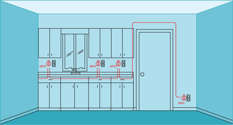
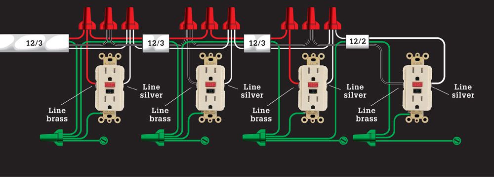
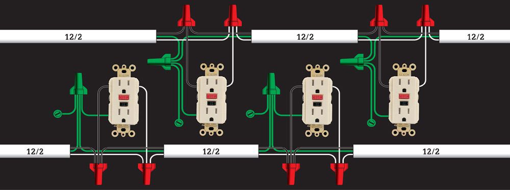
12. DOUBLE RECEPTACLE SMALL-APPLIANCE CIRCUIT WITH GFCIS & SHARED NEUTRAL WIRE
Use this layout variation of circuit map 10 to wire a double receptacle circuit when code requires that some of the receptacles be GFCIs. The GFCIs should be wired for single-location protection (see circuit map 2). Requires three-wire and two-wire cables.
13. DOUBLE RECEPTACLE SMALL APPLIANCE CIRCUIT WITH GFCIS & SEPARATE NEUTRAL WIRES
If the room layout or local codes do not allow for a shared neutral wire, use this layout instead. The GFCIs should be wired for single-location protection (see circuit map 2). Requires two-wire cable.
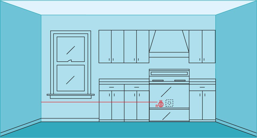
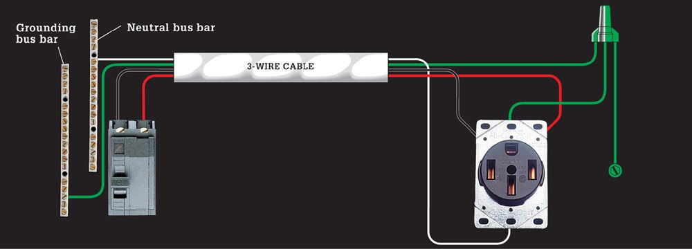
14. 120/240-VOLT RANGE RECEPTACLE
This layout is for a 40- or 50-amp, 120/240-volt dedicated appliance circuit wired with 8/3 or 6/3 cable, as required by code for a large kitchen range. The black and red circuit wires, connected to a double-pole circuit breaker in the circuit breaker panel, each bring 120 volts of power to the setscrew terminals on the receptacle. The white circuit wire attached to the neutral bus bar in the circuit breaker panel is connected to the neutral setscrew terminal on the receptacle.
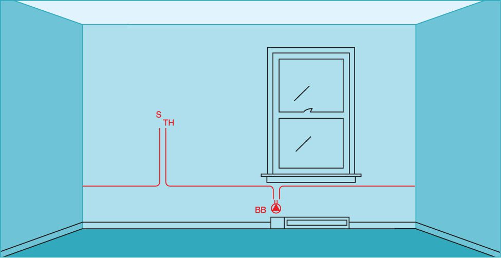
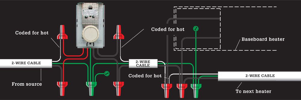
15. 240-VOLT BASEBOARD HEATERS, THERMOSTAT
This layout is typical for a series of 240-volt baseboard heaters controlled by a wall thermostat. Except for the last heater in the circuit, all heaters are wired as shown below. The last heater is connected to only one cable. The sizes of the circuit and cables are determined by finding the total wattage of all heaters. Requires two-wire cable.
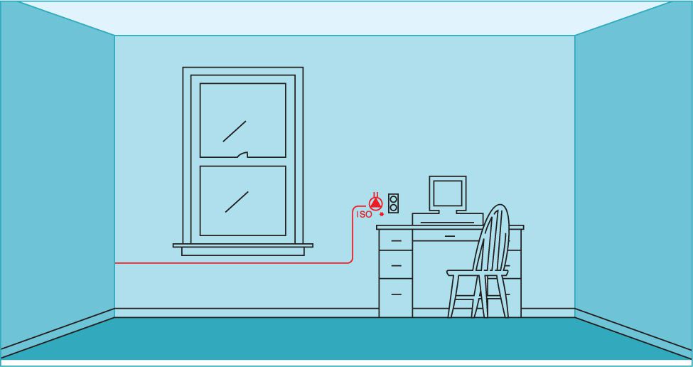
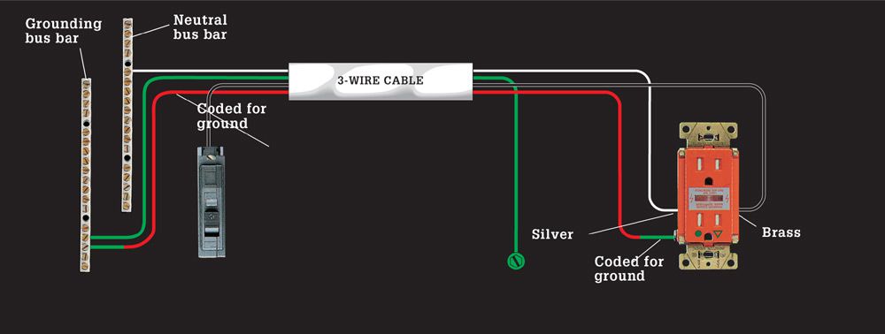
16. DEDICATED 120-VOLT COMPUTER CIRCUIT, ISOLATED-GROUND RECEPTACLE
This 15-amp isolated-ground circuit provides extra protection against surges and interference that can harm electronics. It uses 14/3 cable with the red wire serving as an extra grounding conductor. The red wire is tagged with green tape for identification. It is connected to the grounding screw on an isolated-ground receptacle and runs back to the grounding bus bar in the circuit breaker panel without touching any other house wiring.
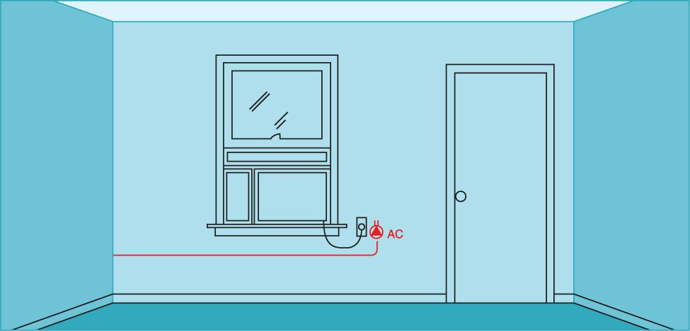
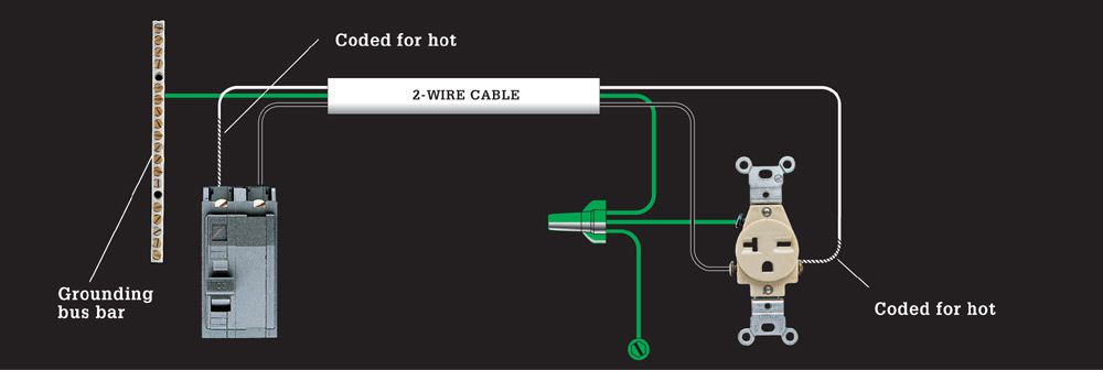
17. 240-VOLT APPLIANCE RECEPTACLE
This layout represents a 20-amp, 240-volt dedicated appliance circuit wired with 12/2 cable, as required by code for a large window air conditioner. Receptacles are available in both singleplex (shown) and duplex styles. The black and the white circuit wires connected to a double-pole breaker each bring 120 volts of power to the receptacle (combined, they bring 240 volts). The white wire is tagged with black tape to indicate it is hot.
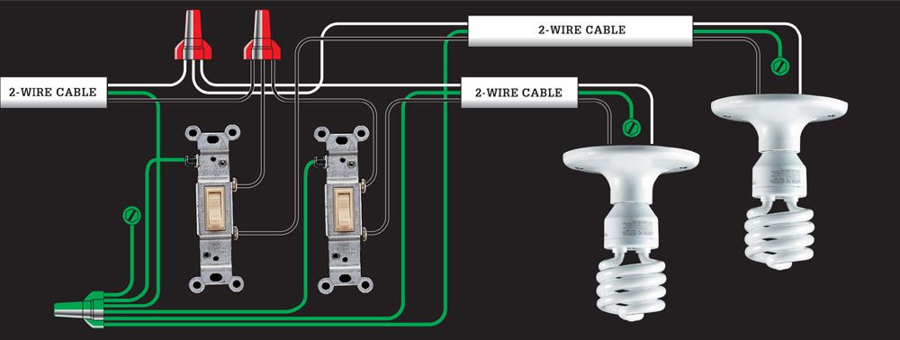
18. GANGED SINGLE-POLE SWITCHES CONTROLLING SEPARATE LIGHT FIXTURES
This layout lets you place two switches controlled by the same 120-volt circuit in one double-gang electrical box. A single-feed cable provides power to both switches. A similar layout with two feed cables can be used to place switches from different circuits in the same box. Requires two-wire cable.
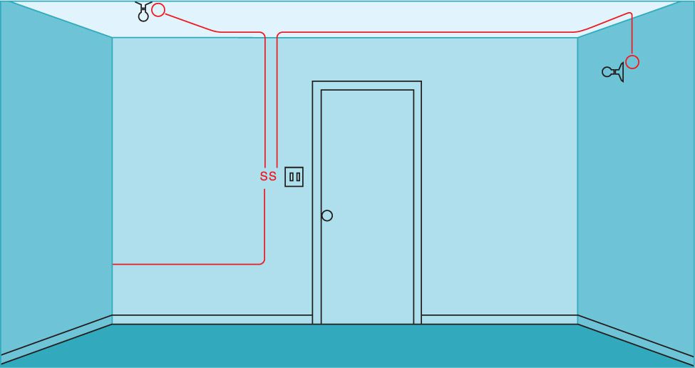
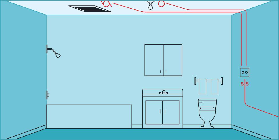
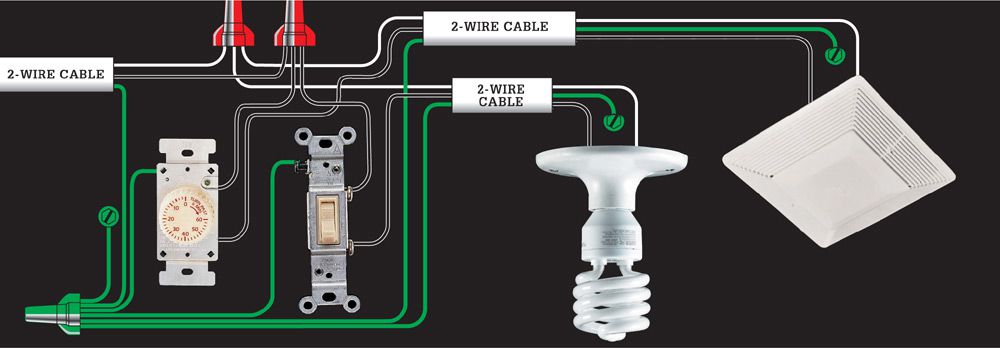
19. GANGED SWITCHES CONTROLLING A LIGHT FIXTURE AND A VENT FAN
This layout lets you place two switches controlled by the same 120-volt circuit in one double-gang electrical box. A single-feed cable provides power to both switches. A standard switch controls the light fixture, and a time-delay switch controls the vent fan.
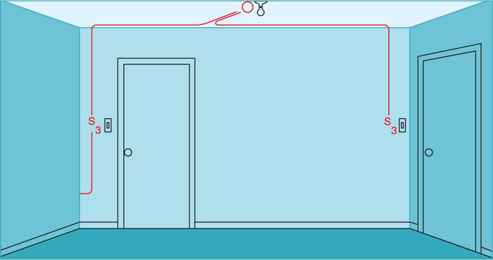
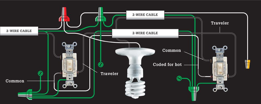
20. THREE-WAY SWITCHES & LIGHT FIXTURE (FIXTURE BETWEEN SWITCHES)
This layout for three-way switches lets you control a light fixture from two locations. Each switch has one common screw terminal and two traveler screws. Circuit wires attached to the traveler screws run between the two switches, and hot wires attached to the common screws bring current from the power source and carry it to the light fixture. Requires parallel runs of 2-wire cable.
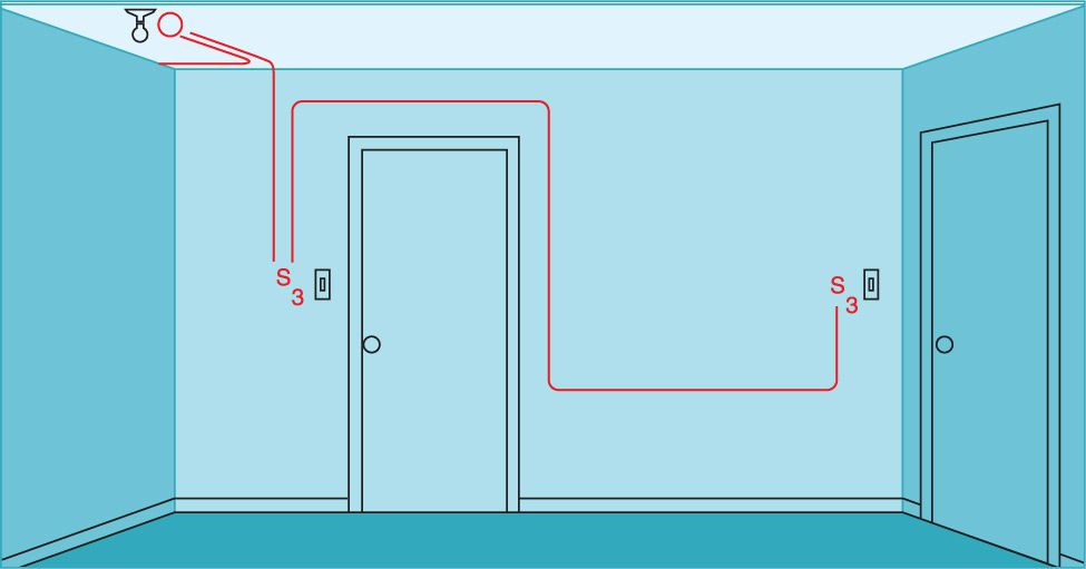
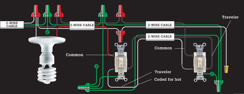
21. THREE-WAY SWITCHES & LIGHT FIXTURE (FIXTURE AT START OF CABLE RUN)
Use this layout variation of circuit map 19 where it is more convenient to locate the fixture ahead of the three-way switches in the cable run. Requires two-wire and three-wire cables.
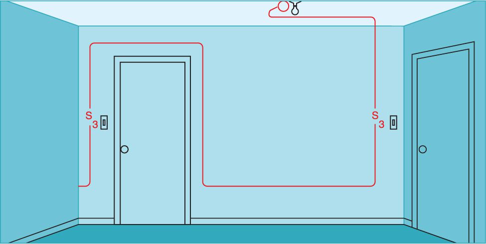
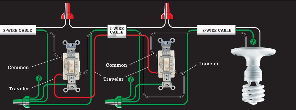
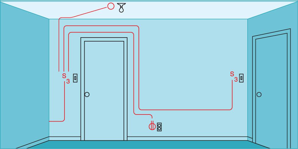
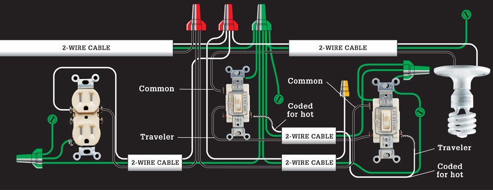
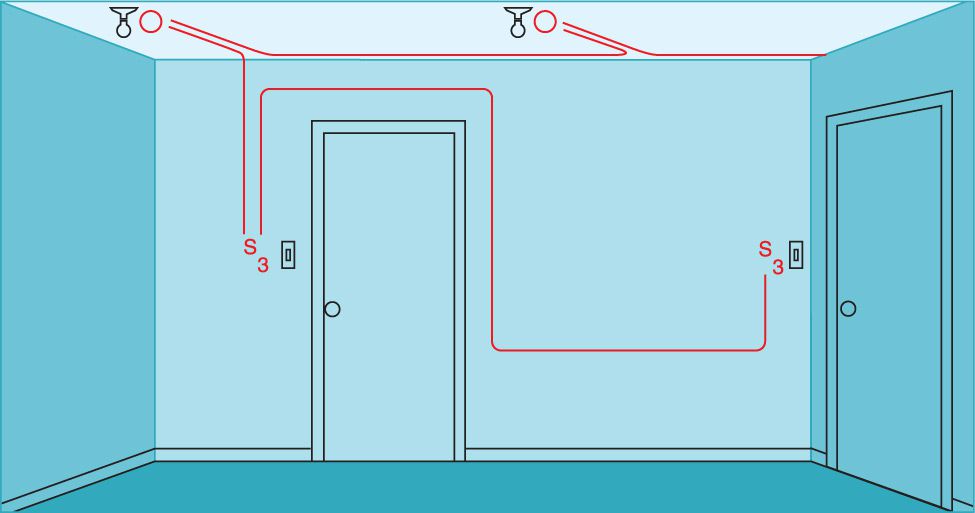
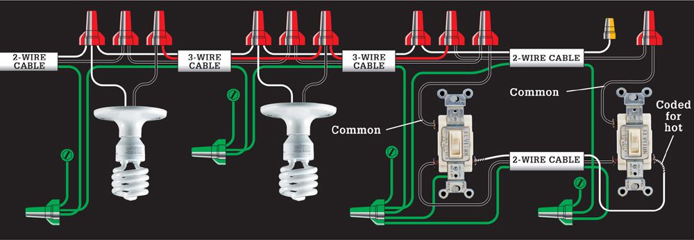
22. THREE-WAY SWITCHES & LIGHT FIXTURE (FIXTURE AT END OF CABLE RUN)
This variation of the three-way switch layout (circuit map 20) is used where it is more practical to locate the fixture at the end of the cable run. Requires two-wire and three-wire cables.
23. THREE-WAY SWITCHES & LIGHT FIXTURE WITH DUPLEX RECEPTACLE
Use this layout to add a receptacle to a three-way switch configuration (circuit map 21). Requires two-wire and parallel runs of two-wire cables.
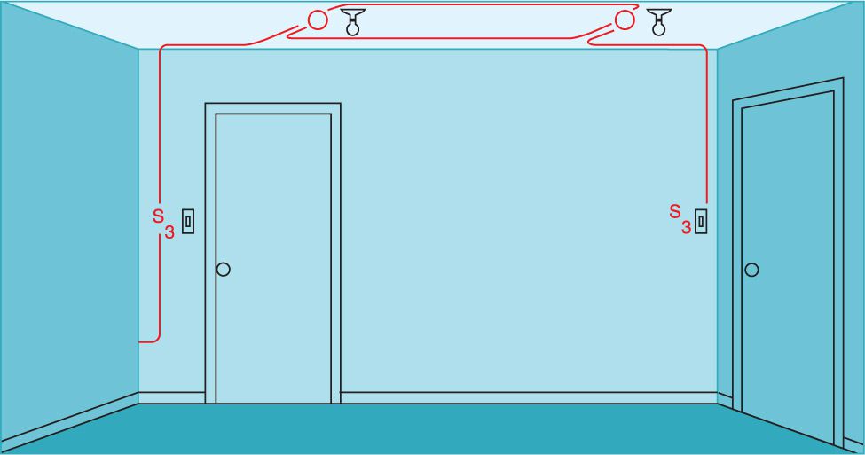
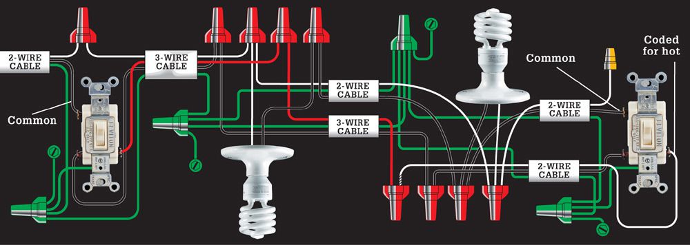
24. THREE-WAY SWITCHES & MULTIPLE LIGHT FIXTURES (FIXTURES BETWEEN SWITCHES)
This is a variation of circuit map 20. Use it to place multiple light fixtures between two three-way switches where power comes in at one of the switches. Requires two- and three-wire cable.
25. THREE-WAY SWITCHES & MULTIPLE LIGHT FIXTURES (FIXTURES AT BEGINNING OF RUN)
This is a variation of circuit map 21. Use it to place multiple light fixtures at the beginning of a run controlled by two three-way switches. Power comes in at the first fixture. Requires two- and three-wire cable.
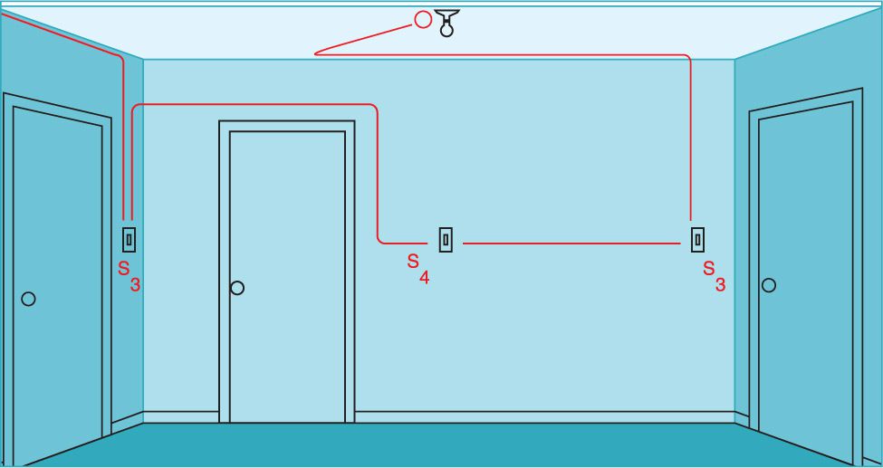
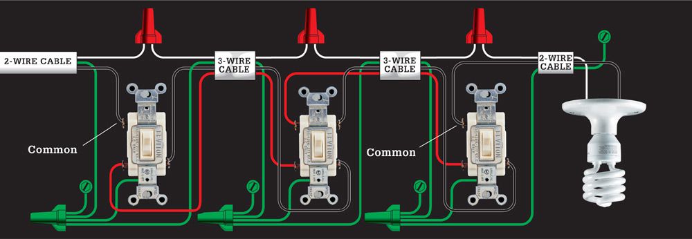
26. FOUR-WAY SWITCH & LIGHT FIXTURE (FIXTURE AT START OF CABLE RUN)
This layout lets you control a light fixture from three locations. The end switches are three-way, and the middle is four-way. A pair of three-wire cables enter the box of the four-way switch. The white and red wires from one cable attach to the top pair of screw terminals (line 1), and the white and red wires from the other cable attach to the bottom screw terminals (line 2). Requires two three-way switches and one four-way switch and two-wire and three-wire cables.
27. FOUR-WAY SWITCH & LIGHT FIXTURE (FIXTURE AT END OF CABLE RUN)
Use this layout variation of circuit map 26 where it is more practical to locate the fixture at the end of the cable run. Requires two three-way switches and one four-way switch and two-wire and three-wire cables.
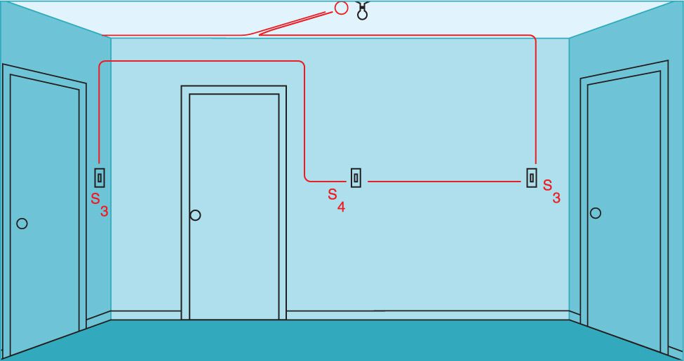
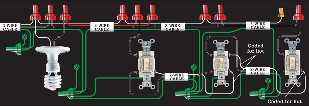
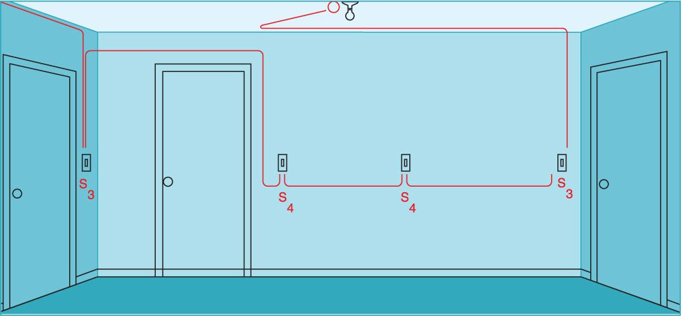
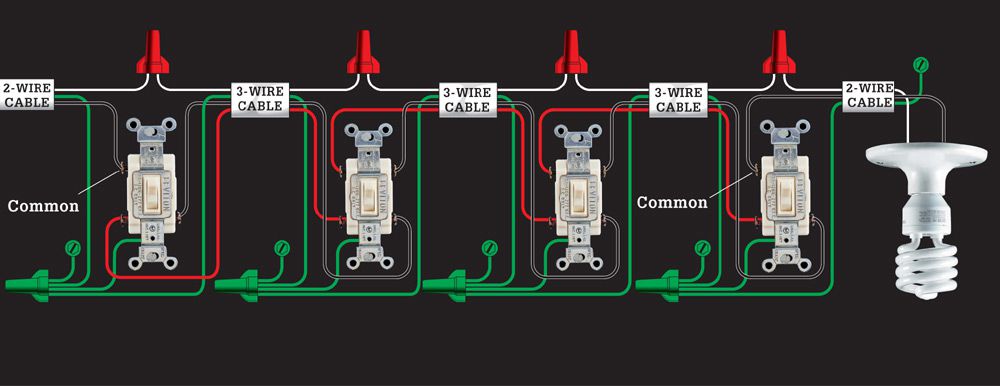
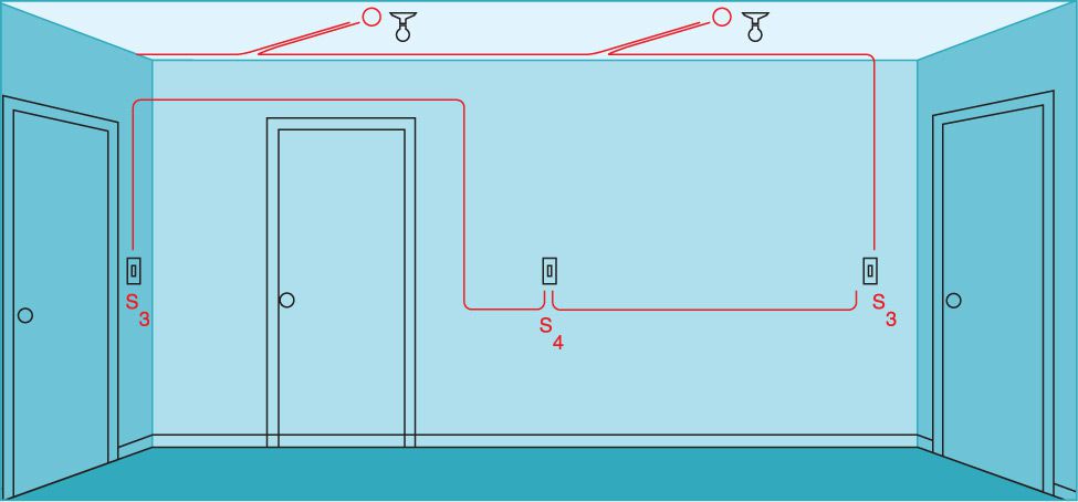
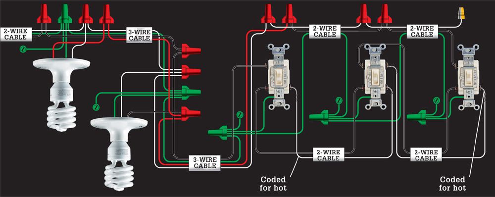
28. MULTIPLE FOUR-WAY SWITCHES CONTROLLING A LIGHT FIXTURE
This alternate variation of the four-way switch layout (circuit map 27) is used where three or more switches will control a single fixture. The outer switches are three-way, and the middle are four-way. Requires two three-way switches and two four-way switches and two-wire and three-wire cables.
29. FOUR-WAY SWITCHES & MULTIPLE LIGHT FIXTURES
This variation of the four-way switch layout (circuit map 26) is used where two or more fixtures will be controlled from multiple locations in a room. Outer switches are three-way, and the middle switch is a four-way. Requires two three-way switches and one four-way switch and two-wire and three-wire cables.
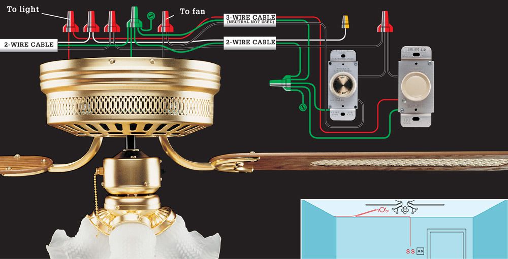
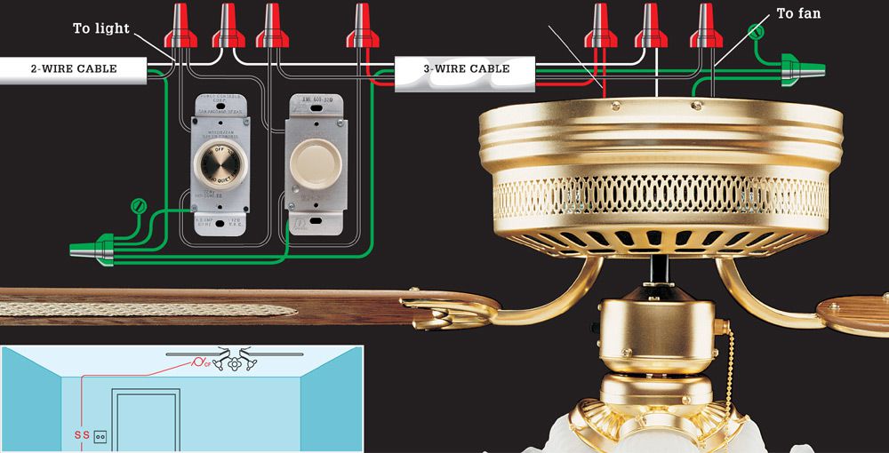
30. CEILING FAN/LIGHT FIXTURE CONTROLLED BY GANGED SWITCHES (FAN AT END OF CABLE RUN)
This layout is for a combination ceiling fan/light fixture controlled by a speed-control switch and dimmer in a double-gang switch box. Requires two-wire and three-wire cables.
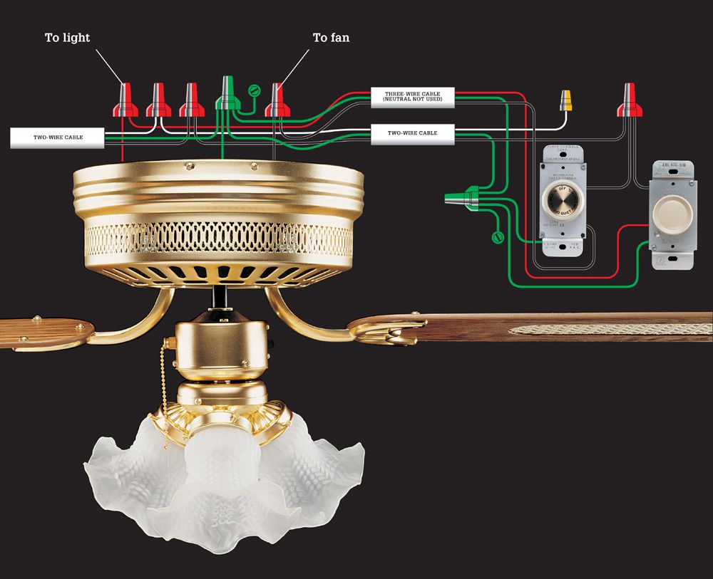
31. CEILING FAN/LIGHT FIXTURE CONTROLLED BY GANGED SWITCHES (SWITCHES AT END OF CABLE RUN)
Use this switch loop layout variation when it is more practical to install the ganged speed control and dimmer switches for the ceiling fan at the end of the cable run. Requires two-wire and parallel runs of two-wire cables.