The Complete Guide to Wiring, Updated 6th Edition: Current with 2014-2017 Electrical Codes - Black & Decker, Cool Springs Press (2014)
Chapter 5. Receptacles

Whether you call them outlets, plug-ins, or receptacles, these important devices represent the point where the rubber meets the road in your home wiring system. From the basic 15-amp, 120-volt duplex receptacle to the burly 50-amp, 240-volt appliance receptacle, the many receptacles in your home do pretty much the same thing: transmit power to a load.
Learning the differences between receptacles does not take long. You need to know the amperage, voltage, and the number of devices on the circuit to select the correct receptacle. For circuits with one receptacle, match the circuit and receptacle amperage and voltage. A duplex receptacle (with a space for two plugs) counts as two receptacles. Use 15-amp receptacles on 15-amp circuits with multiple receptacles. Use either 15- or 20-amp receptacles on 20-amp circuits with multiple receptacles. Twenty-amp receptacles have the horizontal slot that forms a T with the large slot. Receptacles for 240-volt service have unique slot configurations so you can’t accidentally plug in an appliance that’s not rated for the amperage in the circuit. Though some receptacles can be wired using the push-in wire holes, this method is not recommended. If you use this method, use only 15-amp receptacles with #14 wire and 20-amp receptacles with #12 wire. Some receptacles provide built-in, ground-fault circuit protection, tripping the receptacle if there is a ground fault or power surge. These are easy to identify by reset and test buttons.
One last bit of information about receptacles: like switches, they vary quite a bit in quality. Paying the extra couple of dollars for a well made, durable device is worth the money.
In this chapter:
![]() Types of Receptacles
Types of Receptacles
![]() Receptacle Wiring
Receptacle Wiring
![]() GFCI Receptacles
GFCI Receptacles
![]() Testing Receptacles
Testing Receptacles
![]() Types Of Receptacles
Types Of Receptacles
Several different types of receptacles are found in the typical home. Each has a unique arrangement of slots that accepts only a certain kind of plug, and each is designed for a specific job.
Household receptacles provide two types of voltage: normal and high. Although voltage ratings have changed slightly over the years, normal receptacles should be rated for 110, 115, 120, or 125 volts. For purposes of replacement, these ratings are considered identical. High-voltage receptacles are rated at 220, 240, or 250 volts. These ratings are considered identical.
When replacing a receptacle, check the amperage rating of the circuit at the main service panel, and buy a receptacle with the correct amperage rating.
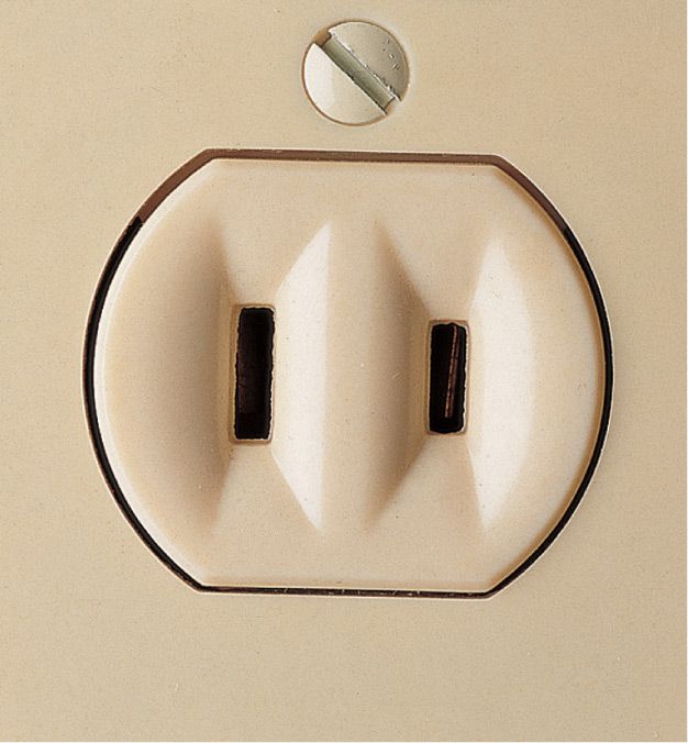
15 amps, 120 volts. Polarized two-slot receptacles are common in homes built before 1960. Slots are different sizes to accept polarized plugs.
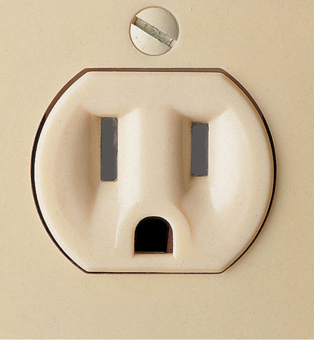
15 amps, 120 volts. Three-slot grounded receptacles have two different-sized slots and a U-shaped hole for grounding which is required in all new wiring installations.
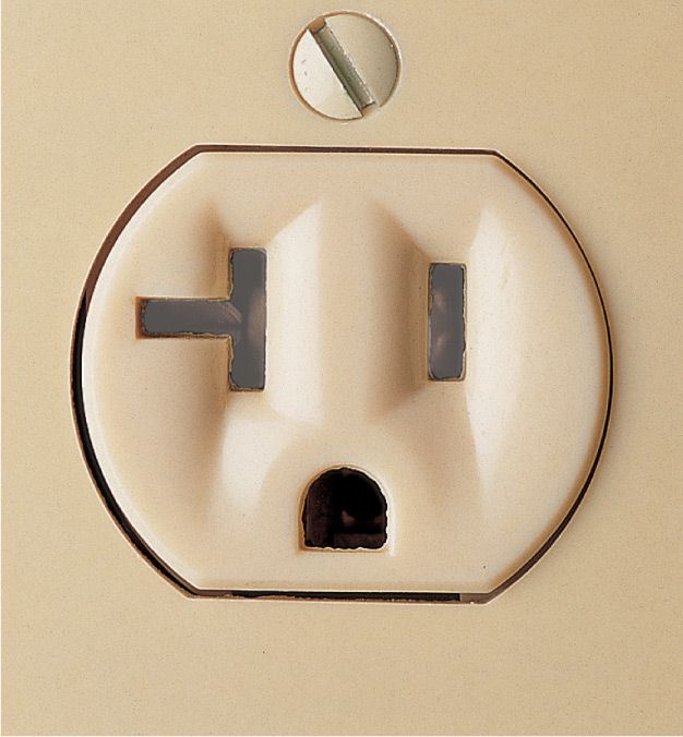
20 amps, 120 volts. This three-slot grounded receptacle features a special T-shaped slot. It is installed for use with large appliances or portable tools that require 20 amps of current.
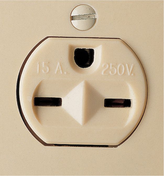
15 amps, 240 volts. This receptacle is used primarily for window air conditioners. It is available as a single unit or as half of a duplex receptacle, with the other half wired for 120 volts.
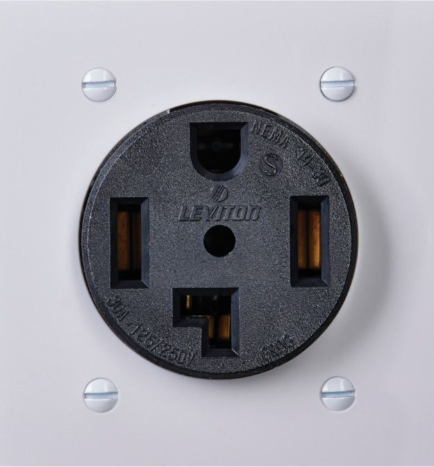
30 amps, 120/240 volts. This grounded receptacle is used for clothes dryers. It provides high-voltage current for heating coils and 120-volts to run lights and timers.
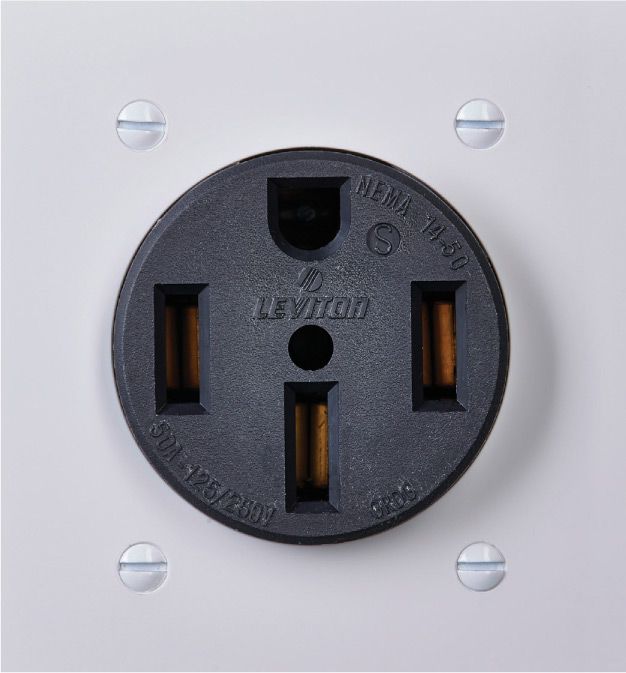
50 amps, 120/240 volts. This new, grounded receptacle is used for ranges. The high voltage powers heating coils, and the 120-volts run clocks and lights.
![]() Older Receptacles
Older Receptacles
Older receptacles may look different from more modern types, but most will stay in good working order. Follow these simple guidelines for evaluating or replacing older receptacles:
✵ Never replace a receptacle with one of a different voltage or higher amperage rating.
✵ Do not replace a two-slot receptacle with a three-slot receptacle. Replace the two-slot receptacle with a polarized two-slot receptacle or with a GFCI receptacle.
✵ If in doubt, contact an electrician.
✵ Never alter the prongs of a plug to fit an older receptacle. Altering the prongs may remove the grounding or polarizing features of the plug.
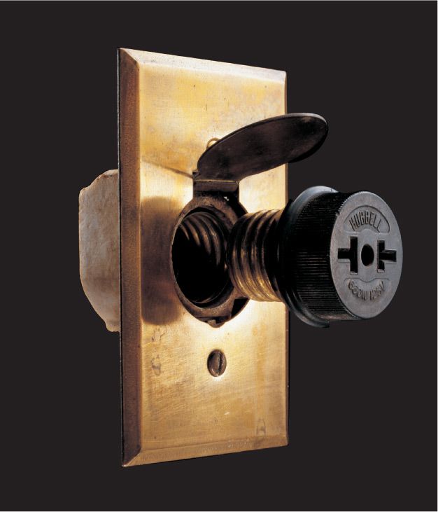
The earliest receptacles were modifications of the screw-in light bulb. This receptacle was used in the early 1900s.
Unpolarized receptacles have same-length slots. Modern plugs may not fit these receptacles. Never modify the prongs of a polarized plug to fit the slots of an unpolarized receptacle.
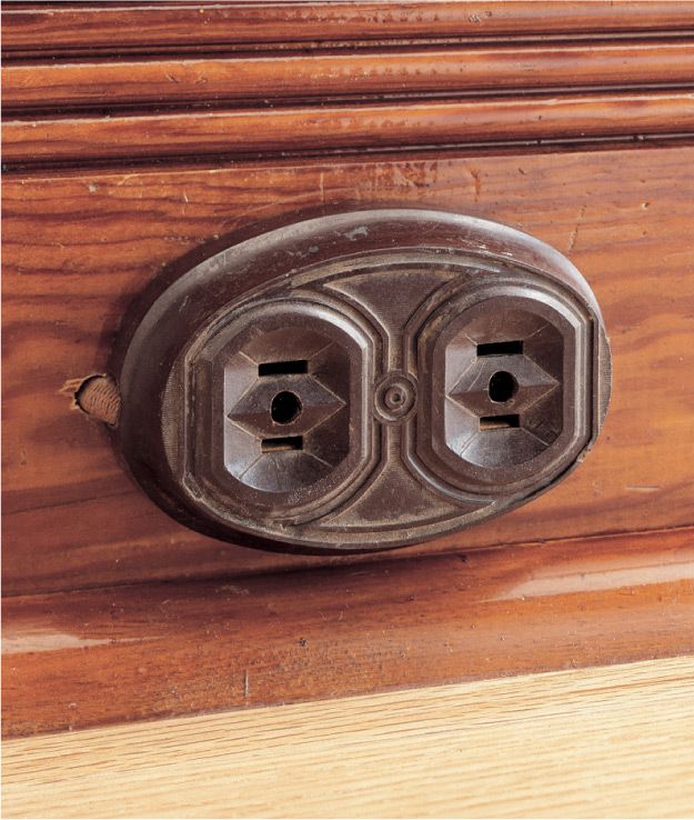
Surface-mounted receptacles were popular in the 1940s and 1950s for their ease of installation. Wiring ran behind hollowed-out base moldings. These receptacles are usually ungrounded.
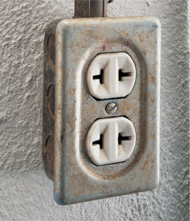
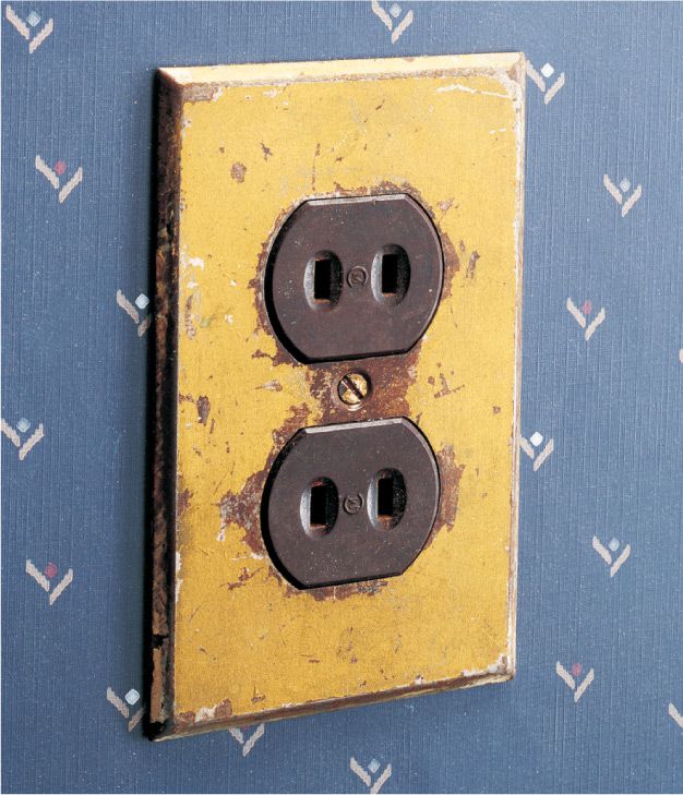
Ceramic duplex receptacles were manufactured in the 1930s. They are polarized but ungrounded, and they are wired for 120 volts.
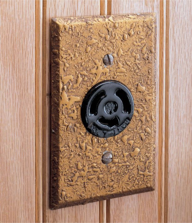
Twist-lock receptacles are designed to be used with plugs that are inserted and rotated. A small tab on the end of one of the prongs prevents the plug from being pulled from the receptacle.
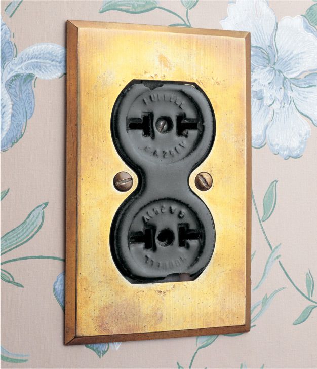
This ceramic duplex receptacle has a unique hourglass shape. It is rated for 250 volts but only 5 amps and would not be allowed by today’s electrical codes.
![]() High-Voltage Receptacles
High-Voltage Receptacles
High-voltage receptacles provide current to large appliances such as clothes dryers, ranges, and air conditioners. The slot configuration of a high-voltage receptacle (page 104) will not accept a plug rated for 120 volts.
A high-voltage receptacle can be wired in one of two ways. In one type of high-voltage receptacle, voltage is brought to the receptacle with two hot wires, each carrying a maximum of 120 volts. No white neutral wire is necessary, but a grounding wire should be attached to the receptacle and to the metal receptacle box. Conduit may also act as a grounding conductor from the metal receptacle box back to the panel in old circuits without a grounding wire. This method is not allowed today.
A clothes dryer or range also may require 120 volts to run lights, timers, and clocks. If so, a white neutral wire will be attached to the receptacle. The appliance itself will split the incoming electricity into a 120-volt circuit and a 240-volt circuit.
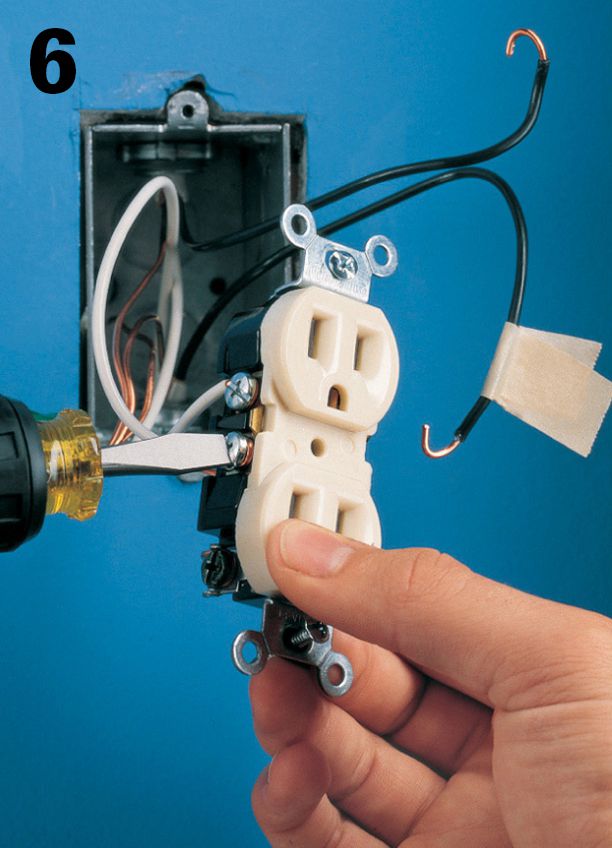
It is important to identify and tag all wires on the existing receptacle so that the new receptacle will be properly wired.
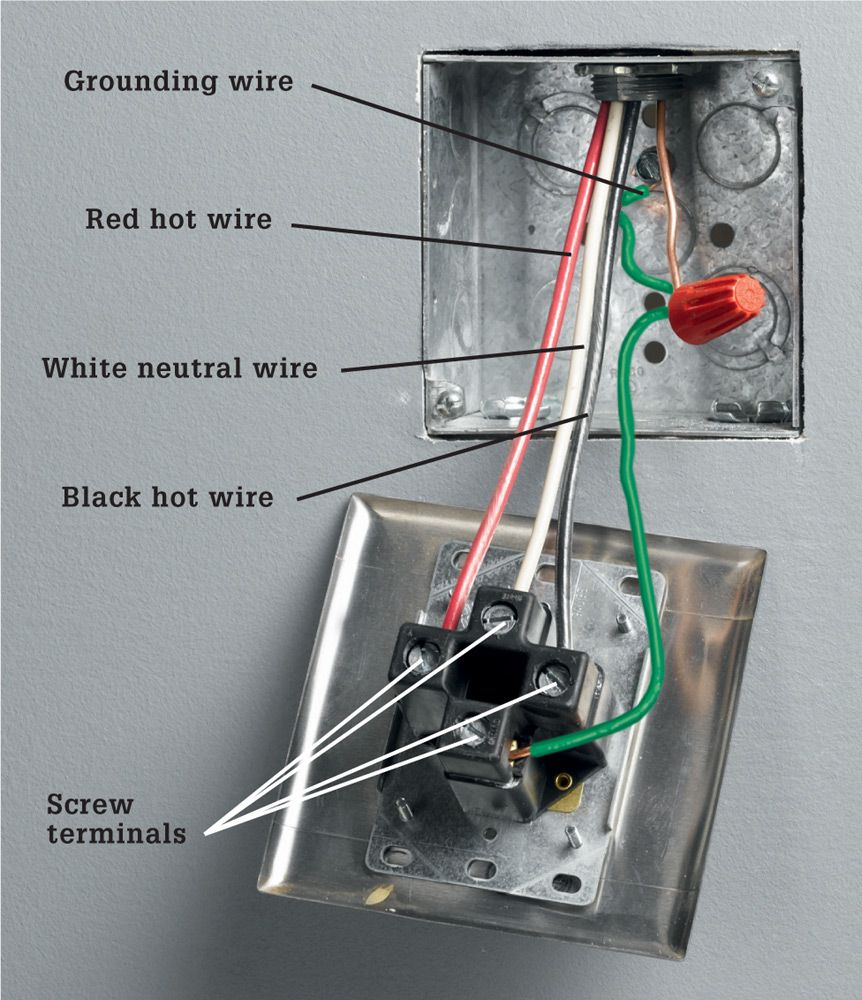
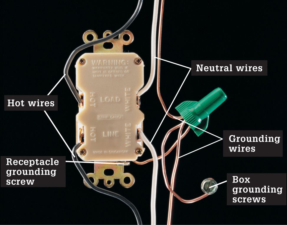
A receptacle rated for 120/240 volts has two incoming hot wires, each carrying 120 volts, a white neutral wire, and a copper grounding wire. Connections are made with setscrew terminals at the back of the receptacle.

One type of receptacle rated for 240 volts has two incoming hot wires and no neutral wire. A grounding wire is pigtailed to the receptacle and to the metal receptacle box.
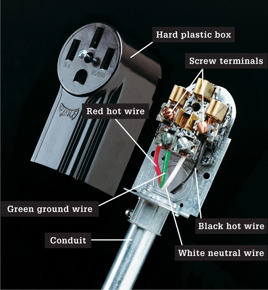
This surface-mounted receptacle rated for 240 volts has a hard plastic box that can be installed on concrete or block walls. Surface-mounted receptacles are often found in basements and utility rooms.
![]() Childproofing
Childproofing
Childproof your receptacles or adapt them for special uses by adding receptacle accessories. Before installing an accessory, be sure to read the manufacturer’s instructions.
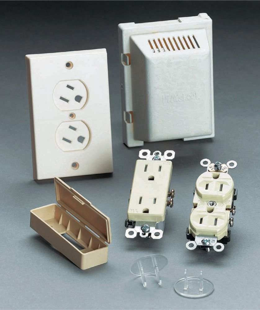
Homeowners with small children should add inexpensive caps or covers to guard against accidental electric shocks.
Plastic caps do not conduct electricity and are virtually impossible for small children to remove. A receptacle cover attaches directly to the receptacle and fits over plugs, preventing the cords from being removed. Tamper-resistant receptacles are now required in all new residential installations.
Standard receptacles present a real shock hazard to small children. Fortunately there are many products that make receptacles safer without making them less convenient.
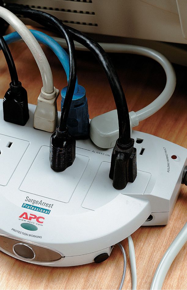
Protect electronic equipment, such as a home computer or stereo, with a surge protector. The surge protector reduces the chance of any damage to sensitive equipment caused by sudden drops or surges in power.
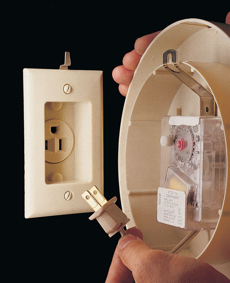
A recessed wall receptacle permits a plug-in clock to be hung flush against a wall surface.
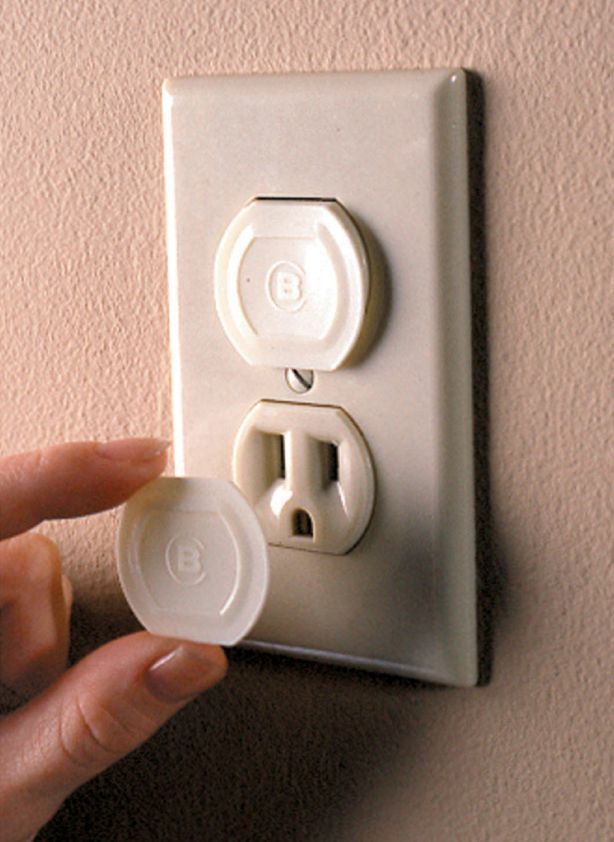
Snap protective caps over sockets to prevent children from having access to the slots.
![]() Duplex Receptacles
Duplex Receptacles
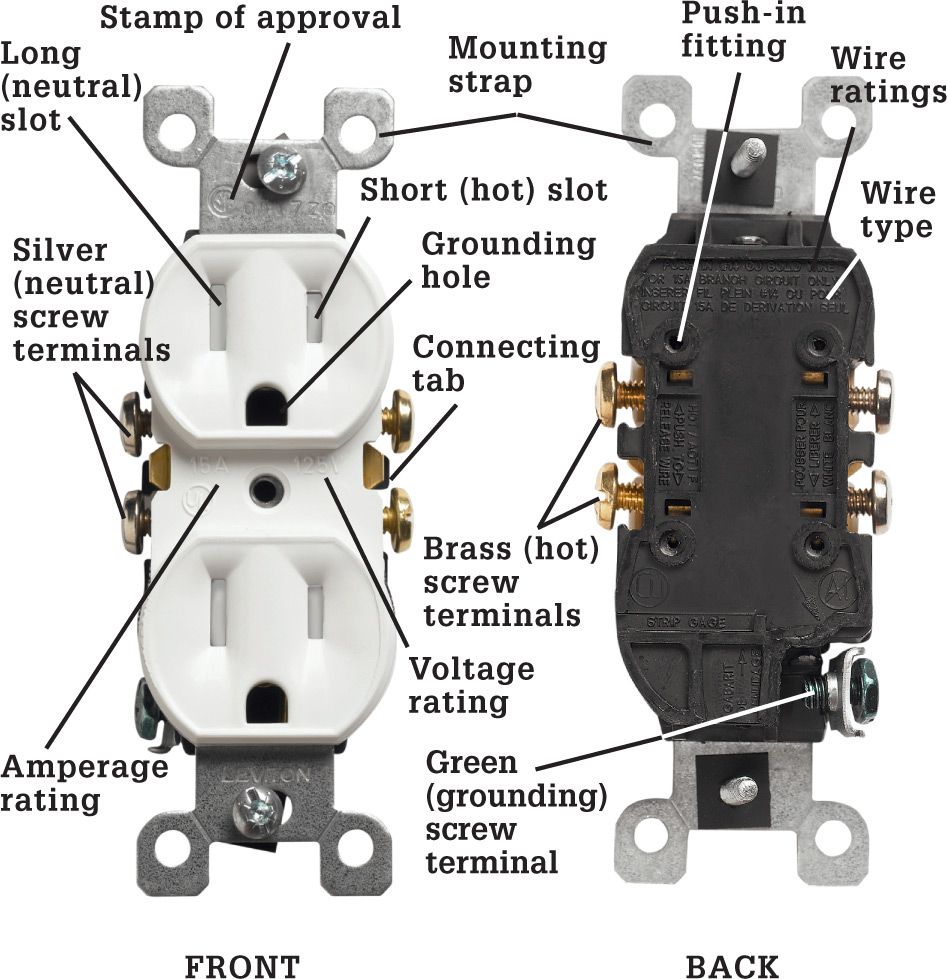
The standard duplex receptacle has two halves for receiving plugs. Each half has a long (neutral) slot, a short (hot) slot, and a U-shaped grounding hole. The slots fit the wide prong, narrow prong, and grounding prong of a three-prong plug. This ensures that the connection between receptacle and plug will be polarized and grounded for safety.
Wires are attached to the receptacle at screw terminals or push-in fittings. A connecting tab between the screw terminals allows a variety of different wiring configurations. Receptacles also include mounting straps for attaching to electrical boxes.
Stamps of approval from testing agencies are found on the front and back of the receptacle. Look for the symbol UL or UND. LAB. INC. LIST to make sure the receptacle meets the strict standards of Underwriters Laboratories.
The receptacle is marked with ratings for maximum volts and amps. The common receptacle is marked 15A, 125V. Receptacles marked CU or COPPER are used with solid copper wire. Those marked CU-CLAD ONLY are used with copper-coated aluminum wire. Only receptacles marked CO/ALR may be used with solid aluminum wiring. Receptacles marked AL/CU no longer may be used with aluminum wire, according to code.
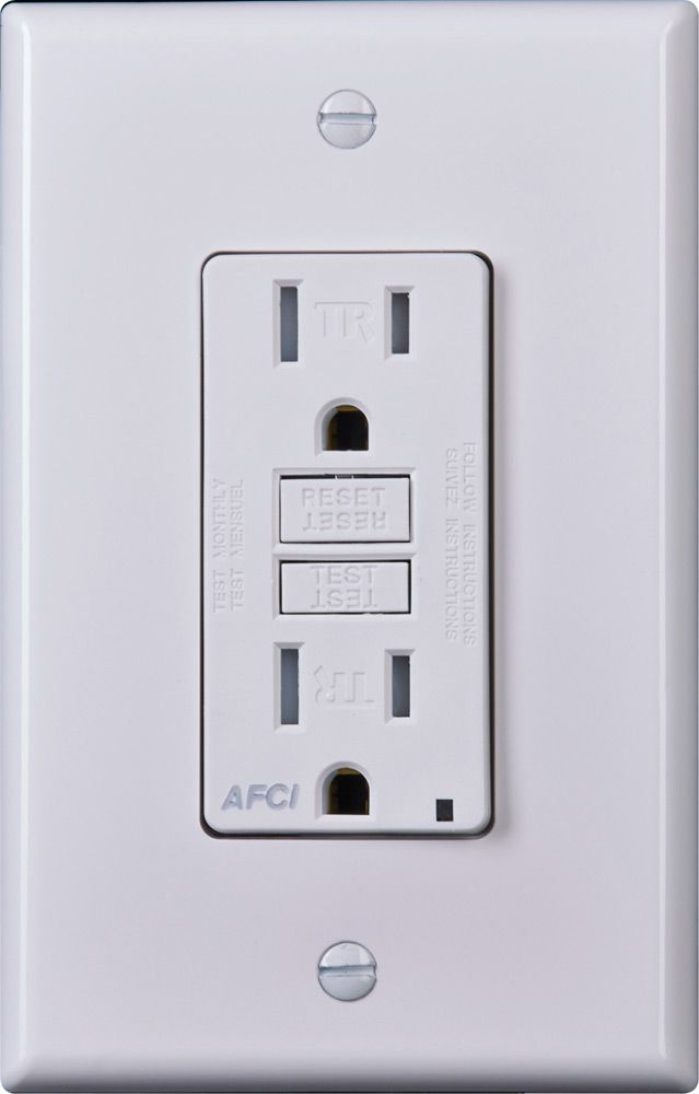
AFCI receptacles have integral protection against arc faults and may be required in some remodeling situations where AFCI protection cannot be provided at the service panel.
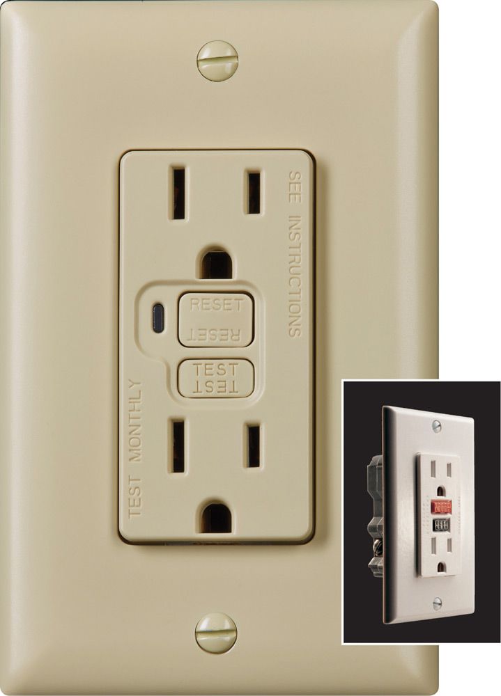
The ground-fault circuit-interrupter, or GFCI, receptacle is a modern safety device. When it detects slight changes in current, it instantly shuts off power. The larger picture shows a modern GFCI with an alert bulb that lights when the device is tripped. The older but more familiar style is seen in the inset photo.
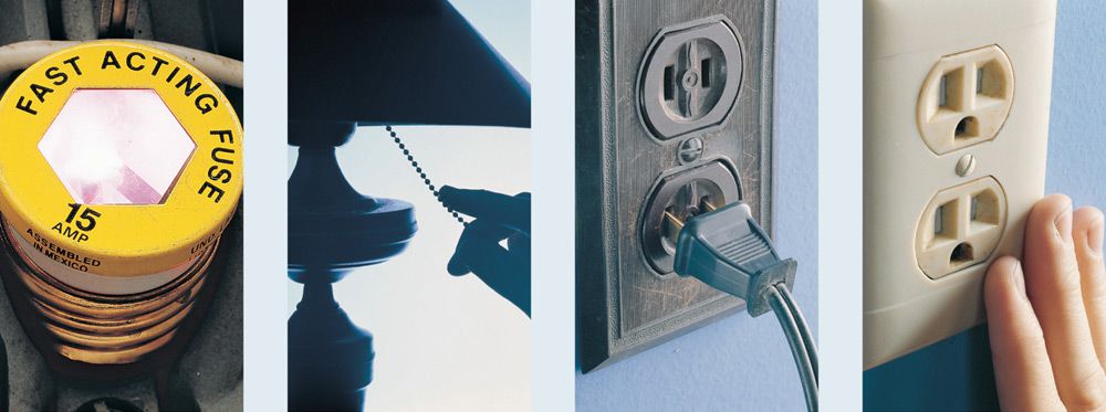
Common Receptacle Problems ![]()
Household receptacles, also called outlets, have no moving parts to wear out and usually last for many years without servicing. Most problems associated with receptacles are actually caused by faulty lamps and appliances or their plugs and cords. However, the constant plugging in and removal of appliance cords can wear out the metal contacts inside a receptacle. Any receptacle that does not hold plugs firmly should be replaced. In addition, older receptacles made of hard plastic may harden and crack with age. They must be replaced when this happens.
A loose wire connection with the receptacle box is another possible problem. A loose connection can spark (called arcing), trip a circuit breaker, or cause heat to build up in the receptacle box, creating a potential fire hazard.
Wires can come loose for a number of reasons. Everyday vibrations caused by walking across floors, or from nearby street traffic, may cause a connection to shake loose. In addition, because wires heat and cool with normal use, the ends of the wires will expand and contract slightly. This movement also may cause the wires to come loose from the screw terminal connections.
Not all receptacles are created equally. When replacing, make sure to buy one with the same amp rating as the old one. Inadvertently installing a 20-amp receptacle in replacement of a 15-amp receptacle is a very common error.
|
PROBLEM |
REPAIR |
|
Circuit breaker trips repeatedly, or fuse burns out immediately after being replaced. |
1. Repair or replace worn or damaged lamp or appliance cord. 2. Move lamps or appliances to other circuits to prevent overloads. 3. Tighten any loose wire connections. 4. Clean dirty or oxidized wire ends. |
|
Lamp or appliance does not work. |
1. Make sure the lamp or appliance is plugged in. 2. Replace burned-out bulbs. 3. Repair or replace a worn or damaged lamp or appliance cord. 4. Tighten any loose wire connections. 5. Clean dirty or oxidized wire ends. 6. Replace any faulty receptacle. |
|
Receptacle does not hold plugs firmly. |
1. Repair or replace worn or damaged plugs. 2. Replace the faulty receptacle. |
|
Receptacle is warm to the touch, buzzes, or sparks when plugs are inserted or removed. |
1. Move lamps or appliances to other circuits to prevent overloads. 2. Tighten any loose wire connections. 3. Clean dirty or oxidized wire ends. 4. Replace the faulty receptacle. |
![]() Receptacle Wiring
Receptacle Wiring
A120-volt duplex receptacle can be wired to the electrical system in several ways. The most common are shown on these pages.
Wiring configurations may vary slightly from these photographs, depending on the kind of receptacles used, the type of cable, or the technique of the electrician who installed the wiring. To make dependable repairs or replacements, use masking tape and label each wire according to its location on the terminals of the existing receptacle.
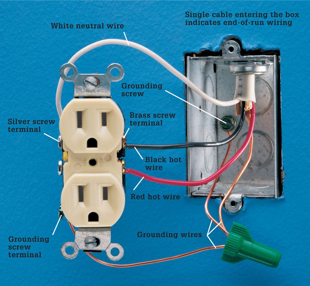
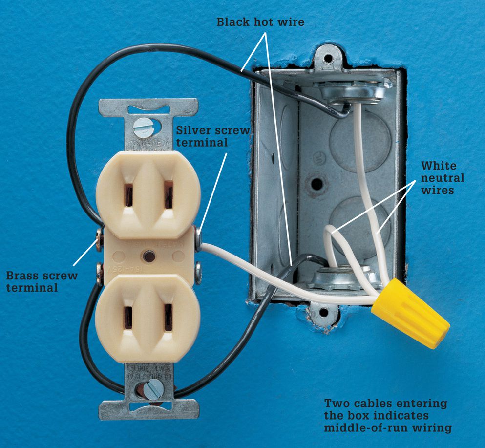
Receptacles are wired as either end-of-run or middle-of-run. These two basic configurations are easily identified by counting the number of cables entering the receptacle box. End-of-run wiring has only one cable, indicating that the circuit ends. Middle-of-run wiring has two cables, indicating that the circuit continues on to other receptacles, switches, or fixtures.
A split-circuit receptacle is shown on the next page. Each half of a split-circuit receptacle is wired to a separate circuit. This allows two appliances of high wattage to be plugged into the same receptacle without blowing a fuse or tripping a breaker. This wiring configuration is similar to a receptacle that is controlled by a wall switch. Code requires a switch-controlled receptacle in most rooms that do not have a built-in light fixture operated by a wall switch.
Split-circuit and switch-controlled receptacles are connected to two hot wires, so use caution during repairs or replacements. Make sure the connecting tab between the hot screw terminals is removed.
Two-slot receptacles are common in older homes. There is no grounding wire attached to the receptacle, but the metal box may be grounded with armored cable or metal conduit. Tamper-resistant receptacles are now required in all new residential installations.
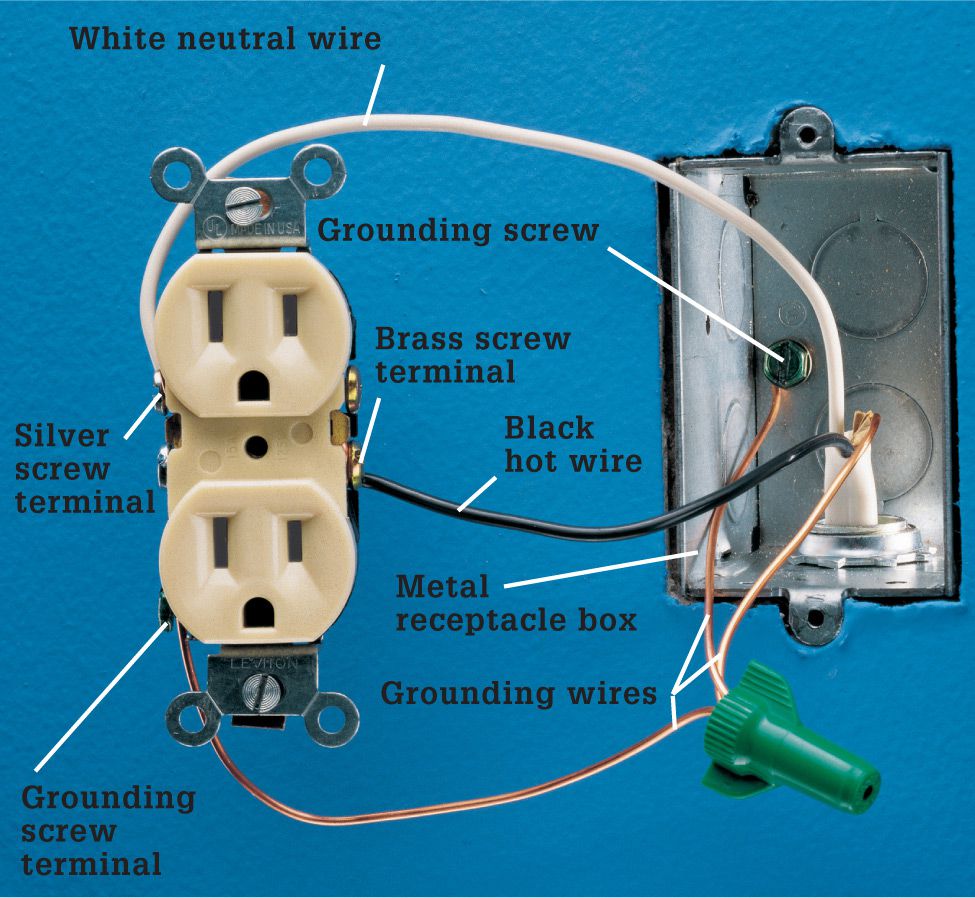
A single cable entering the box indicates end-of-run wiring. The black hot wire is attached to a brass screw terminal, and the white neutral wire is connected to a silver screw terminal. If the box is metal, the grounding wire is pigtailed to the grounding screws of the receptacle and the box. In a plastic box, the grounding wire is attached directly to the grounding screw terminal of the receptacle.
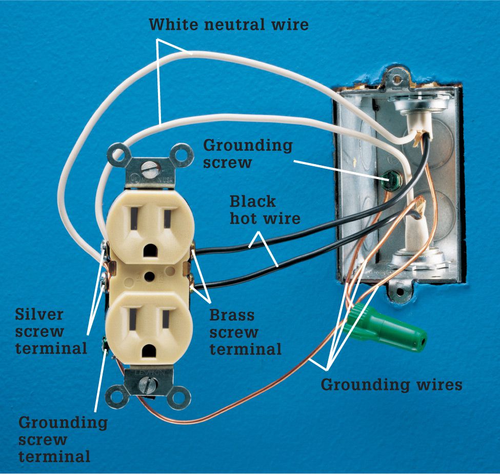
Two cables entering the box indicate middle-of-run wiring. Black hot wires are connected to brass screw terminals and white neutral wires to silver screw terminals. The grounding wire is pigtailed to the grounding screws of the receptacle and the box.
A split-circuit receptacle (technically a multi-wire branch circuit) is attached to a black hot wire, a red hot wire, a white neutral wire, and a bare grounding wire. The wiring is similar to a switch-controlled receptacle. The hot wires are attached to the brass screw terminals, and the connecting tab or fin between the brass terminals is removed. The white wire is attached to a silver screw terminal, and the connecting tab on the neutral side remains intact. The grounding wire is pigtailed to the grounding screw terminal of the receptacle and to the grounding screw attached to the box.
A two-slot receptacle is often found in older homes. The black hot wires are connected to the brass screw terminals, and the white neutral wires are pigtailed to a silver screw terminal. Two-slot receptacles may be replaced with three-slot types, but only if a means of grounding exists at the receptacle box. In some municipalities, you may replace a two-slot receptacle with a GFCI receptacle as long as the receptacle has a sticker that reads “No equipment ground.”
![]() How to Install a New Receptacle
How to Install a New Receptacle
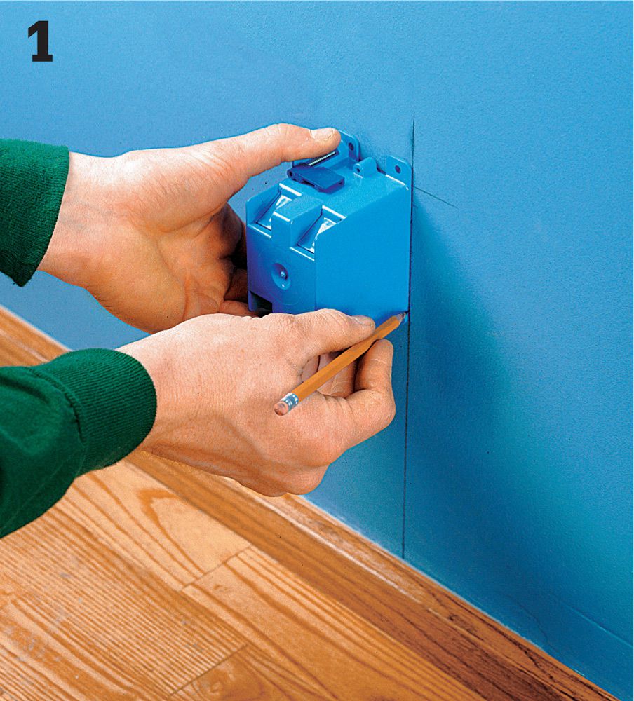
Position the new old work box on the wall and trace around it. Consider the location of hidden utilities within the wall before you cut.
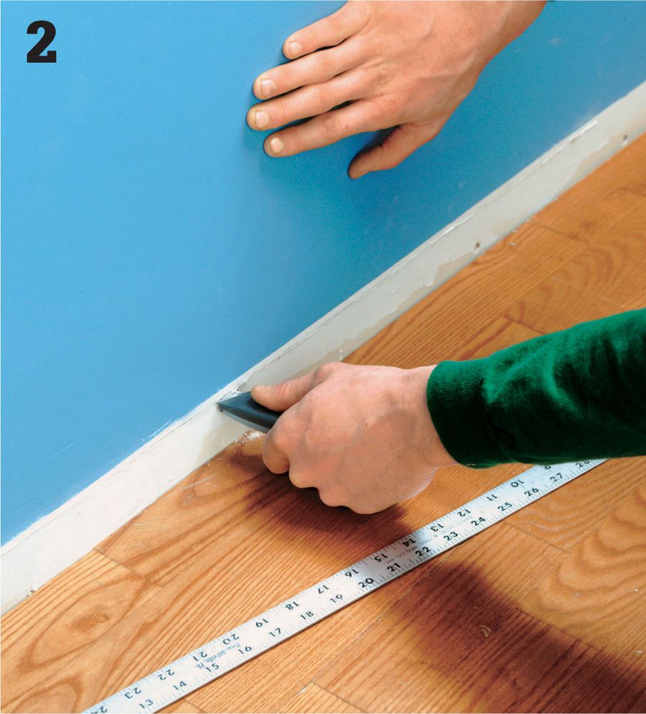
Remove baseboard between the new and existing receptacle. Cut away the drywall about 1" below the baseboard with a jigsaw, wallboard saw, or utility knife.
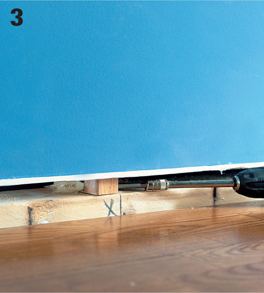
Drill a 5/8" hole in the center of each stud along the opening between the two receptacles. A drill bit extender or a flexible drill bit will allow you a better angle and make drilling the holes easier.
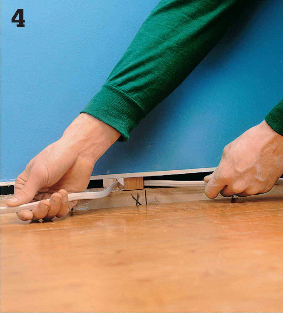
Run the branch cable through the holes from the new location to the existing receptacle. Staple the cable to the stud below the box. Install a metal nail plate on the front edge of each stud that the cable routes through.
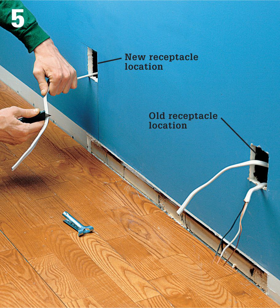
Turn off the power at the panel and test for power. Remove the old receptacle and its box, and pull the new branch cable up through the hole. Remove sheathing and insulation from both ends of the new cable.
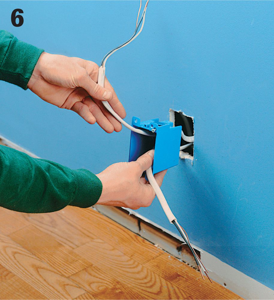
Thread the new and old cables into an old work box large enough to contain the added wires and clamp the cables. Fit the box into the old hole and attach it.
Reconnect the old receptacle by connecting its neutral, hot, and grounding screws to the new branch cable and the old cable from the panel with pigtails.
Pull the cable through another old work box for the new receptacle. Secure the cable and install the box. Connect the new receptacle to the new branch cable. Insert the receptacle into the box and attach the receptacle and cover plate with screws. Patch the opening with 1/2"-thick wood strips or drywall. Reattach the baseboard to the studs.
![]() GFCI Receptacles
GFCI Receptacles
The ground-fault circuit interrupter (GFCI) protects against electrical shock caused by a faulty appliance or a worn cord or plug. It senses small changes in current flow and can shut off power in as little as 1/40 of a second. GFCIs can be a circuit breaker and protect the circuit from the panel. Often, however, they are receptacles that protect one receptacle and may protect other receptacles and light fixtures downstream.
GFCIs are now required in bathrooms, kitchens, garages, crawl spaces, unfinished basements, and outdoor receptacle locations. Consult your local codes for any requirements regarding the installation of GFCIs. Most GFCI receptacles use standard screw terminal connections, but some have wire leads and are attached with wire connectors. Because the body of a GFCI receptacle is larger than a standard receptacle, small, crowded electrical boxes may need to be replaced with more spacious boxes.
Because the GFCI is so sensitive, it is most effective when wired to protect a single location. The more receptacles any one GFCI protects, the more susceptible it is to “phantom tripping,” shutting off power because of tiny, normal fluctuations in current flow. GFCI receptacles installed in outdoor locations must be rated for outdoor use and weather resistance (WR) along with ground fault protection.
Tools & Materials ![]()
Circuit tester
Screwdriver
Wire connectors
Masking tape
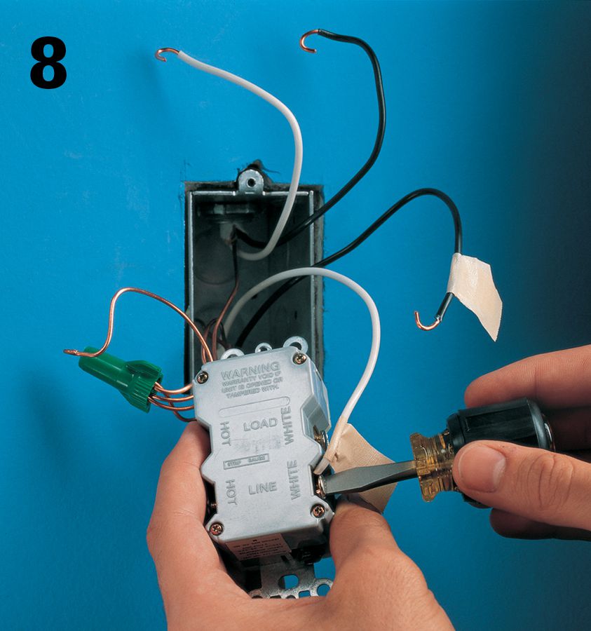
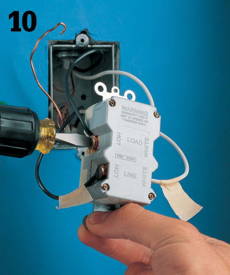
A GFCI wired for single-location protection (shown from the back) has hot and neutral wires connected only to the screw terminals marked LINE. A GFCI connected for single-location protection may be wired as either an end-of-run or middle-of-run configuration.
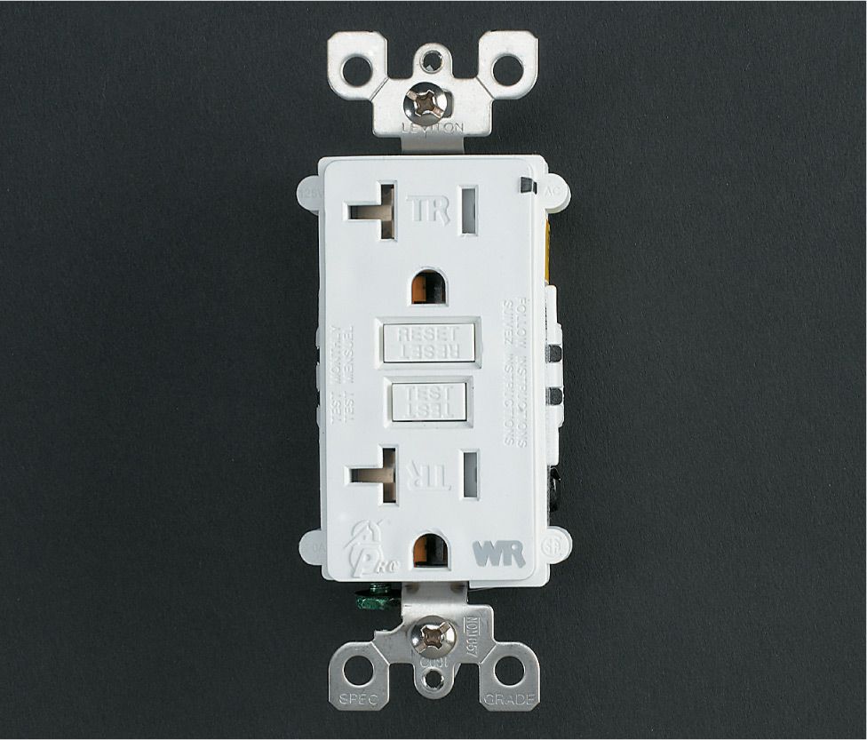
Modern GFCI receptacles have tamper-resistant slots. Look for a model that’s rated “WR” (for weather resistance) if you’ll be installing it outdoors or in a wet location.
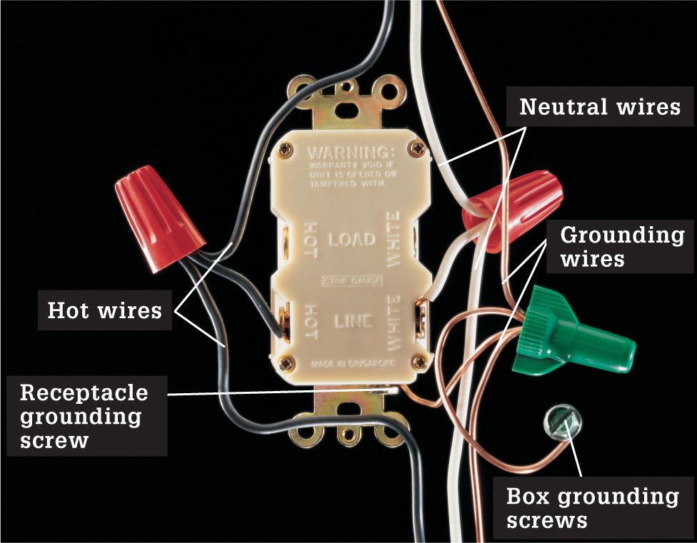
A GFCI wired for multiple-location protection (shown from the back) has one set of hot and neutral wires connected to the LINE pair of screw terminals and the other set connected to the LOAD pair of screw terminals. A GFCI receptacle connected for multiple-location protection may be wired only as a middle-of-run configuration.
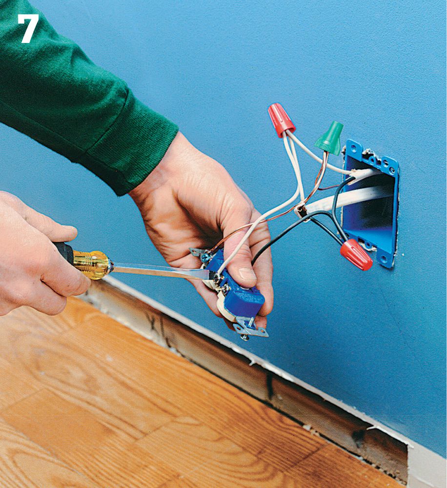
![]() How to Install a GFCI for Single-Location Protection
How to Install a GFCI for Single-Location Protection
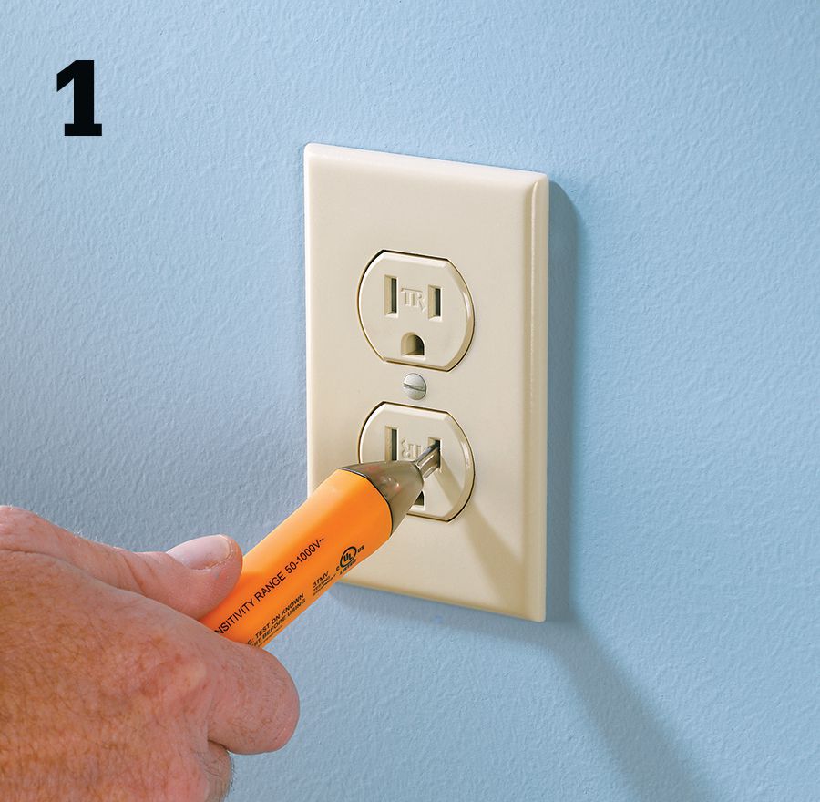
Shut off power to the receptacle at the panel. Test for power with a neon circuit tester. Be sure to check both halves of the receptacle.
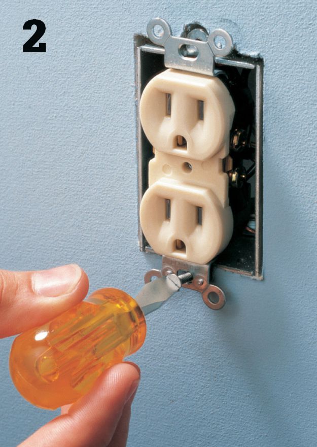
Remove the cover plate. Loosen mounting screws, and gently pull the receptacle from the box. Do not touch wires. Confirm power is off with a circuit tester.
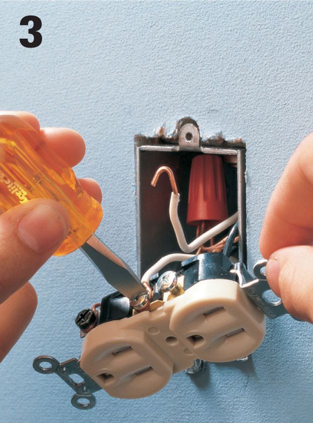
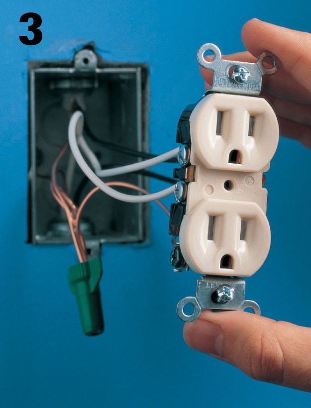
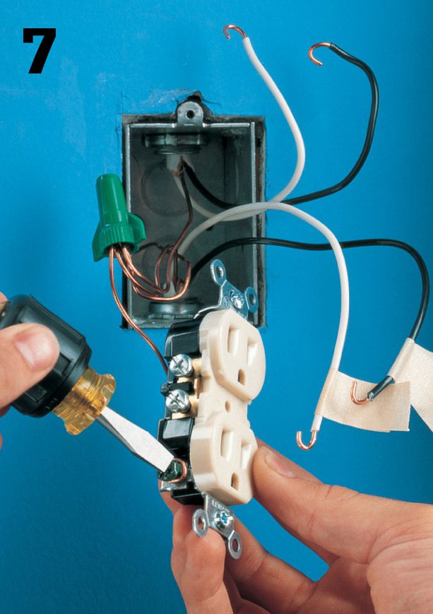
Disconnect all white neutral wires from the silver screw terminals of the old receptacle.
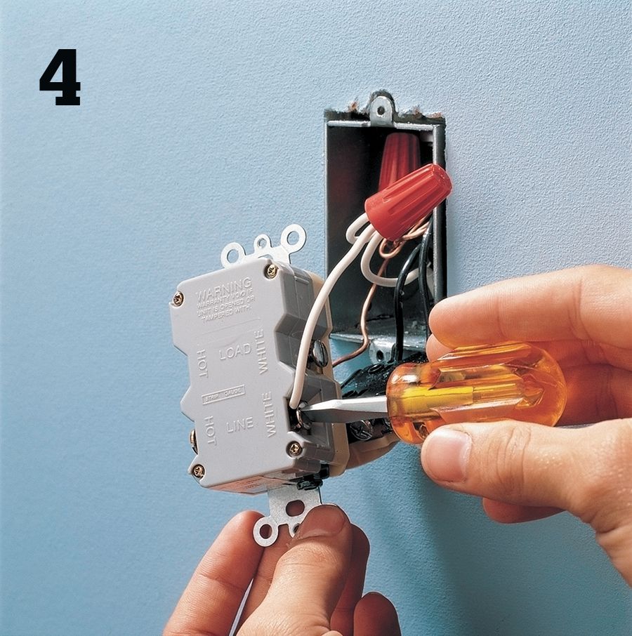
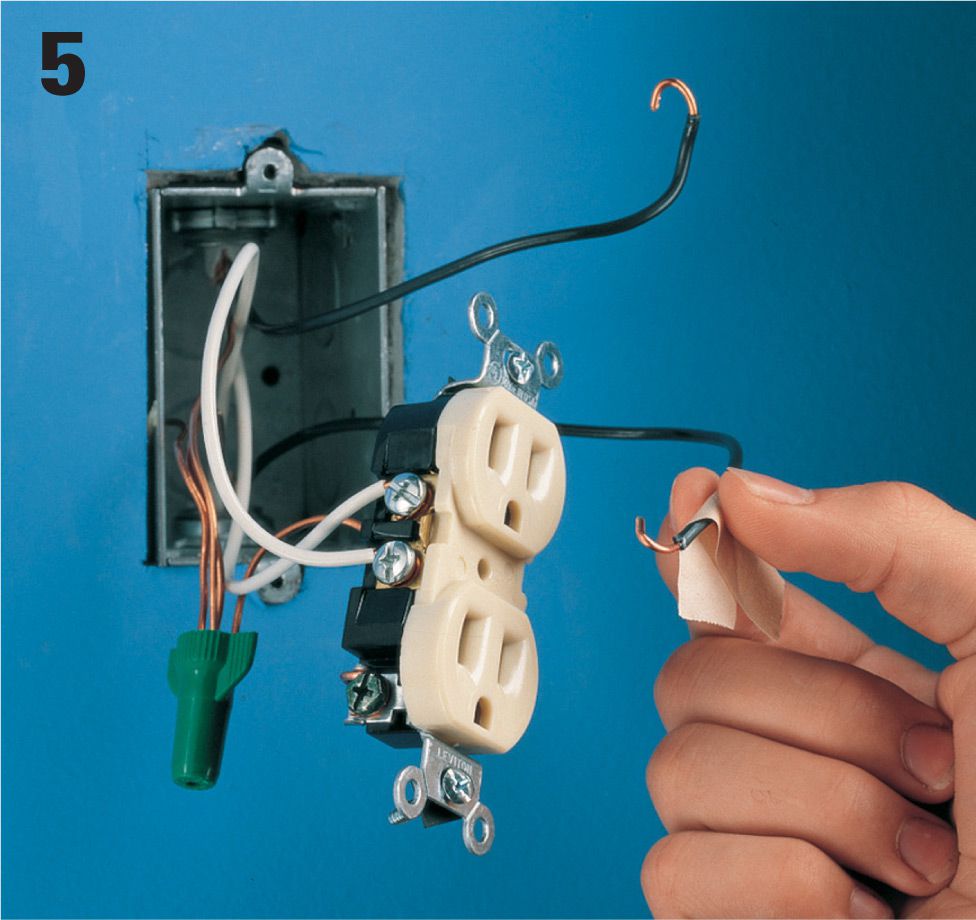
Pigtail all the white neutral wires together, and connect the pigtail to the terminal marked WHITE LINE on the GFCI (see photo on opposite page).
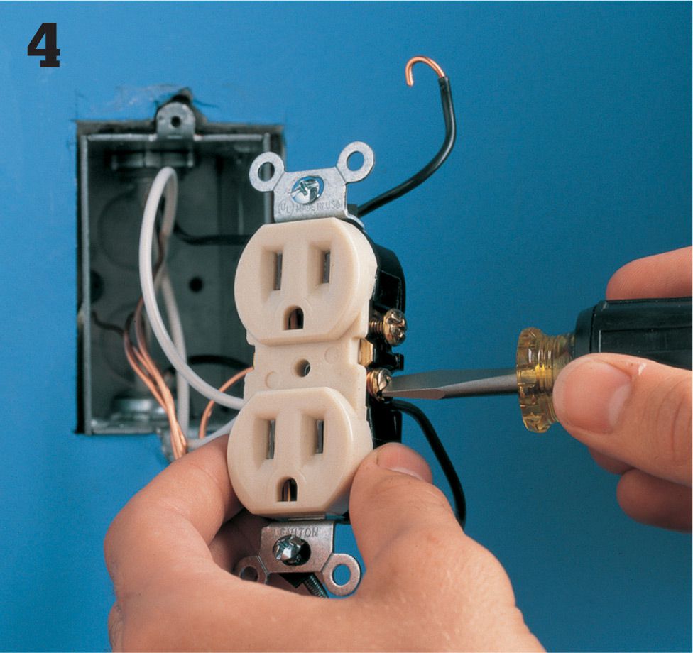
Disconnect all black hot wires from the brass screw terminals of the old receptacle. Pigtail these wires together, and connect them to the terminal marked HOT LINE on the GFCI.
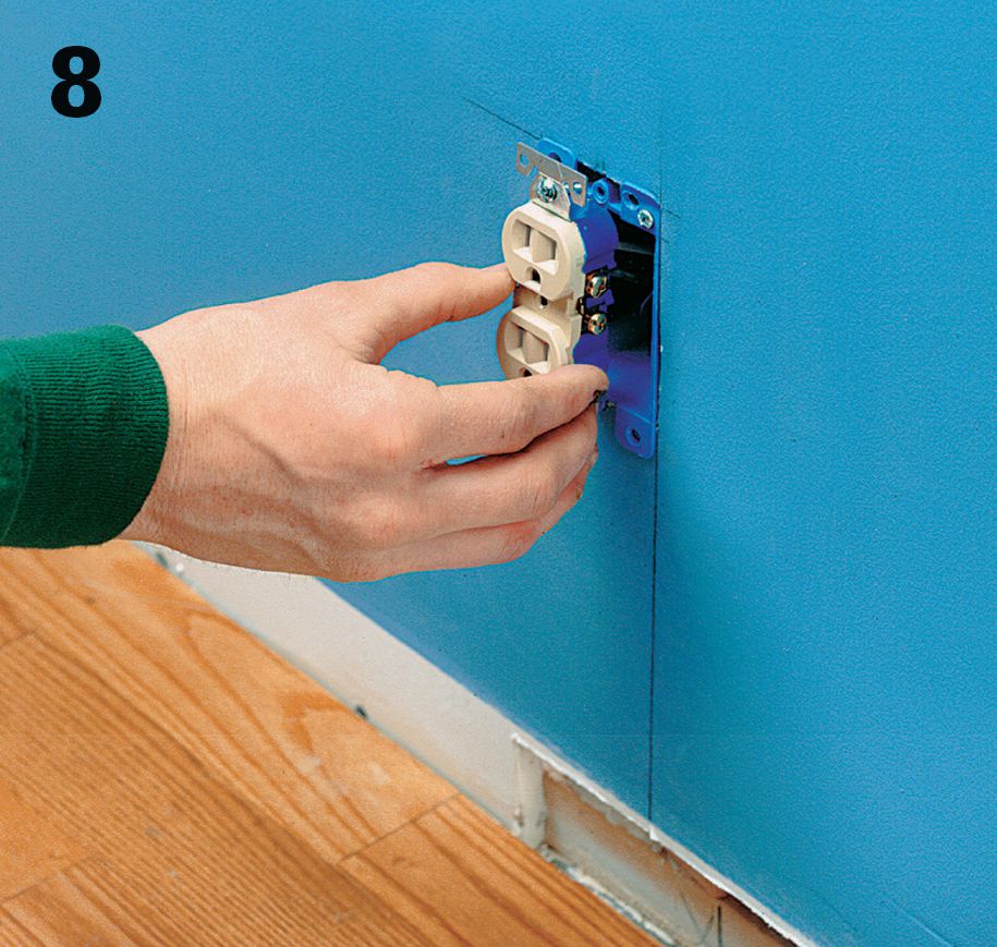
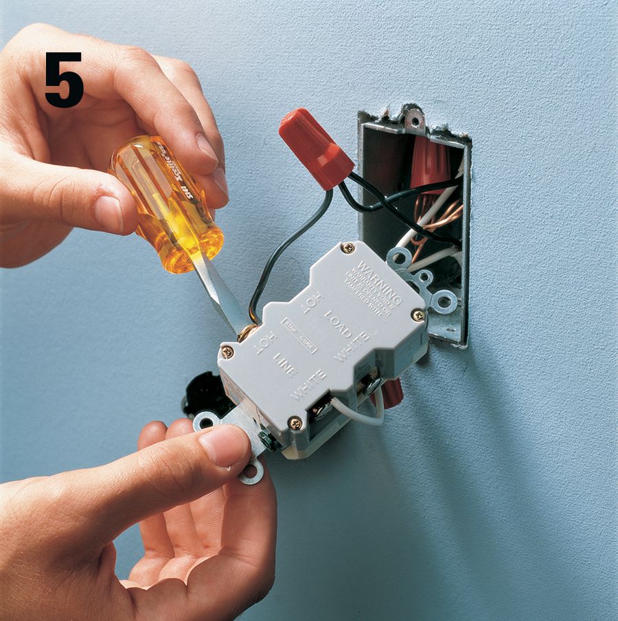
If a grounding wire is available, connect it to the green grounding screw terminal of the GFCI. Mount the GFCI in the receptacle box, and reattach the cover plate. Restore power, and test the GFCI according to the manufacturer’s instructions. If a grounding wire is not available, label the receptacle cover plate: “NO EQUIPMENT GROUND”.
![]() How to Install a GFCI for Multiple-Location Protection
How to Install a GFCI for Multiple-Location Protection
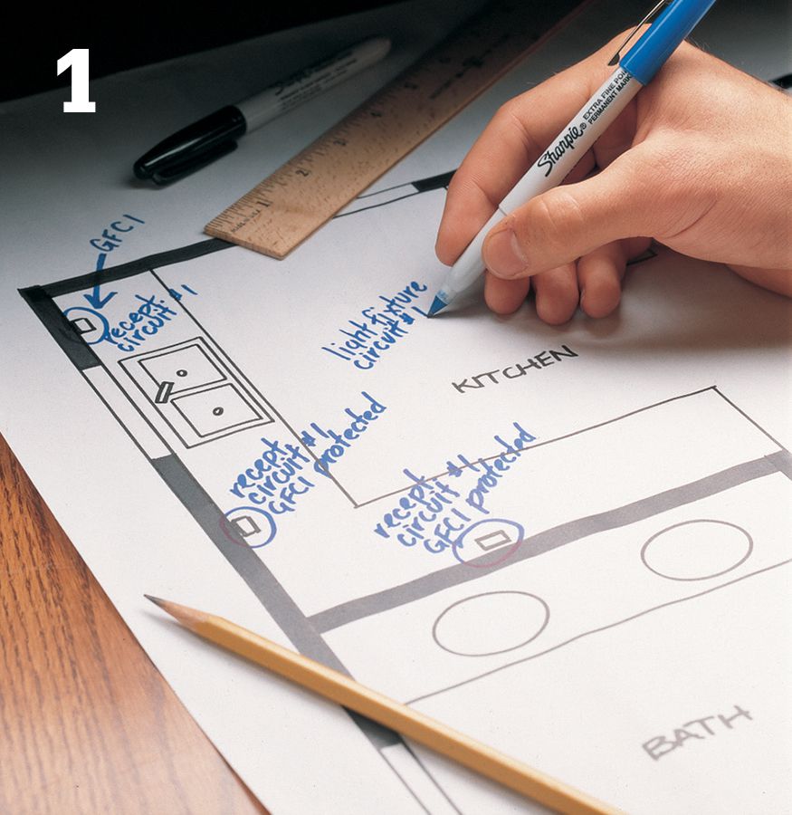
Use a map of your house circuits to determine a location for your GFCI. Indicate all receptacles that will be protected by the GFCI installation.
Turn off power to the correct circuit at the panel. Test all the receptacles in the circuit with a neon circuit tester to make sure the power is off. Always check both halves of each duplex receptacle.
Remove the cover plate from the receptacle that will be replaced with the GFCI. Loosen the mounting screws and gently pull the receptacle from its box. Take care not to touch any bare wires. Confirm the power is off with a neon circuit tester.
Disconnect all black hot wires. Carefully separate the hot wires and position them so that the bare ends do not touch anything. Restore power to the circuit at the panel. Determine which black wire is the feed wire by testing for hot wires. The feed wire brings power to the receptacle from the service panel. Use caution: This is a live wire test, during which the power is turned on temporarily.
When you have found the hot feed wire, turn off power at the panel. Identify the feed wire by marking it with masking tape.
Disconnect the white neutral wires from the old receptacle. Identify the white feed wire and label it with masking tape. The white feed wire will be the one that shares the same cable as the black feed wire.
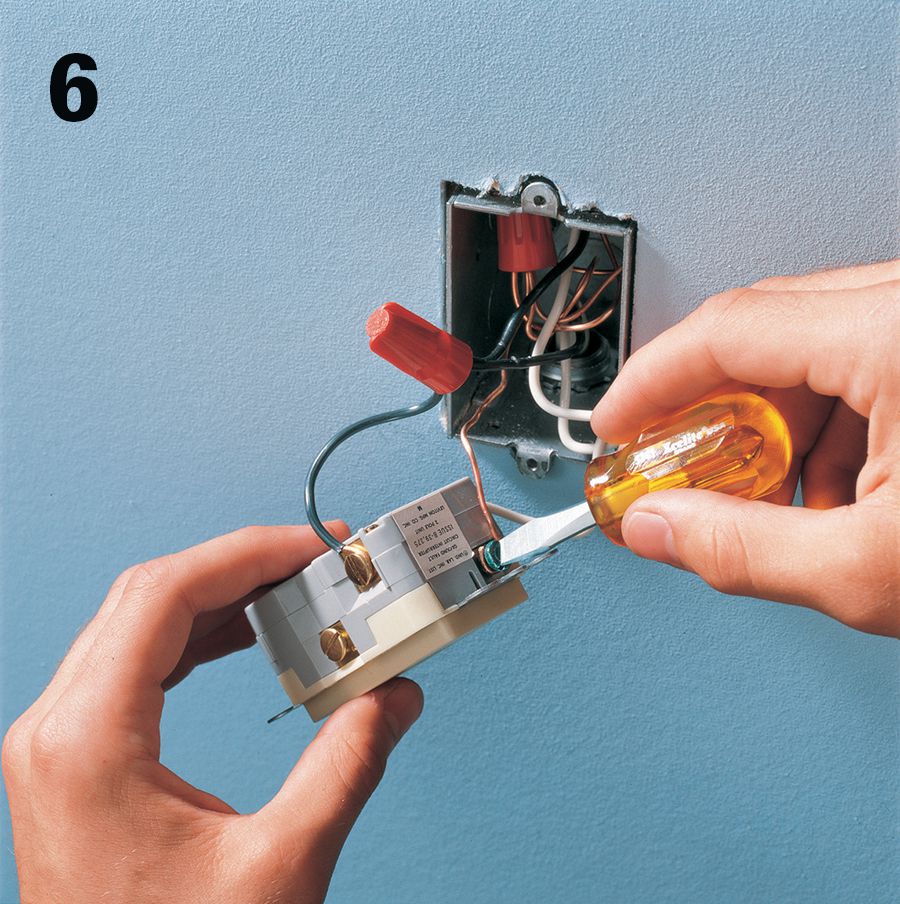
Disconnect the grounding wire from the grounding screw terminal of the old receptacle. Remove the old receptacle. Connect the grounding wire to the grounding screw terminal of the GFCI.
Connect the white feed wire to the terminal marked WHITE LINE on the GFCI. Connect the black feed wire to the terminal marked HOT LINE on the GFCI.
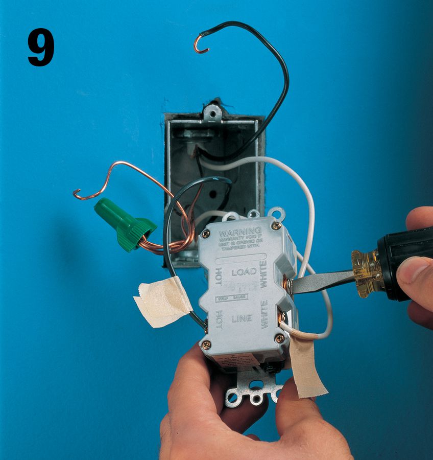
Connect the other white neutral wire to the terminal marked WHITE LOAD on the GFCI.
Connect the other black hot wire to the terminal marked HOT LOAD on the GFCI.
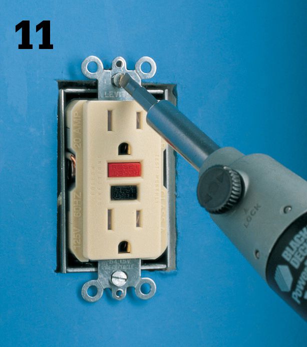
Carefully tuck all wires into the receptacle box. Mount the GFCI in the box and attach the cover plate. Turn on power to the circuit at the panel. Test the GFCI according to the manufacturer’s instructions.
![]() Testing Receptacles
Testing Receptacles
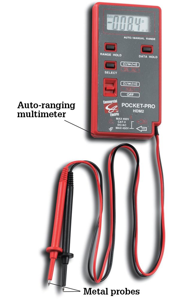
For testing receptacles and other devices for power, grounding, and polarity, neon circuit testers are inexpensive and easy to use. But they are less sensitive than auto-ranging multimeters. In some cases, neon testers won’t detect the presence of lower voltage in a circuit. This can lead you to believe that a circuit is shut off when it is not—a dangerous mistake. The small probes on a neon circuit tester also force you to get too close to live terminals and wires. For a quick check and confirmation, a neon circuit tester (or a plug-in tester) is adequate. But for the most reliable readings, buy and learn to use a multimeter.
The best multimeters are auto-ranging models with a digital readout. Unlike manual multimeters, auto-ranging models do not require you to preset the voltage range to get an accurate reading. Unlike neon testers, multimeters may be used for a host of additional diagnostic functions such as testing fuses, measuring battery voltage, testing internal wiring in appliances, and checking light fixtures to determine if they’re functional.
Tools & Materials ![]()
Multimeter
Touchless circuit tester
Plug-in tester
Screwdriver
![]() How to Use a Plug-in Tester
How to Use a Plug-in Tester
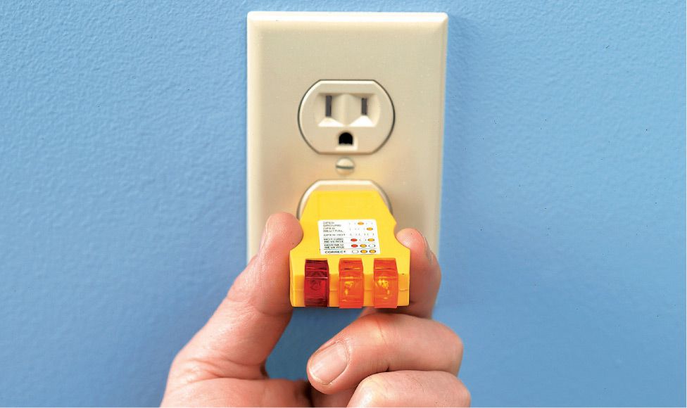
Use a plug-in tester to test a three-slot receptacle. With the power on, insert the tester into the suspect outlet. The face of the tester has three colored lights that will light up in different combinations, according to the outlet’s problem. A reference chart is provided with the tester, and there may be a chart on the tester itself. These testers are useful, but they do not test for all wiring errors.
![]() How to Test Quickly for Power
How to Test Quickly for Power
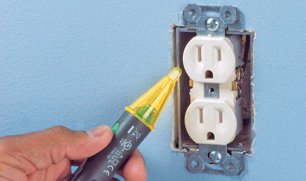
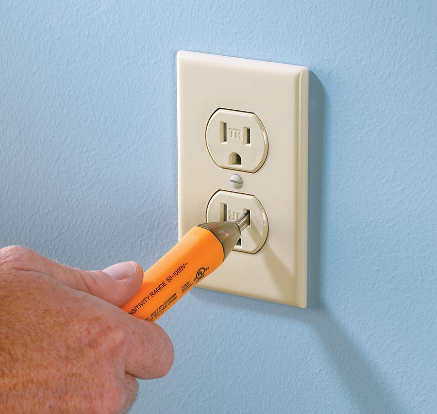
Use a touchless circuit tester to verify that power is not flowing to a receptacle. Using either a no-touch sensor or a probe-style circuit tester, test the receptacle for current before you remove the cover plate. Once the plate is removed, double-check at the terminals to make sure there is no current.
![]() How to Test a Receptacle with a Multimeter
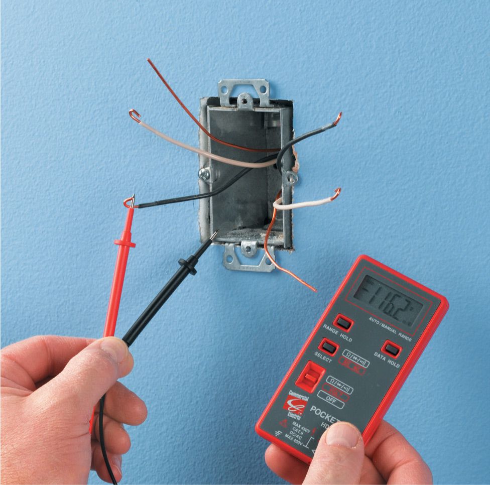
How to Test a Receptacle with a Multimeter
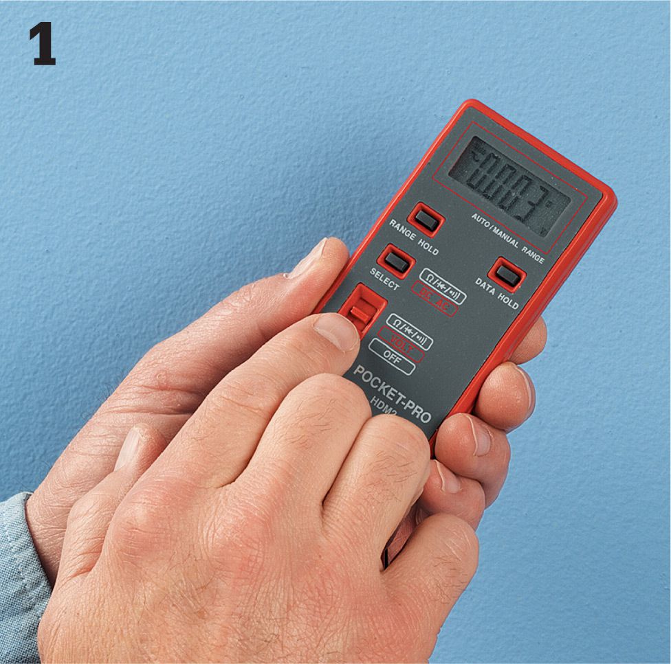
Set the selector dial for alternating-current voltage. Plug the black probe lead into the common jack (labeled COM) on the multimeter. Plug the red probe lead into the V-labeled jack.
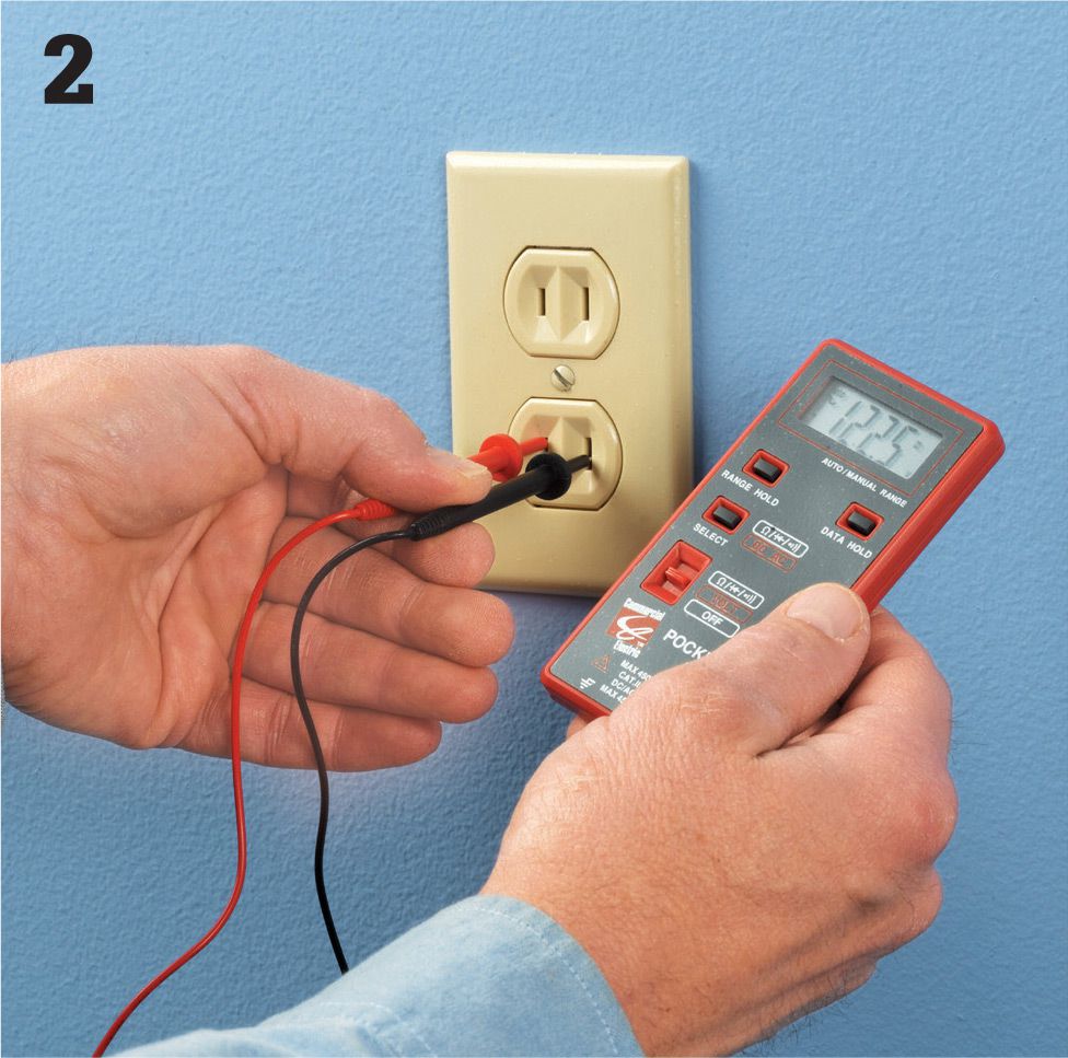
Insert the test ends of the probe into the receptacle slots. It does not make a difference which probe goes into which slot as long as they’re in the same receptacle. If power is present and flowing normally, you will see a voltage reading on the readout screen.
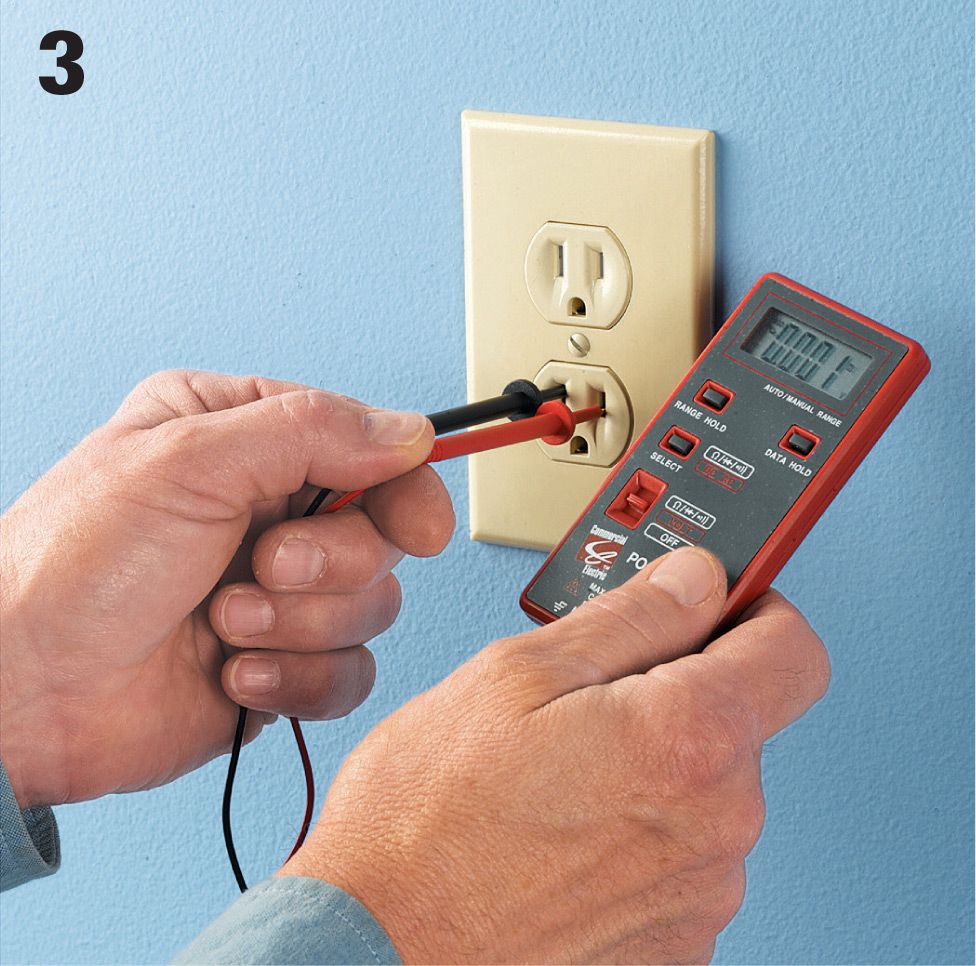
If the multimeter reads 0 or gives a very low reading (less than 1 or 2 volts), power is not present in the receptacle and it is safe to remove the cover plate and work on the fixture (although it’s always a good idea to confirm your reading by touching the probes directly to the screw terminals on the receptacles).
Option: When a receptacle or switch is in the middle of a circuit, it is difficult to tell which wires are carrying current. Use a multimeter to check. With power off, remove the receptacle and separate the wires. Restore power. Touch one probe to the bare ground or the grounded metal box and touch the other probe to the end of each wire. The wire that shows current on the meter is hot.