The Complete Guide to Wiring, Updated 6th Edition: Current with 2014-2017 Electrical Codes - Black & Decker, Cool Springs Press (2014)
Chapter 3. Boxes & Panels
All wiring connections must be housed within a box that is accessible. The box may be as simple as a small handy box for making a splice or as complex as a 200-amp main service panel. It is typically rectangular, square, round, or octagonal, but be aware that the boxes are shaped as they are for specific reasons, so make sure you are using the right one for the job.
Installing a box that is too small is an extremely common wiring mistake that is easy to understand: small boxes cost less. But they are not one-size fits all. The smallest common boxes, called handy boxes, may be used only for a single device (such as a switch or receptacle) with no more than three conductors. Be sure to refer to a box fill chart (see page 60) to learn which size and shape box is required for your job.
Electrical panels function like other electrical boxes insofar as they house connections, but they also house breakers or fuses and other parts that transmit power from the service entry to the individual circuits. Subpanels are smaller electrical panels that perform the same function but are supplied by the main service panel so they can distribute power into multiple circuits in a remote spot.
In this chapter:
![]() Electrical Boxes
Electrical Boxes
![]() Installing Boxes
Installing Boxes
![]() Electrical Panels
Electrical Panels
![]() Electrical Boxes
Electrical Boxes
The National Electrical Code requires that wire connections and cable splices be contained inside an approved metal or plastic box. The box shields framing members and other flammable materials from electrical sparks and protects people from being shocked.
Electrical boxes come in several shapes. Rectangular and square boxes are used for switches and receptacles. Rectangular (2 × 3") boxes are used for single switches or duplex receptacles. Square (4 × 4") boxes are used any time it is convenient for two switches or receptacles to be wired, or “ganged,” in one box. Octagonal electrical boxes contain wire connections for ceiling fixtures.
Electrical boxes are available in different depths. A box must be deep enough so a switch or receptacle can be removed or installed easily without crimping and damaging the circuit wires. The box must also be large enough to safely dissipate the heat from wires, switches, and receptacles. This is an important fire safety rule. Replace an undersized box with a larger box using the Electrical Box Fill Chart (right) as a guide.
In addition to the maximum box fill allowed by the chart, the area of all wires, taps, and splices should not exceed 75% of the box area. The NEC also says that all electrical boxes must remain accessible. Never cover an electrical box with drywall, paneling, or wallcoverings.
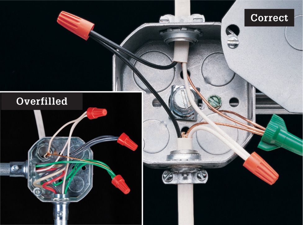
Octagonal boxes usually contain wire connections for ceiling fixtures. Because the ceiling fixture attaches directly to the box, the box should be anchored firmly to a framing member. A properly installed octagonal box can support a ceiling fixture weighing up to 35 pounds. Any box must be covered with a tightly fitting cover plate, and the box must not have open knockouts. Do not overfill the box (inset).
Electrical Box Fill Chart ![]()
|
Junction Boxes |
|
|
Box size and shape |
4 × 1 1/4" R or O |
|
Maximum number of conductors permitted (see Notes below) |
|
|
8 |
18 AWG |
|
7 |
16 AWG |
|
6 |
14 AWG |
|
5 |
12 AWG |
|
Junction Boxes |
|
|
Box size and shape |
4 × 1 1/2" R or O |
|
Maximum number of conductors permitted (see Notes below) |
|
|
10 |
18 AWG |
|
8 |
16 AWG |
|
7 |
14 AWG |
|
6 |
12 AWG |
|
Junction Boxes |
|
|
Box size and shape |
4 × 2 1/8" R or O |
|
Maximum number of conductors permitted (see Notes below) |
|
|
14 |
18 AWG |
|
12 |
16 AWG |
|
10 |
14 AWG |
|
9 |
12 AWG |
|
Junction Boxes |
|
|
Box size and shape |
4 × 1 1/4" S |
|
Maximum number of conductors permitted (see Notes below) |
|
|
12 |
18 AWG |
|
10 |
16 AWG |
|
9 |
14 AWG |
|
8 |
12 AWG |
|
Junction Boxes |
|
|
Box size and shape |
4 × 1 1/2" S |
|
Maximum number of conductors permitted (see Notes below) |
|
|
14 |
18 AWG |
|
12 |
16 AWG |
|
10 |
14 AWG |
|
9 |
12 AWG |
|
Junction Boxes |
|
|
Box size and shape |
4 × 2 1/8" S |
|
Maximum number of conductors permitted (see Notes below) |
|
|
20 |
18 AWG |
|
17 |
16 AWG |
|
15 |
14 AWG |
|
13 |
12 AWG |
|
Junction Boxes |
|
|
Box size and shape |
4 1 1/16 × 1 1/4" S |
|
Maximum number of conductors permitted (see Notes below) |
|
|
17 |
18 AWG |
|
14 |
16 AWG |
|
12 |
14 AWG |
|
11 |
12 AWG |
|
Junction Boxes |
|
|
Box size and shape |
4 1 1/16 × 1 1/2" S |
|
Maximum number of conductors permitted (see Notes below) |
|
|
19 |
18 AWG |
|
16 |
16 AWG |
|
14 |
14 AWG |
|
13 |
12 AWG |
|
Junction Boxes |
|
|
Box size and shape |
4 1 1/16 × 2 1/8" S |
|
Maximum number of conductors permitted (see Notes below) |
|
|
28 |
18 AWG |
|
24 |
16 AWG |
|
21 |
14 AWG |
|
18 |
12 AWG |
|
Device Boxes |
|
|
Box size and shape |
3 × 2 × 1 1/2" |
|
Maximum number of conductors permitted (see Notes below) |
|
|
5 |
18 AWG |
|
4 |
16 AWG |
|
3 |
14 AWG |
|
3 |
12 AWG |
|
Device Boxes |
|
|
Box size and shape |
3 × 2 × 2" |
|
Maximum number of conductors permitted (see Notes below) |
|
|
6 |
18 AWG |
|
5 |
16 AWG |
|
5 |
14 AWG |
|
4 |
12 AWG |
|
Device Boxes |
|
|
Box size and shape |
3 × 2 × 2 1/4" |
|
Maximum number of conductors permitted (see Notes below) |
|
|
7 |
18 AWG |
|
6 |
16 AWG |
|
5 |
14 AWG |
|
4 |
12 AWG |
|
Device Boxes |
|
|
Box size and shape |
3 × 2 × 2 1/2" |
|
Maximum number of conductors permitted (see Notes below) |
|
|
8 |
18 AWG |
|
7 |
16 AWG |
|
6 |
14 AWG |
|
5 |
12 AWG |
|
Device Boxes |
|
|
Box size and shape |
3 × 2 × 2 3/4" |
|
Maximum number of conductors permitted (see Notes below) |
|
|
9 |
18 AWG |
|
8 |
16 AWG |
|
7 |
14 AWG |
|
6 |
12 AWG |
|
Device Boxes |
|
|
Box size and shape |
3 × 2 × 3 1/2" |
|
Maximum number of conductors permitted (see Notes below) |
|
|
12 |
18 AWG |
|
10 |
16 AWG |
|
9 |
14 AWG |
|
8 |
12 AWG |
|
Device Boxes |
|
|
Box size and shape |
4 × 2 1/8 × 1 1/2" |
|
Maximum number of conductors permitted (see Notes below) |
|
|
6 |
18 AWG |
|
5 |
16 AWG |
|
5 |
14 AWG |
|
4 |
12 AWG |
|
Device Boxes |
|
|
Box size and shape |
4 × 2 1/8 × 1 7/8" |
|
Maximum number of conductors permitted (see Notes below) |
|
|
8 |
18 AWG |
|
7 |
16 AWG |
|
6 |
14 AWG |
|
5 |
12 AWG |
|
Device Boxes |
|
|
Box size and shape |
4 × 2 1/8 × 2 1/8" |
|
Maximum number of conductors permitted (see Notes below) |
|
|
9 |
18 AWG |
|
8 |
16 AWG |
|
7 |
14 AWG |
|
6 |
12 AWG |
Notes:
✵ R = Round; O = Octagonal; S = Square or rectangular
✵ Each hot or neutral wire entering the box is counted as one conductor.
✵ Grounding wires are counted as one conductor in total—do not count each one individually.
✵ Raceway fittings and external cable clamps do not count. Internal cable connectors and straps count as either half or one conductor, depending on type.
✵ Devices (switches and receptacles mainly) each count as two conductors.
✵ When calculating total conductors, any nonwire components should be assigned the gauge of the largest wire in the box.
✵ For wire gauges not shown here, contact your local electrical inspections office.
![]() Common Electrical Boxes
Common Electrical Boxes
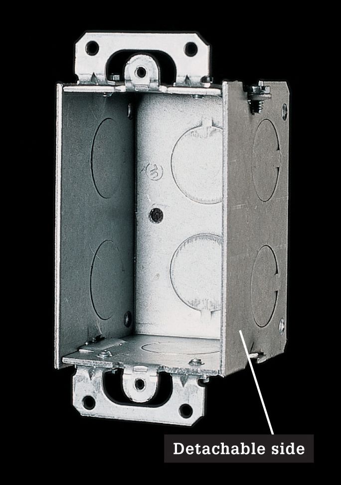
Rectangular boxes are used with wall switches and duplex receptacles. Single-size rectangular boxes (shown above) may have detachable sides that allow them to be ganged together to form double-size boxes.
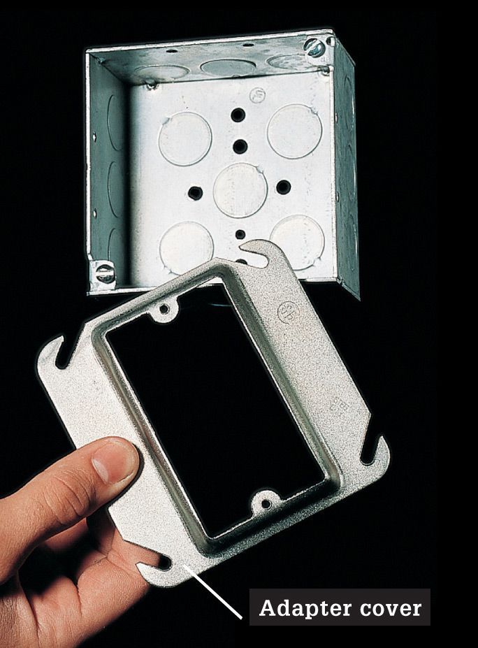
Square 4" × 4" boxes are large enough for most wiring applications. They are used for cable splices and ganged receptacles or switches. To install one switch or receptacle in a square box, use an adapter cover.
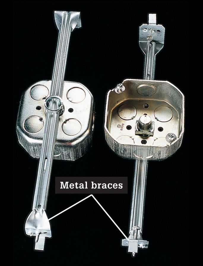
Braced octagonal boxes fit between ceiling joists. The metal braces extend to fit any joist spacing and are nailed or screwed to framing members.
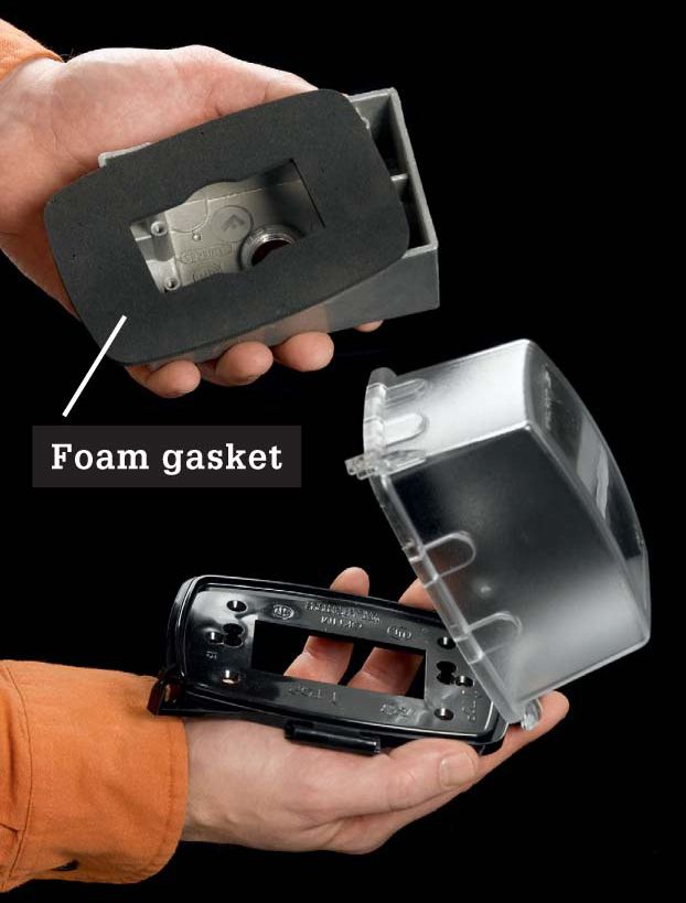
Outdoor boxes have sealed seams and foam gaskets to guard a switch or receptacle against moisture. Corrosion-resistant coatings protect all metal parts. Code compliant models include a watertight hood that protects even when the outlet is in use.
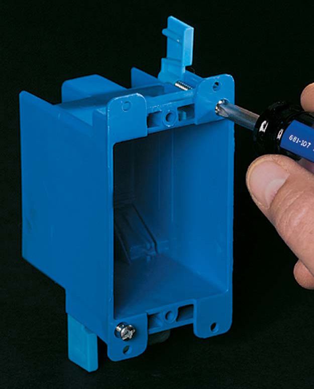
Old work boxes can be installed to upgrade older boxes or to allow you to add new additional receptacles and switches. One type (above) has built-in clamps that tighten against the inside of a wall and hold the box in place.
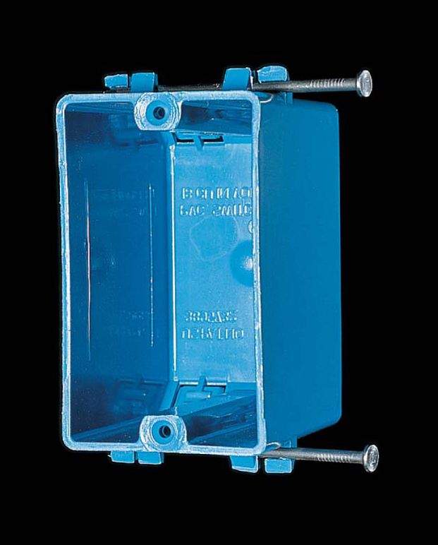
Plastic boxes are common in new construction. The box may include preattached nails for anchoring it to framing members. Wall switches must have grounding screws if installed in plastic boxes.
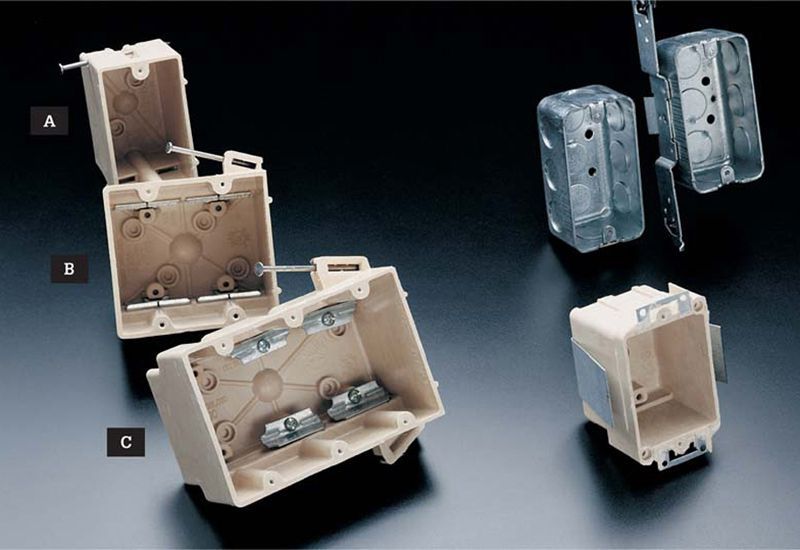
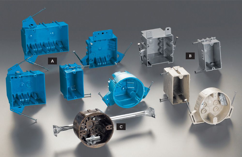
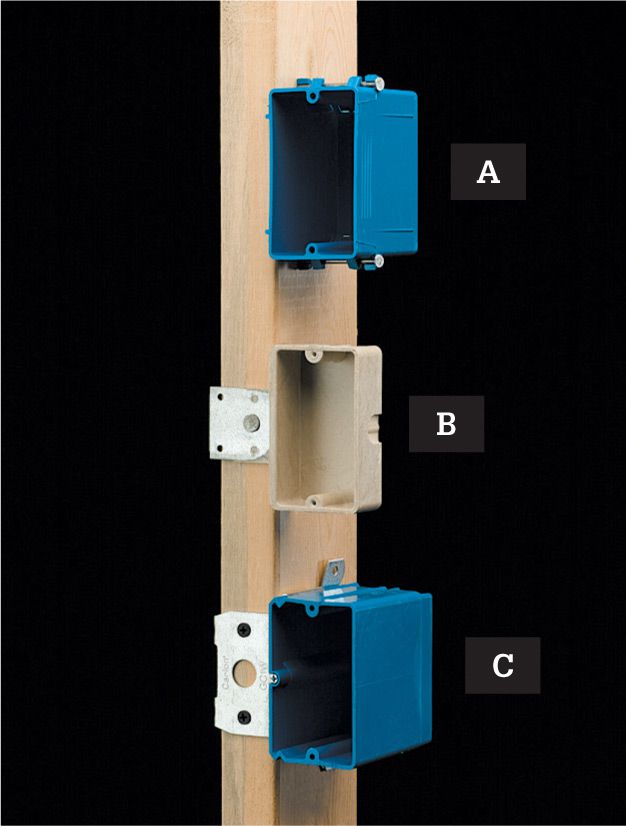
3 1/2-deep plastic boxes with preattached mounting nails are used for any wiring project protected by finished walls. Common styles include single-gang (A), double-gang (B), and triple-gang (C). Double-gang and triple-gang boxes require internal cable clamps. Metal boxes should be used for exposed indoor wiring, such as conduit installations in an unfinished basement. Metal boxes also can be used for wiring that will be covered by finished walls. Plastic retrofit boxes are used when a new switch or receptacle must fit inside a finished wall. Use internal cable clamps.
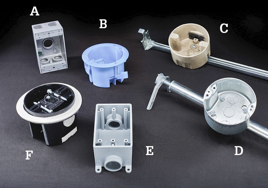
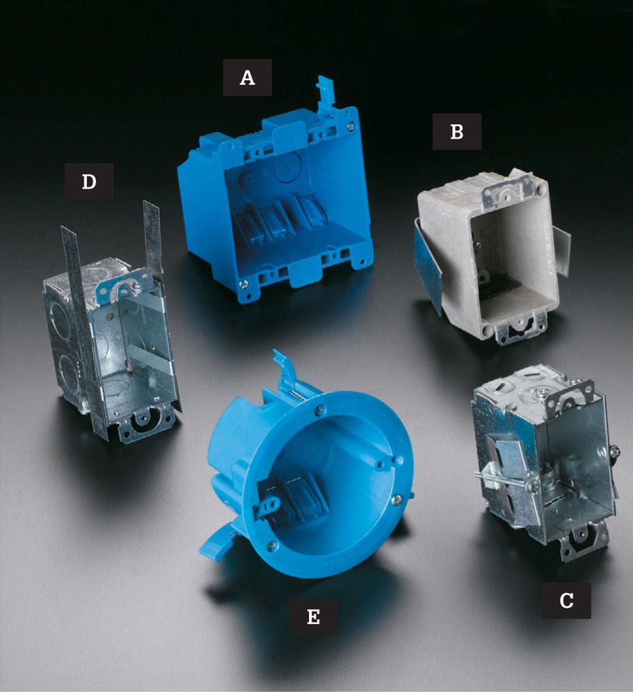
Additional electrical boxes include, cast aluminum box (A) for use with outdoor fixtures, including receptacles that are wired through metal conduit (these must have in-use covers if they house receptacles); old work ceiling box (B) used for light fixtures; light-duty ceiling fan box (C) with brace that spans ceiling joists; heavy-duty retrofit ceiling fan box (D) designed for retrofit; PVC box (E) for use with PVC conduit in indoor or outdoor setting; vapor-proof ceiling box with foam gasket (F).
Box Specifications ![]()
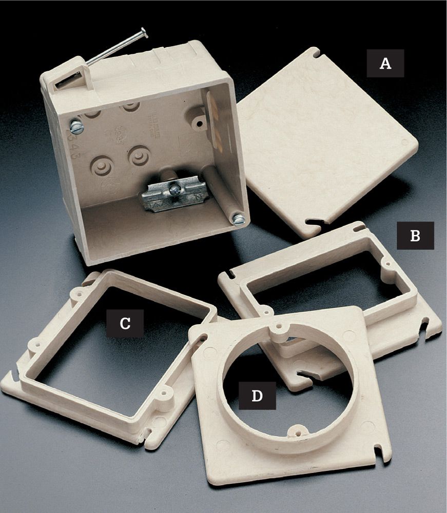
High-quality nonmetallic boxes are rigid and don’t contort easily. A variety of adapter plates are available, including junction box cover plate (A), single-gang (B), double-gang (C), and light fixture (D). Adapter plates come in several thicknesses to match different wall constructions.
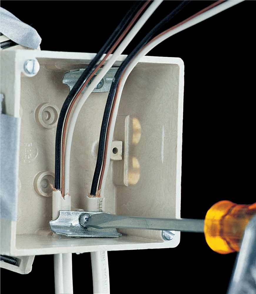
Boxes larger than 2 × 4" and all retrofit boxes must have internal cable clamps. After installing cables in the box, tighten the cable clamps over the cables so they are gripped firmly, but not so tightly that the cable sheathing is crushed.
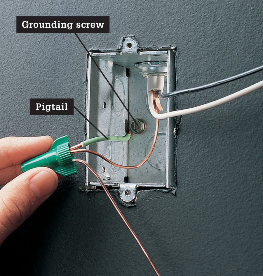
Metal boxes must be bonded to the circuit grounding system. Connect the circuit grounding wires to the box with a green insulated pigtail wire and wire connector (as shown) or with a grounding clip (page 38).
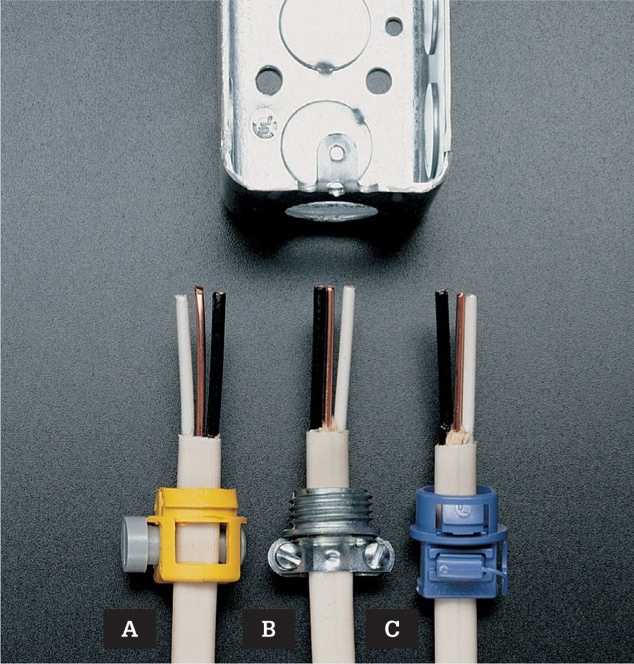
Cables entering a metal box must be clamped. A variety of clamps are available, including plastic clamps (A, C) and threaded metal clamps (B).
![]() Nonmetallic Boxes
Nonmetallic Boxes
Nonmetallic electrical boxes have taken over much of the do-it-yourself market. Most are sold prefitted with installation hardware—from metal wings to 10d common nails attached at the perfect angle for a nail-in box. The bulk of the nonmetallic boxes sold today are inexpensive blue PVC. You can also purchase heavier-duty fiberglass or thermoset plastic models that provide a nonmetallic option for installing heavier fixtures such as ceiling fans and chandeliers.
In addition to cost and availability, nonmetallic boxes hold a big advantage over metal boxes in that their resistance to conducting electricity will prevent a sparking short circuit if a hot wire contacts the box. Nonmetallic boxes generally are not approved for exposed areas, where they may be susceptible to damage. Their lack of rigidity also allows them to compress or distort, which can reduce the interior capacity beyond code minimums or make outlets difficult to attach.
Low cost is the primary reason that blue PVC nail-in boxes are so popular. Not only are they inexpensive, they also feature built-in cable clamps so you may not need to buy extra hardware to install them. The standard PVC nail-in box is prefitted with a pair of 10d common nails for attaching to exposed wall studs. These boxes, often called handy boxes, are too small to be of much use (see fill chart, page 62).
Nonmetallic boxes for home use include: Single-gang, double-gang, triple gang, and quad boxes (A); thermoset and fiberglass boxes for heavier duty (B); and round fixture boxes (C) for ceiling installation (nail-in and with integral metal bracket).
![]() Working With Nonmetallic Boxes
Working With Nonmetallic Boxes
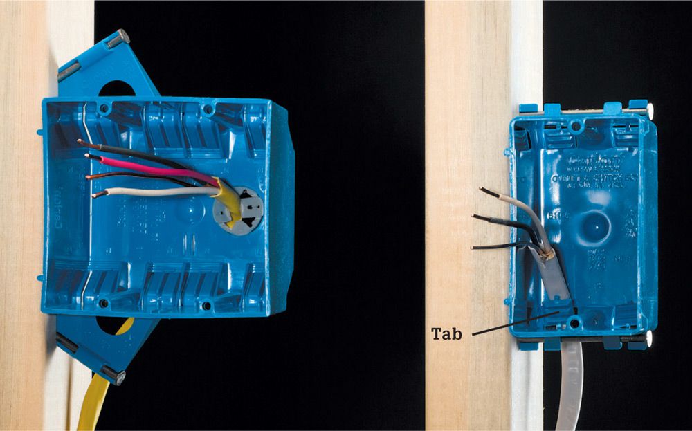
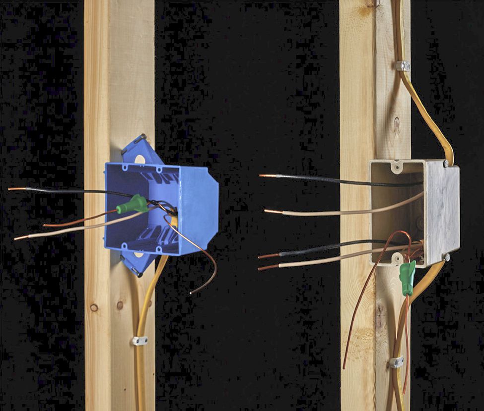
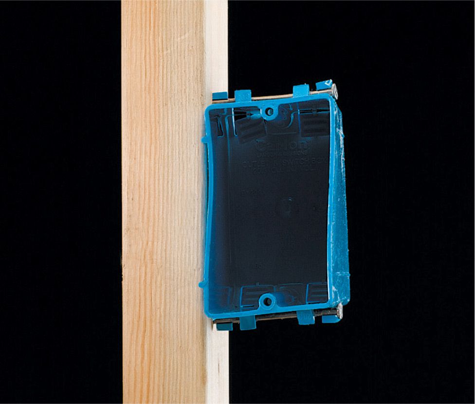
Do not break off the tabs that cover cable entry holes in plastic boxes. These are not knockouts as you would find in metal boxes. In single-gang boxes (right), the pressure from the tab is sufficient to secure the cable as long as it enters with sheathing intact and is stapled no more than 8" from the box. On larger boxes (left), you will find traditional knockouts intended to be used with plastic cable clamps that resemble metal cable clamps. Use these for heavier gauge cable and cable with more than three wires.
Nail-in boxes (A) are prefitted with 10d nails that are attached perpendicular to the face of single-gang boxes and at an inward angle for better gripping power on larger boxes. Side-mount boxes (B) feature a nailing plate that is attached to the front of the stud to automatically create the correct setback; adjustable side-mount boxes (C) are installed the same way but can be moved on the bracket.
Distortion can occur in nonmetallic boxes when nails or other fasteners are overdriven or installed at improper angles, or when the semiflexible boxes are compressed into improperly sized or shaped openings. This can reduce the box capacity and prevent devices and faceplates from fitting.
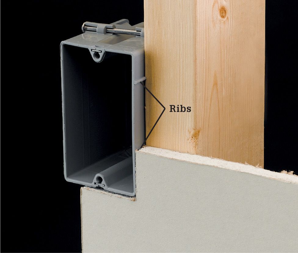
Integral ribs cast into many nonmetallic boxes are used to register the box against the wall studs so the front edges of the box will be flush with the wall surface after drywall is installed. Most are set for 1/2" drywall, but if your wall will be a different thickness you may be able to find a box with corresponding ribs. Otherwise, use a piece of the wallcovering material as a reference.
![]() Installing Boxes
Installing Boxes
Install electrical boxes for receptacles, switches, and fixtures only after your wiring project plan has been approved by your inspector. Use your wiring plan as a guide, and follow electrical code height and spacing guidelines when laying out box positions.
Always use the deepest electrical boxes that are practical for your installation. Using deep boxes ensures that you will meet code regulations regarding box volume and makes it easier to make the wire connections.
Some electrical fixtures, such as recessed light fixtures, electric heaters, and exhaust fans, have built-in wire connection boxes. Install the frames for these fixtures at the same time you are installing the other electrical boxes. The box heights recommended on the following pages are for most situations. Boxes heights for handicap accessible situations are different.
Electrical boxes in adjacent rooms should be positioned close together when they share a common wall and are controlled by the same circuit. This simplifies the cable installations and also reduces the amount of cable needed.
![]() Fixtures That Do Not Need Electrical Boxes
Fixtures That Do Not Need Electrical Boxes
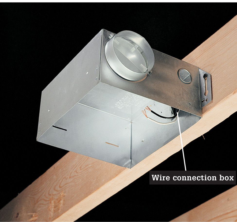
Recessed fixtures that fit inside wall cavities have built-in wire connection boxes and require no additional electrical boxes. Common recessed fixtures include electric blower-heaters (top image), bathroom vent fans (bottom image), and recessed light fixtures. Install the frames for these fixtures at the same time you are installing the other electrical boxes along the circuit. Surface-mounted fixtures such as electric baseboard heaters (pages 232 to 235) and under-cabinet fluorescent lights (pages 204 to 207) also have built-in wire connection boxes. These fixtures are not installed until it is time to make the final hookups.
![]() How to Install Electrical Boxes for Receptacles
How to Install Electrical Boxes for Receptacles
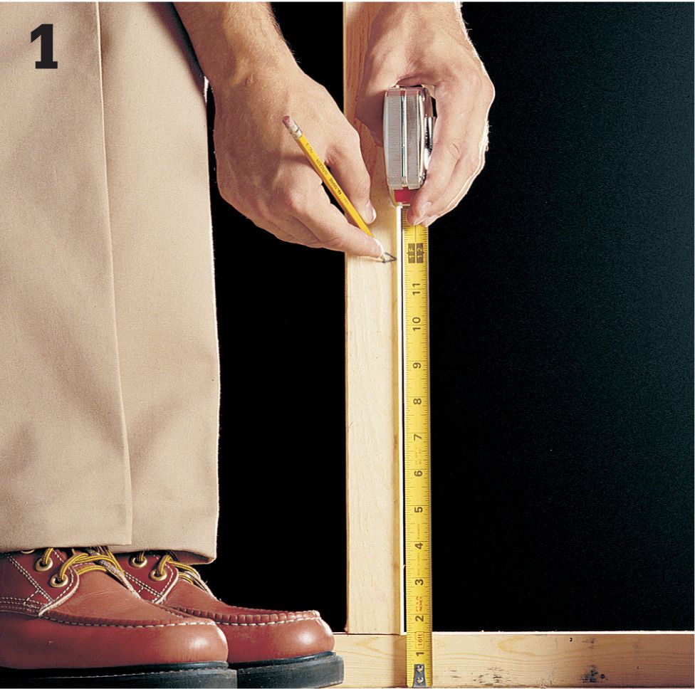
Mark the location of each box on studs. Standard receptacle boxes should be centered 12" above floor level. GFCI receptacle boxes in a bathroom should be mounted so they will be about 10" above the finished countertop.
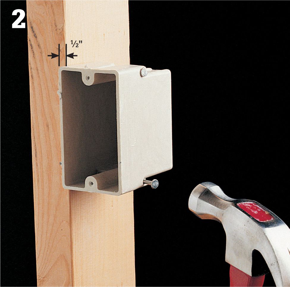
Position each box against a stud so the front face will be flush with the finished wall. For example, if you will be installing 1/2" drywall, position the box so it extends 1/2" past the face of the stud, plus the thickness of any additional material, such as tile. Anchor the box by driving the mounting nails into the stud.
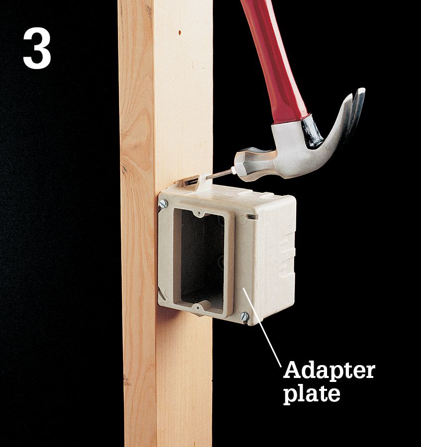
If installing square boxes, attach the adapter plates before positioning the boxes. Use adapter plates that match the thickness of the finished wall. Anchor the box by driving the mounting nails into the stud.
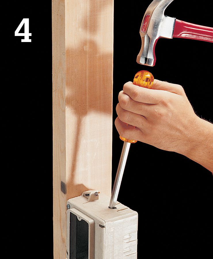
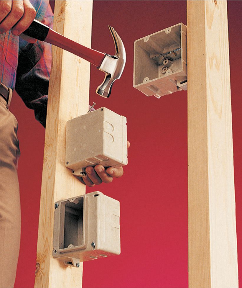
Open one knockout for each cable that will enter the box using a hammer and screwdriver. Always introduce the new cable through the knockout that is farthest way from the wall stud.
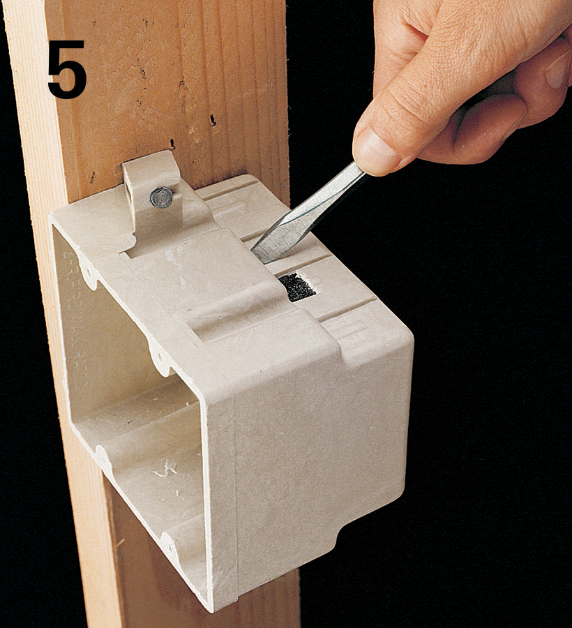
Break off any sharp edges that might damage vinyl cable sheathing by rotating a screwdriver in the knockout.
![]() How to Install Boxes for Light Fixtures
How to Install Boxes for Light Fixtures
Position the light fixture box for a vanity light above the frame opening for a mirror or medicine cabinet. Place the box for a ceiling light fixture in the center of the room. Position each box against a framing member so the front face will be flush with the finished wall or ceiling, and then anchor the box by driving the mounting nails into the framing.
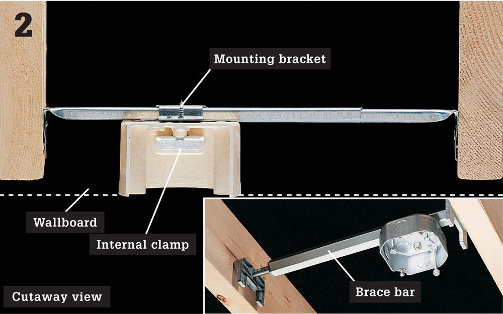
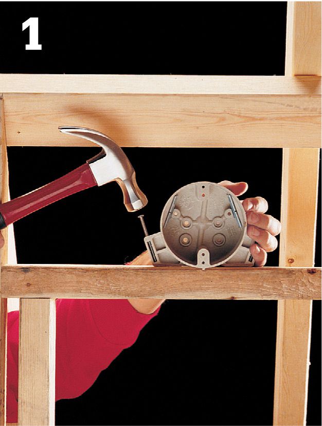
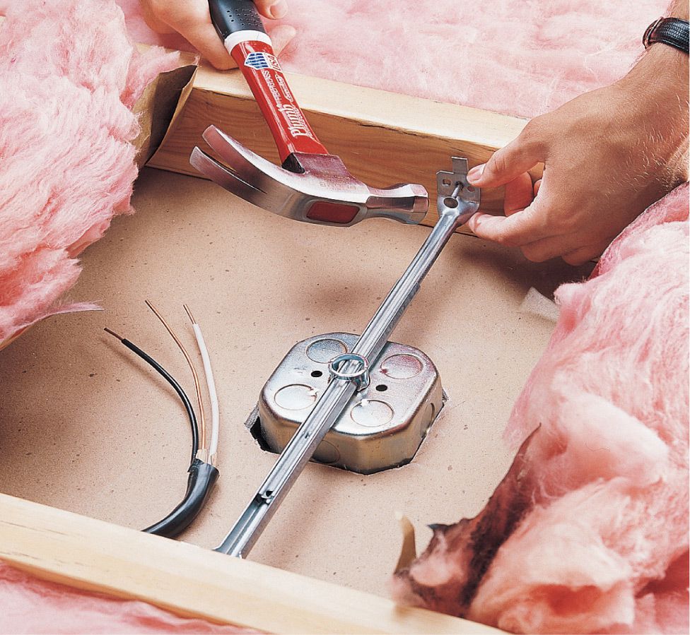
To position a light fixture between joists, attach an electrical box to an adjustable brace bar. Nail the ends of the brace bar to joists so the face of the box will be flush with the finished ceiling surface. Slide the box along the brace bar to the desired position, and then tighten the mounting screws. Use internal cable clamps when using a box with a brace bar. Note: For ceiling fans and heavy fixtures, use a metal box and a heavy-duty brace bar rated for heavy loads (inset photo).
![]() How to Install Boxes for Switches
How to Install Boxes for Switches
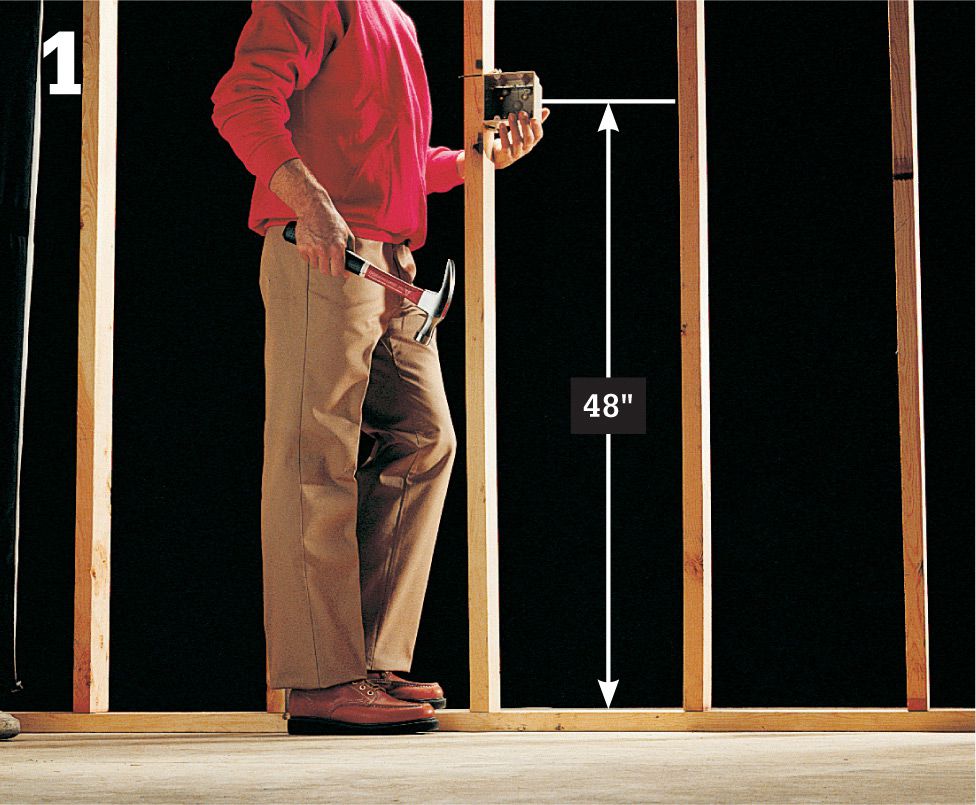
Install switch boxes at accessible locations, usually on the latch side of a door, with the center of the box 48" from the floor. The box for a thermostat is mounted at 48" to 60". Position each box against the side of a stud so the front face will be flush with the finished wall, and drive the mounting nails into the stud.
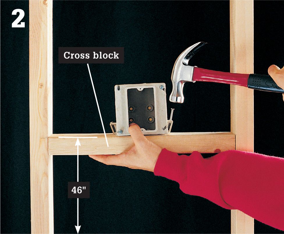
To install a switch box between studs, first install a cross block between studs, with the top edge 46" above the floor. Position the box on the cross block so the front face will be flush with the finished wall, and drive the mounting nails into the cross block.
![]() How to Locate Electrical Boxes
How to Locate Electrical Boxes
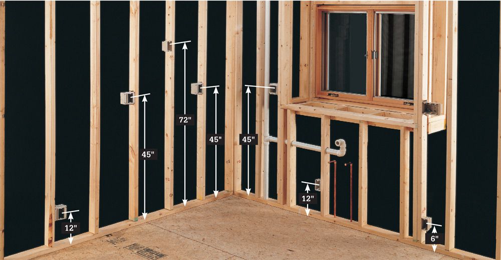
Heights of electrical boxes vary depending on use. In the kitchen shown here, boxes above the countertop are 45" above the floor, in the center of 18" backsplashes that extend from the countertop to the cabinets. All boxes for wall switches also are installed at this height. The center of the box for the microwave receptacle is 72" off the floor. The centers of the boxes for the range and food disposer receptacles are 12" off the floor, but the center of the box for the dishwasher receptacle is 6" off the floor.
![]() Typical Wallcovering Thickness
Typical Wallcovering Thickness
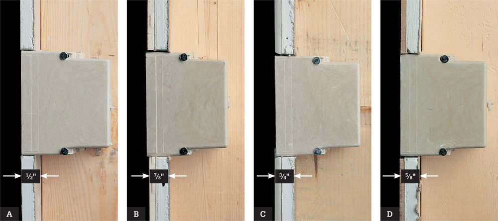
Consider the thickness of finished walls when mounting electrical boxes against framing members. Code requires that the front face of boxes be flush with the finished wall surface, so how you install boxes will vary depending on the type of wall finish that will be used. For example, if the walls will be finished with 1/2" wallboard (A), attach the boxes so the front faces extend 1/2" past the front of the framing members. With ceramic tile and wall board (B), extend the boxes 7/8" past the framing members. With 1/4" Corian® over wallboard (C), boxes should extend 3/4"; and with wallboard and laminate (D), boxes extend 5/8".
![]() Ceiling Boxes
Ceiling Boxes
Ceiling boxes for lights are generally round or octagonal in shape to fit typical lamp mounting plates. The easiest way to install one is by nailing the brace to open ceiling joists from above. If the ceiling is insulated, pull the insulation away from the box if the fixture you’re installing is not rated IC for insulation contact.
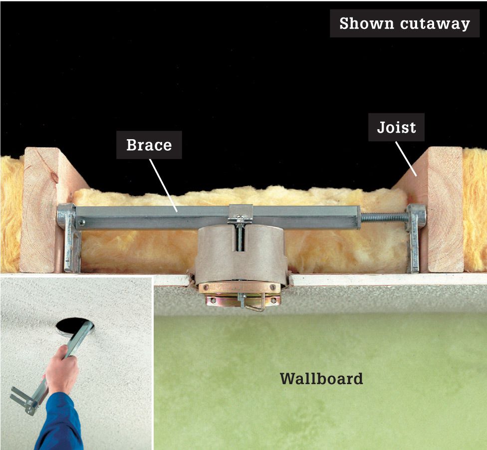
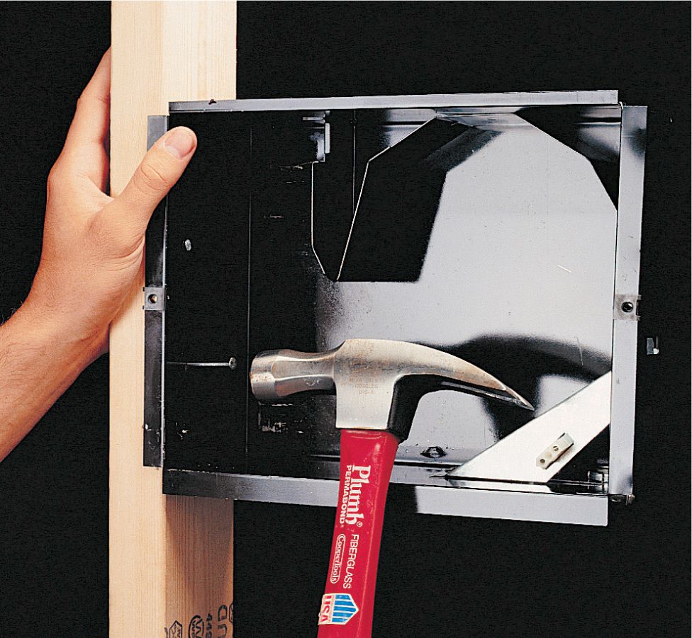
A heavy-duty brace is required for anchoring boxes that will support heavy chandeliers and ceiling fans. A remodeling brace such as the one seen here is designed to install through a small cutout in the ceiling (inset photo).
![]() How to Install a Junction Box
How to Install a Junction Box
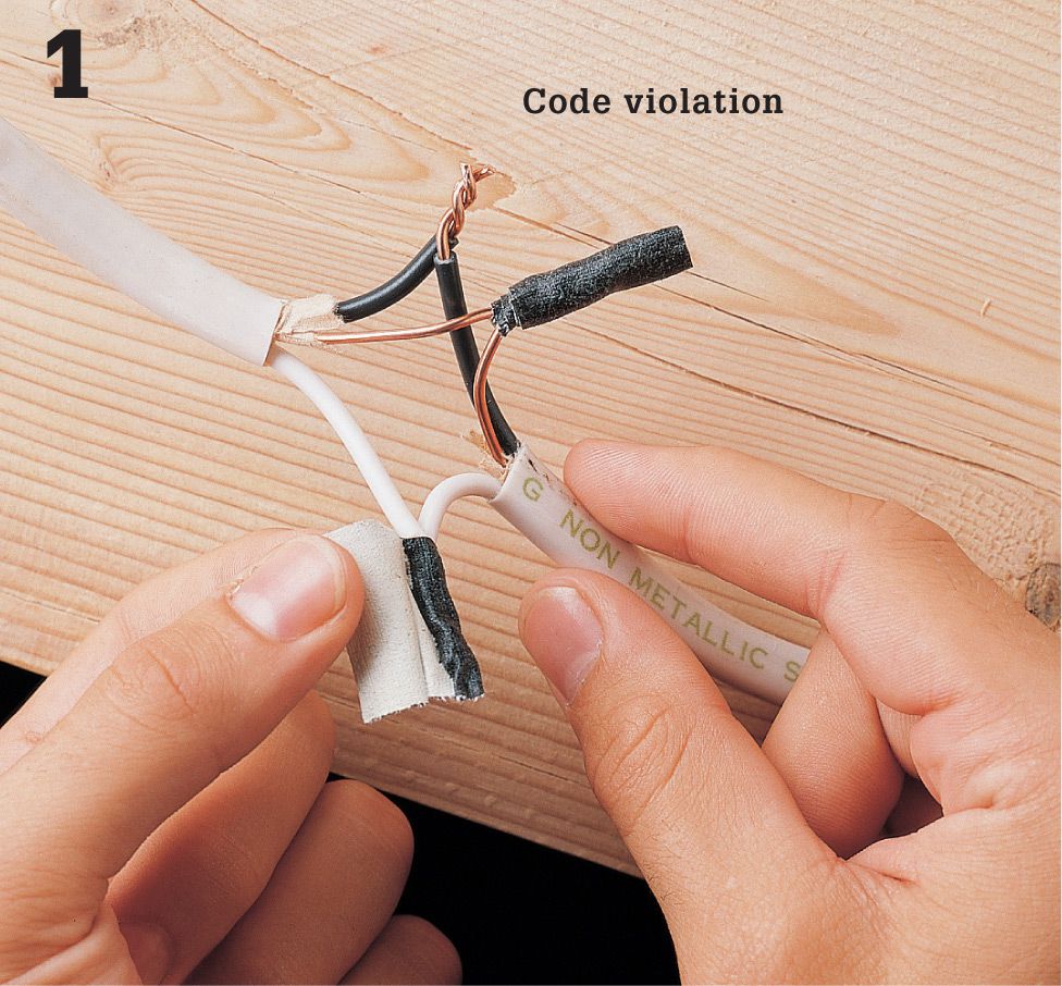
Turn off power to circuit wires at the main service panel. Test for power. Carefully remove any tape or wire connectors from the exposed slice. Disconnect the illegally spliced wires.
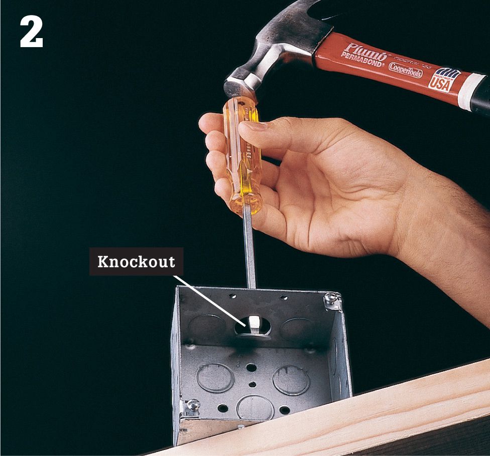
Open one knockout for each cable that will enter the box using a hammer and screwdriver. Any unopened knockouts should remain sealed.
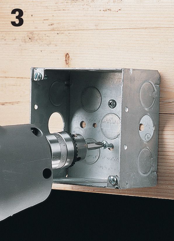
Anchor the electrical box to a wooden framing member using screws or nails.
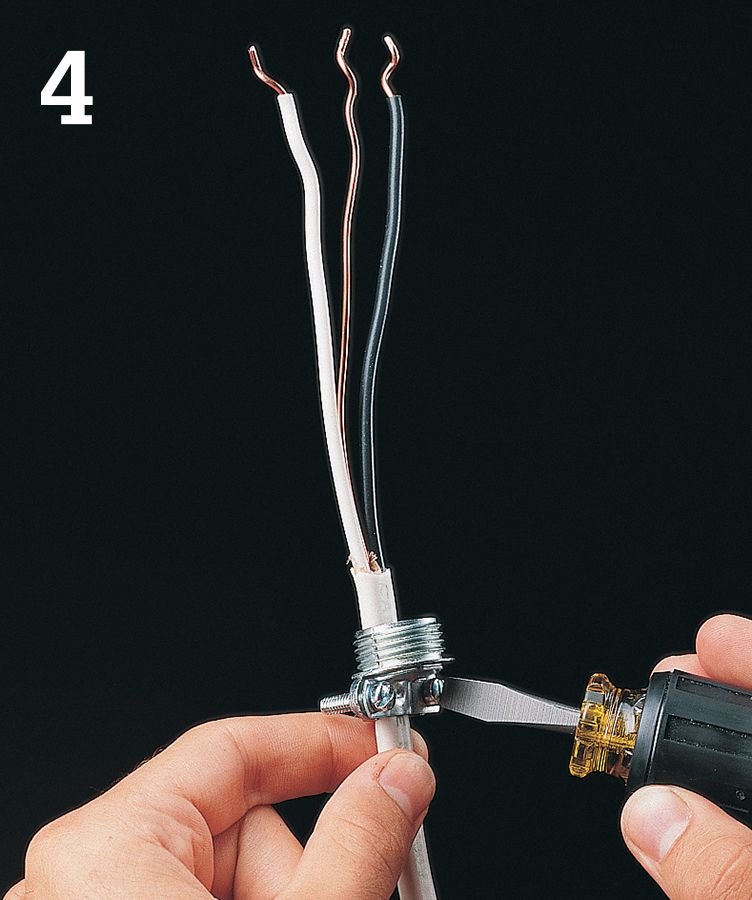
Thread each cable end through a cable clamp. Tighten the clamp with a screwdriver. See if there is any slack in the cables so you can gain a little extra cable to work with.
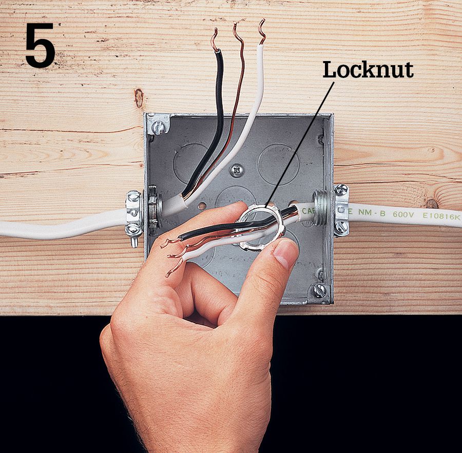
Insert the cables into the electrical box, and screw a locknut onto each cable clamp.
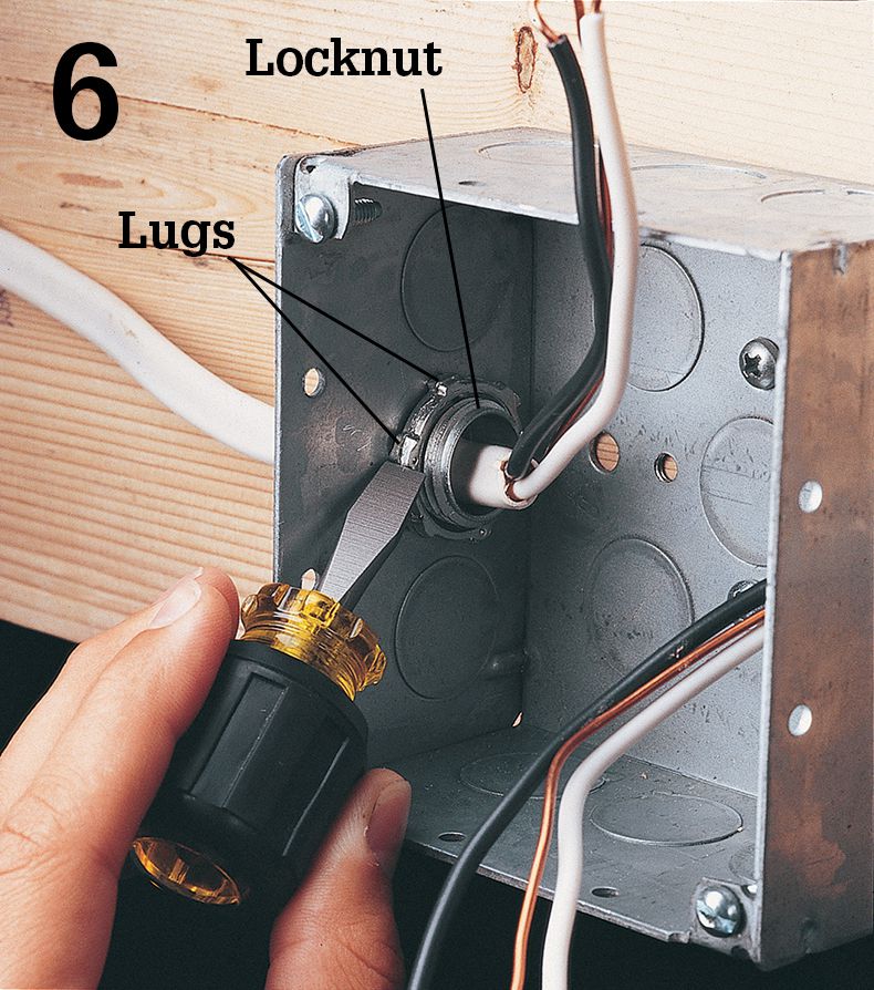
Tighten the locknuts by pushing against the lugs with the blade of a screwdriver.
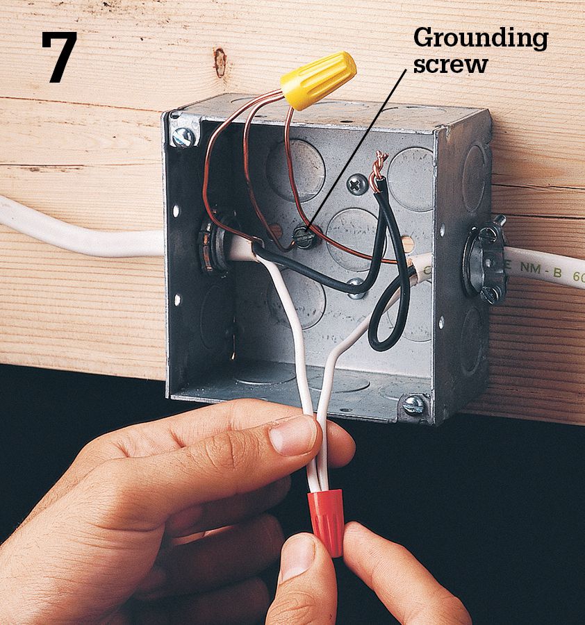
Use wire connectors to reconnect the wires. Pigtail the copper grounding wires to the green grounding screw in the back of the box.
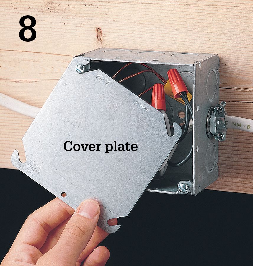
Carefully tuck the wires into the box, and attach the cover plate. Turn on the power to the circuit at the main service panel. Make sure the box remains accessible and is not concealed by finished walls or ceilings.
![]() Installing Pop-in Retrofit Boxes
Installing Pop-in Retrofit Boxes
Attaching an electrical box to a wall stud during new construction is relatively easy (pages 66 to 69). The task becomes complicated, however, when you’re working in finished walls during remodeling or repair. In most cases, it’s best to use an electronic stud finder, make a large cutout in the wall, and attach a new box directly to a framing member or bracing (and then replace and refinish the wall materials). But there are occasions when this isn’t possible or practical and you just need to retrofit an electrical box without making a large hole in the wall. You also may find that an older switch or receptacle box is too shallow to accommodate a new dimmer or GFCI safely. These situations call for a pop-in retrofit box (sometimes called an “old work” box).
A pop-in box typically has wings, tabs, or brackets that are drawn tight against the wall surface on the wall cavity side, holding the box in place. It can be made either of metal or plastic.
Tools & Materials ![]()
Screwdriver
Pencil
String
Electrical tape
Wallboard saw
Template (if provided)
Plastic or metal pop-in box
Eye protection
Pop-in boxes for remodeling come in a variety of styles. For walls, they include plastic retrofit boxes with flip-out wings (A), metal or plastic boxes with compression tabs or brackets (B), metal retrofit boxes with flip-out wings (C), and metal boxes with bendable brackets, also known as F-straps, (D). For ceilings, plastic fixture boxes with flip-out wings (E) are available.
![]() How to Replace an Electrical Box
How to Replace an Electrical Box
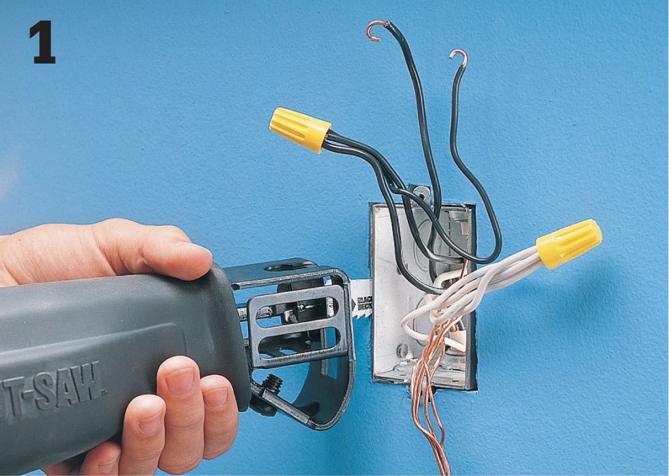
To install a dimmer switch or GFCI receptacle, you may have to replace an old, overcrowded box. Shut off power and remove the old switch or receptacle. Identify the location of nails holding the box to the framing member and cut the nails with a hacksaw or reciprocating saw with a metal blade inserted between the box and the stud.
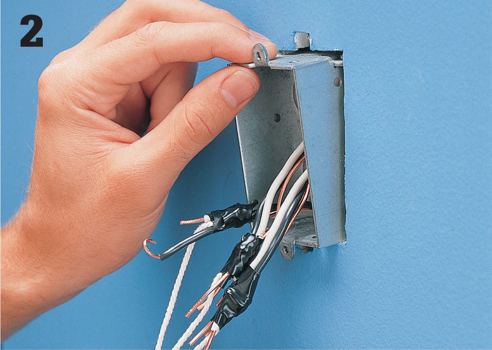
Bind the cable ends together and attach string in case they fall into the wall cavity when the old box is removed. Disconnect the cable clamps and slide the old box out. Install a new pop-in box (see next page).
![]() How to Install a Pop-in Box
How to Install a Pop-in Box
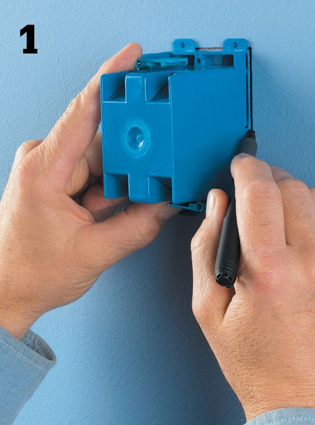
Use a template to trace a cutout for the box at the intended location. If no template is provided, press the pop-in box against the wall surface and trace its front edges (but not the tabs on the top and bottom).
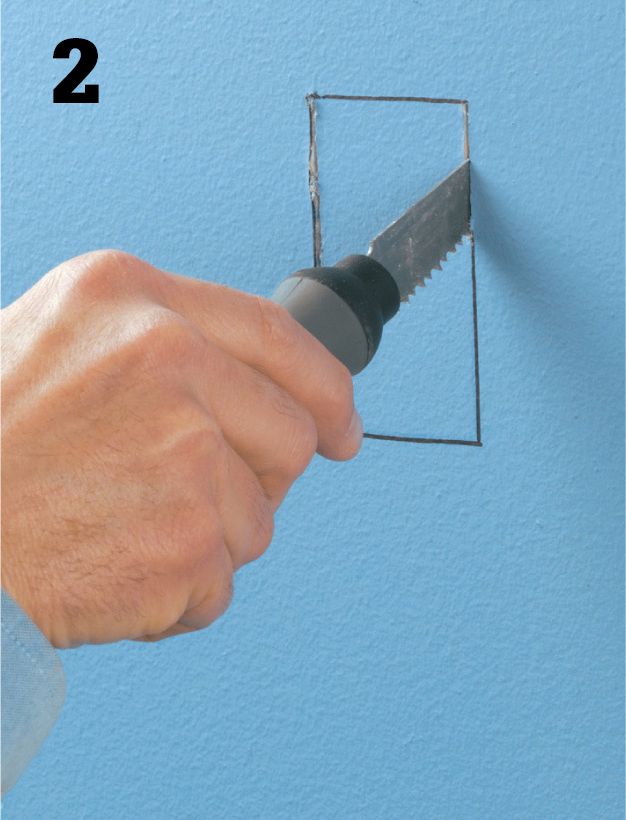
Puncture the wallboard with the tip of a wallboard saw or by drilling a small hole inside the lines, and make the cutout for the box.
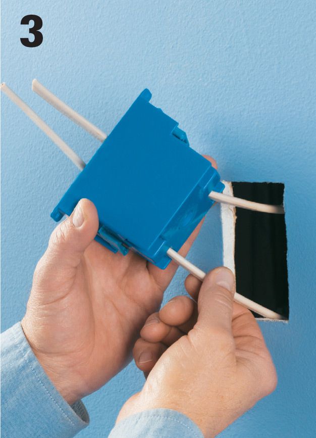
Pull NM cable through a knockout in the box (no cable clamp is required with a plastic box; just be sure not to break the pressure tab that holds the cable in place).
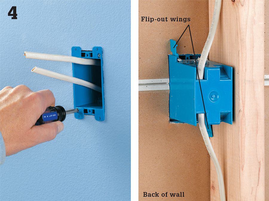
Insert the box into the cutout so the tabs are flush against the wall surface. Tighten the screws that cause the flip-out wings to pivot (right) until the box is held firmly in place. Connect the switch or receptacle that the box will house.
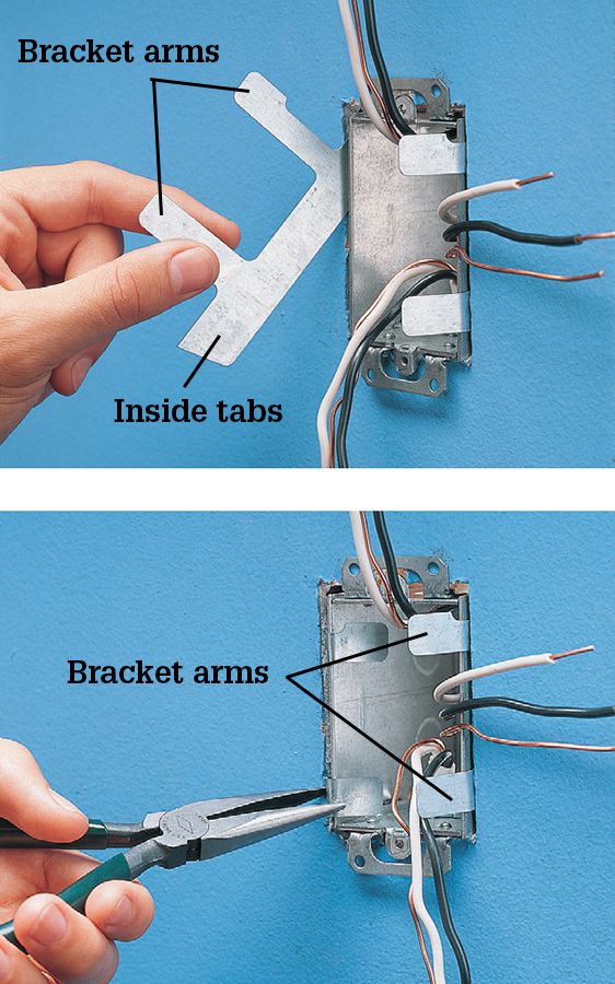
Variation: Feed cable into the new box and secure it in the opening after clamping the cables. With this pop-in box, bracket arms are inserted at the sides of the box (top) and then bent around the front edges to secure the box in the opening (bottom).
![]() Electrical Panels
Electrical Panels
Every home has a main panel that distributes electrical current to the individual circuits. The main panel may be found in the basement, garage, utility area, or on an exterior wall and can be identified by its metal casing. Before making any repair to your electrical system, you must shut off power to the correct circuit at the main panel or at the subpanel where the circuit begins. Every circuit in every panel should be labeled (see page 22) so circuits can be identified easily.
Panels vary in appearance, depending on the age of the system. Very old wiring may operate on 30-amp service that has only two circuits. New homes can have up to 400-amp service with 30 or more circuits. Find the size of the service by reading the amperage rating printed on the main fuse block or main circuit breakers.
Regardless of age, all panels have fuses or circuit breakers (see pages 78 to 81) that protect each circuit from overloads. In general, older service panels use fuses, while newer panels use circuit breakers.
In addition to the main panel, your electrical system may have one or more subpanels that protect some of the circuits in the home. A subpanel has its own circuit breakers or fuses.
The subpanel resembles the main service panel but is usually smaller. It may be located near the main panel, or it may be found near the areas served by the new circuits. Garages and basements that have been updated often have their own subpanels. If your home has subpanels, make sure that their circuits are indexed correctly.
When handling fuses or circuit breakers, make sure the area around the panel is dry. Never remove the protective cover on the panel. After turning off a circuit to make electrical repairs, remember to always test the circuit for power before touching any wires.
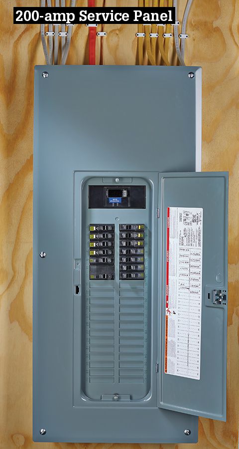
The main panel is the heart of your wiring system. As our demand for household energy has increased, the panels have also grown in capacity. Today, a 200-amp panel is often installed in new construction. Many homebuilders are installing dual 200-amp panels to deliver 400 amps to larger houses. A pair of 200-amp panels is much cheaper than one 400-amp panel.
A circuit breaker panel providing 100 amps or more of current is common in wiring systems installed during the 1960s and later. A circuit breaker panel is housed in a gray metal cabinet that contains two rows of individual circuit breakers. You can determine service size by reading the amperage rating of the main circuit breakers. In systems rated 200 amps and below, the main breaker is often located in the main panel, but it may be in a separate cabinet located elsewhere.
Larger new homes may have 300- or 400-amp service. These systems usually have two main circuit breakers in the main panel and at least one subpanel.
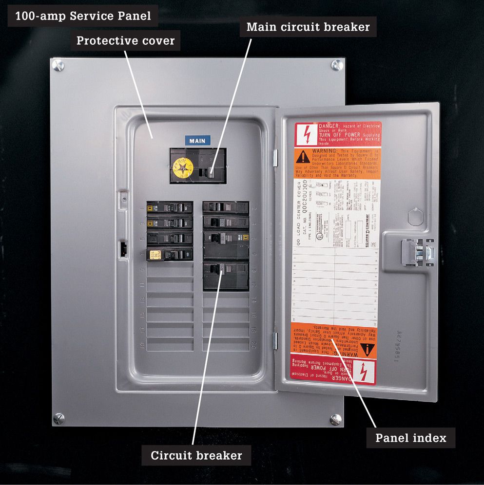
A 100-amp service panel is now the minimum standard for all new housing.
It is adequate for a medium-sized house with no more than three major electric appliances. However, larger houses with more electrical appliances require a service panel that provides 150 amps or more.
To shut off power to individual circuits in a circuit breaker panel, flip the lever on the appropriate circuit breaker to the OFF position. To shut off the power to the entire house, turn the main circuit breakers to the OFF position.
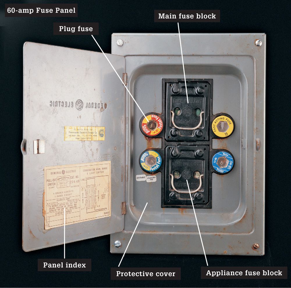
Some older homes may still have a 60-amp fuse panel. It usually is housed in a gray metal cabinet that contains four individual plug fuses, plus one or two pull-out fuse blocks that hold cartridge fuses. A 60-amp panel is considered undersized by current standards. The system should be upgraded for both convenience and safety. Insurance companies and mortgage lenders may require a complete electrical system upgrade before issuing a homeowner insurance policy or approving mortgage financing.
To shut off power to a circuit, carefully unscrew the plug fuse, touching only its insulated rim. To shut off power to the entire house, hold the handle of the main fuse block and pull sharply to remove it. Major appliance circuits are controlled with another cartridge fuse block. Shut off the appliance circuit by pulling out this fuse block.
![]() Circuit Breaker Panels
Circuit Breaker Panels
The circuit breaker panel is the electrical distribution center for your home. It divides the current into branch circuits that are carried throughout the house. Each branch circuit is protected by a circuit breaker that protects the wires from dangerous current overloads. When installing new circuits, the last step is to connect the wires to new circuit breakers at the panel. Follow basic safety procedures and always shut off the main circuit breaker and test for power before touching any parts inside the panel. Never touch the service wire lugs. If unsure of your own skills, hire an electrician to make the final circuit connections. (If you have an older electrical service with fuses instead of circuit breakers, always have an electrician make these final hookups.)
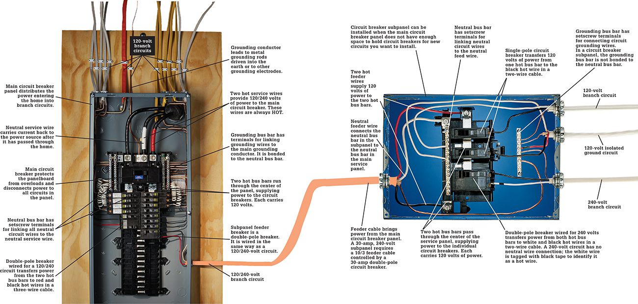
If a circuit breaker panel does not have enough open slots for new full-size circuit breakers, you may be able to install 1/2-height (slimline) circuit breakers. Otherwise, you will need to install a subpanel.
Before installing any new wiring, evaluate your electrical service to make sure it provides enough current to support both the existing wiring and any new circuits. If your service does not provide enough current, you will need to upgrade to a higher amp rating panel with enough extra breaker slots for the new circuits you want to install.
Safety Warning ![]()
Never touch any parts inside a circuit breaker panel until you have checked for power (see page 80). Circuit breaker panels differ in appearance, depending on the manufacturer. Never begin work in a circuit breaker panel until you understand its layout and can identify the parts.
![]() Fuses & Circuit Breakers
Fuses & Circuit Breakers
Fuses and circuit breakers are safety devices designed to protect the electrical system from short circuits and overloads. Fuses and circuit breakers are located in the main service panel and in subpanels.
Most service panels installed before 1965 rely on fuses to protect individual circuits. Screw-in plug fuses protect 120-volt circuits that power lights and receptacles. Cartridge fuses protect 240-volt appliance circuits and the main shutoff of the service panel.
Inside each fuse is a current-carrying metal alloy ribbon. If a circuit is overloaded, the metal ribbon melts and stops the current flow. A fuse must match the amperage rating of the circuit. Never replace a fuse with one that has a larger amperage rating.
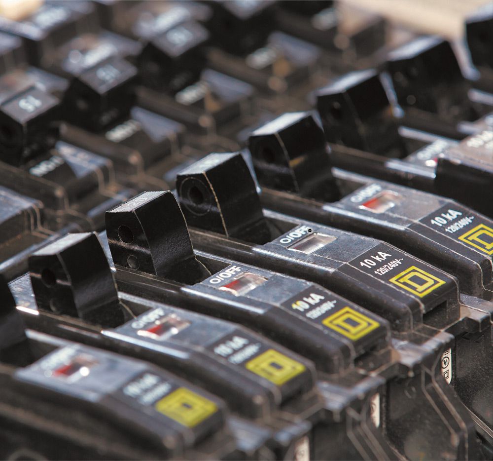
In most service panels installed after 1965, circuit breakers protect individual circuits. Single-pole circuit breakers protect 120-volt circuits, and double-pole circuit breakers protect 240-volt circuits. Amperage ratings for circuit breakers range from 15 to 100 amps.
Each circuit breaker has a permanent metal strip that heats up and bends when current passes through it. If a circuit is overloaded, the metal strip inside the breaker bends enough to “trip” the switch and stop the flow of power. Circuit breakers are listed to trip twice. After the second trip they weaken and tend to nuisance trip at lower currents. Replace breakers that have tripped more than twice—they may fail.
When a fuse blows or a circuit breaker trips, it is usually because there are too many light fixtures and plug-in appliances drawing power through the circuit. Move some of the plug-in appliances to another circuit, and then replace the fuse or reset the breaker. If the fuse blows or the breaker trips again immediately, there may be a short circuit in the system. Call a licensed electrician if you suspect a short circuit.
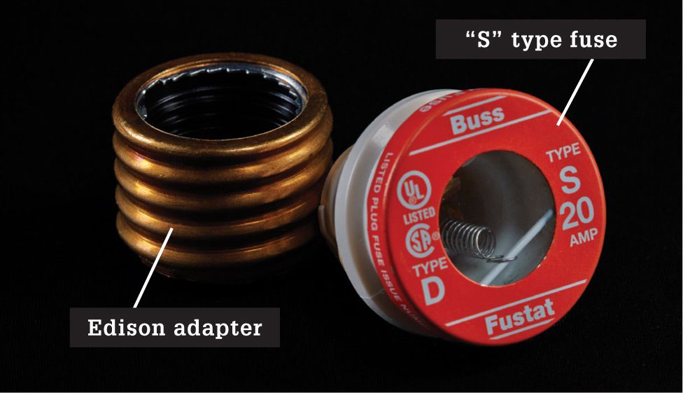
Old-style fuse boxes can accept modern “s” type fuses if you use an Edison adapter. Be sure to screw the fuse into the adapter first, and then screw the assembly into the socket.
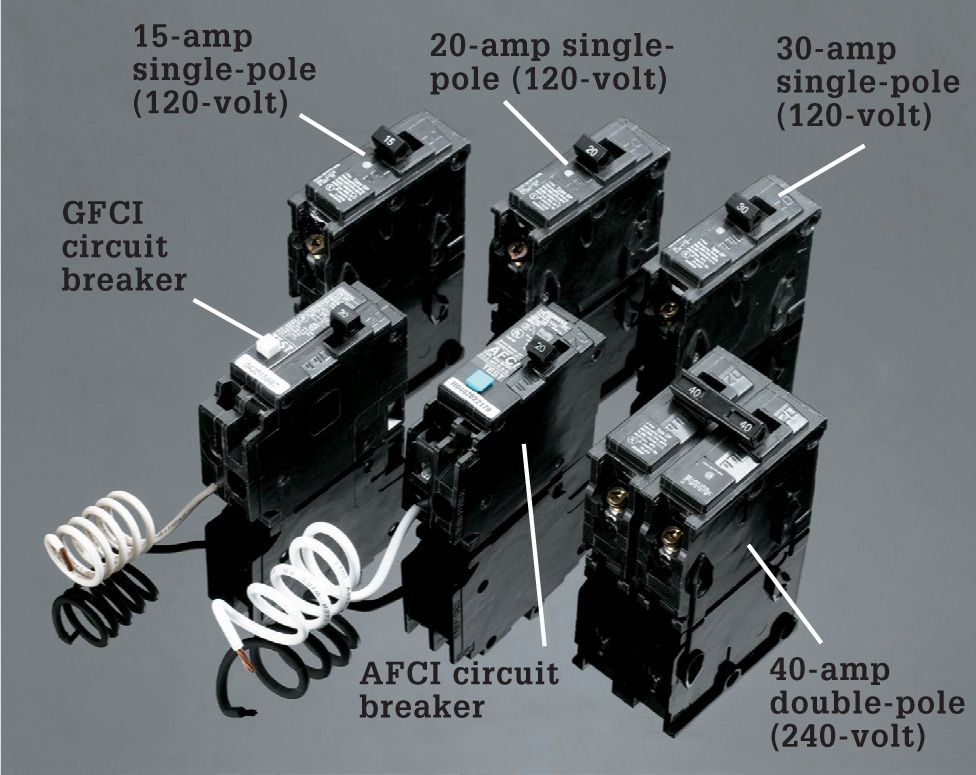
Circuit breakers are found in the majority of panels installed since the 1960s. Single-pole breakers control 120-volt circuits. Double-pole breakers rated for 20 to 60 amps control 240-volt circuits. Ground-fault circuit interrupter (GFCI) provides protection from shocks. Arc-fault circuit interrupter (AFCI) breakers provide protection from fire-causing arcs for the entire circuit.
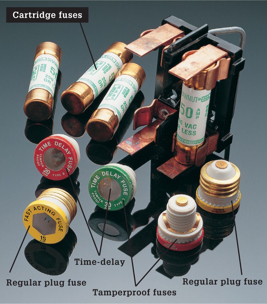
Fuses are used in older panels. Plug fuses usually control 120-volt circuits rated for 15, 20, or 30 amps. Tamper-proof plug fuses have threads that fit only matching sockets, making it impossible to install a wrong-sized fuse. Time-delay fuses absorb temporary heavy power loads without blowing. Cartridge fuses control 240-volt circuits and range from 30 to 100 amps.
![]() How to Identify & Replace a Blown Plug Fuse
How to Identify & Replace a Blown Plug Fuse
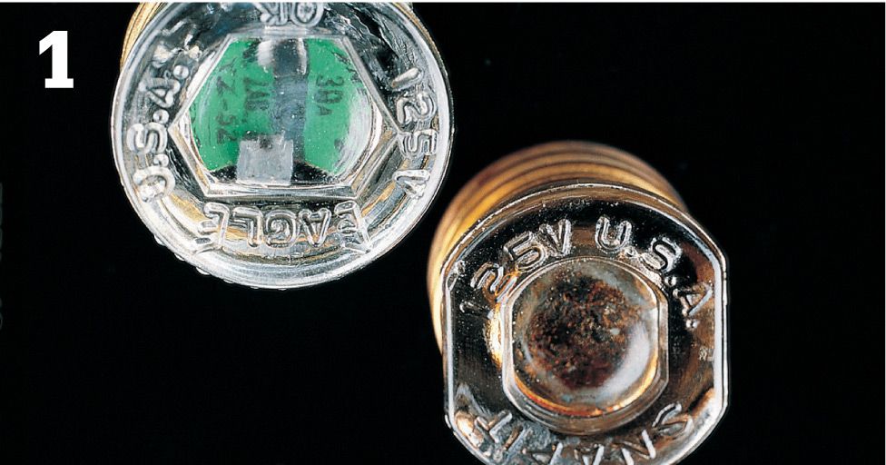
Locate the blown fuse at the panel. If the metal ribbon inside is cleanly melted (left), the circuit was overloaded. If window is discolored (right), there was a short circuit.
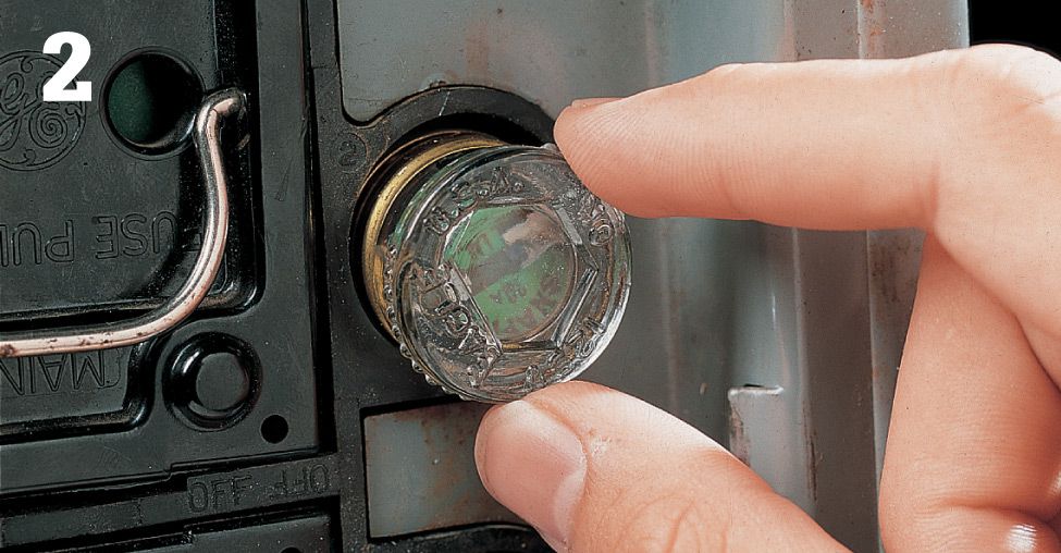
Unscrew the fuse, being careful to touch only the insulated rim of the fuse. Replace it with a fuse that has the same amperage rating.
![]() How to Remove, Test & Replace a Cartridge Fuse
How to Remove, Test & Replace a Cartridge Fuse
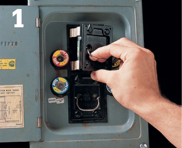
Remove cartridge fuses by gripping the handle of the fuse block and pulling sharply.
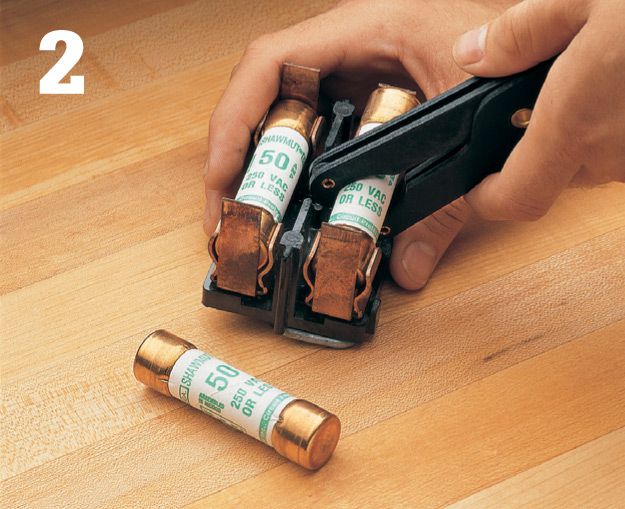
Remove the individual cartridge fuses from the block using a fuse puller.
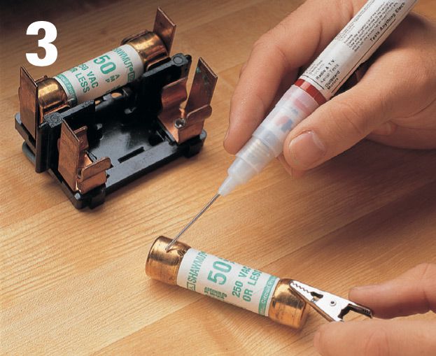
Test each fuse using a continuity tester. If the tester glows, the fuse is good. If not, install a new fuse with the same amperage rating.
![]() How to Reset a Circuit Breaker
How to Reset a Circuit Breaker
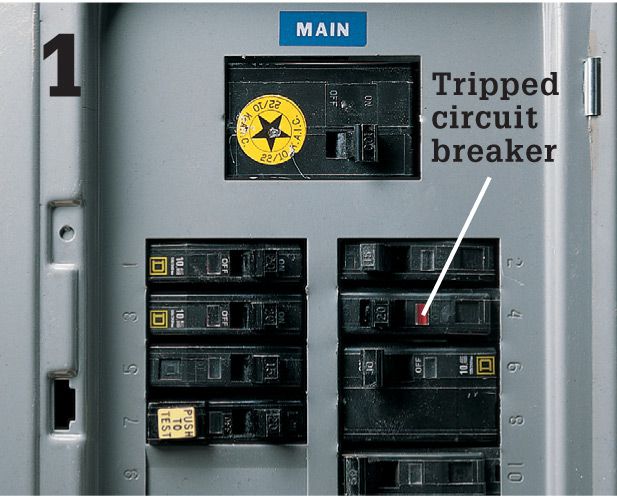
Open the service panel and locate the tripped breaker. The lever on the tripped breaker will be either in the OFF position or in a position between ON and OFF.
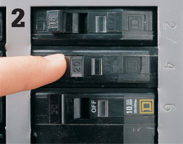
Reset the tripped circuit breaker by pressing the circuit breaker lever all the way to the OFF position and then pressing it to the ON position.
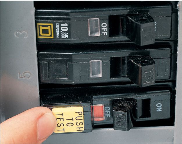
Test AFCI and GFCI circuit breakers by pushing the TEST button. The breaker should trip to the OFF position. If not, the breaker is faulty and must be replaced.
![]() Connecting Circuit Breakers
Connecting Circuit Breakers
The last step in a wiring project is connecting circuits at the breaker panel. After this is done, the work is ready for the final inspection.
Circuits are connected at the main panel, if it has enough open slots, or at a circuit breaker subpanel (see pages 74-77). When working at a subpanel, make sure the feeder breaker at the main panel has been turned off, and test for power (see photo, right) before touching any parts in the subpanel.
Make sure the circuit breaker amperage does not exceed the ampacity of the circuit wires you are connecting to it. Also be aware that circuit breaker styles and installation techniques vary according to manufacturer. Use breakers made by the panel manufacturer. You should install AFCI circuit breakers for most 15- and 20-amp, 120-volt circuits inside the home.
Tools & Materials ![]()
Screwdriver
Hammer
Pencil
Combination tool
Cable ripper
Circuit tester
Pliers
Cable clamps
Single- and double-pole AFCI circuit breakers
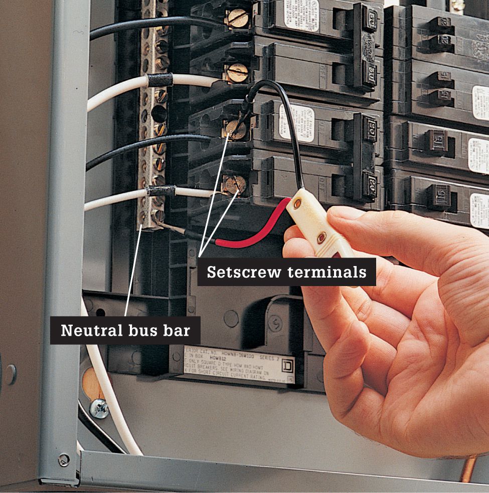
Test for current before touching any parts inside a circuit breaker panel. With the main breaker turned off but all other breakers turned on, touch one probe of a neon tester to the neutral bus bar, and touch the other probe to each setscrew on one of the double-pole breakers (not the main breaker). If the tester does not light for either setscrew, it is safe to work in the panel. Note: Touchless circuit testers are preferred in most situations where you are testing for current because they’re safer. But in some instances you’ll need a tester with individual probes to properly check for current.
![]() How to Connect Circuit Breakers
How to Connect Circuit Breakers
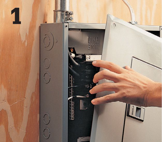
Shut off the main circuit breaker in the main circuit breaker panel (if you are working in a subpanel, shut off the feeder breaker in the main panel). Remove the panel cover plate, taking care not to touch the parts inside the panel. Test for power (photo, top).
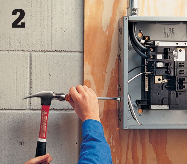
Open a knockout in the side of the circuit breaker panel using a screwdriver and hammer. Attach a cable clamp to the knockout.
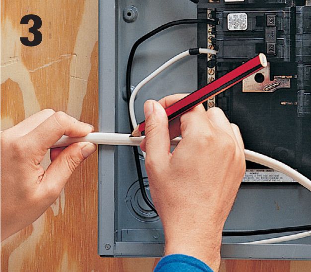
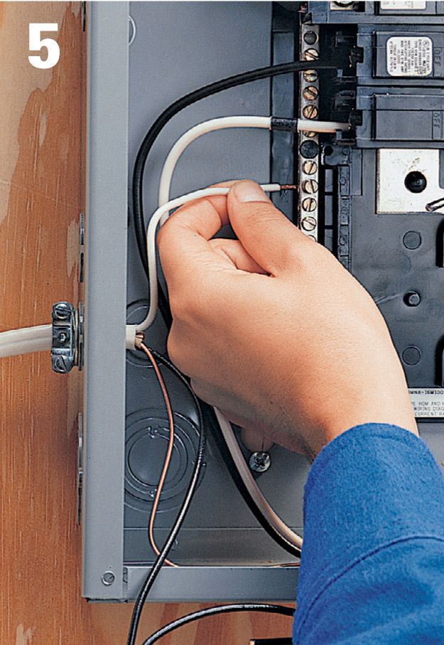
Hold the cable across the front of the panel near the knockout, and mark the sheathing about 1/2" inside the edge of the panel. Strip the cable from the marked line to the end using a cable ripper. (There should be 18" to 24" of excess cable.) Insert the cable through the clamp and into the service panel, and then tighten the clamp.
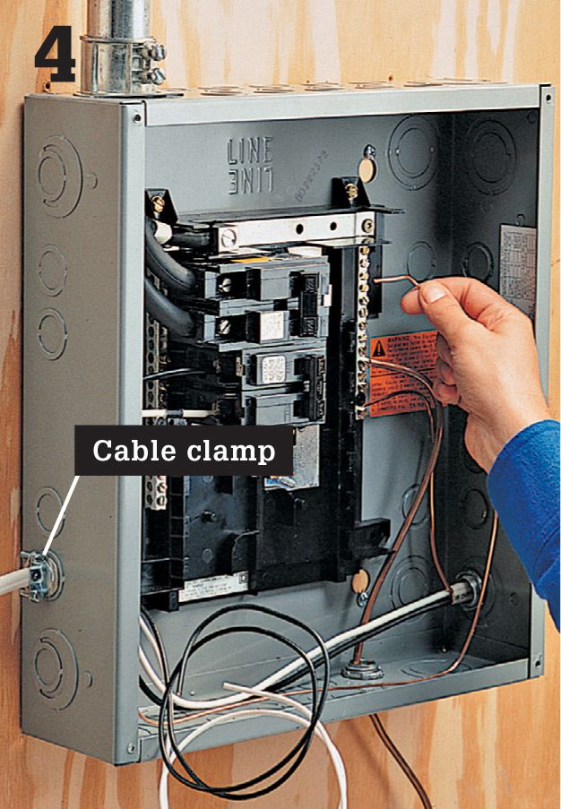
Bend the bare copper grounding wire around the inside edge of the panel to an open setscrew terminal on the grounding bus bar. Insert the wire into the opening on the bus bar, and tighten the setscrew. Fold excess wire around the inside edge of the panel.
For 120-volt circuits, bend the white circuit wire around the outside of the panel to an open setscrew terminal on the neutral bus bar. Clip away excess wire, and then strip 1/2" of insulation from the wire using a combination tool. Insert the wire into the terminal opening, and tighten the setscrew.
Strip 1/2" of insulation from the end of the black circuit wire. Insert the wire into the setscrew terminal on a new single-pole circuit breaker, and tighten the setscrew.

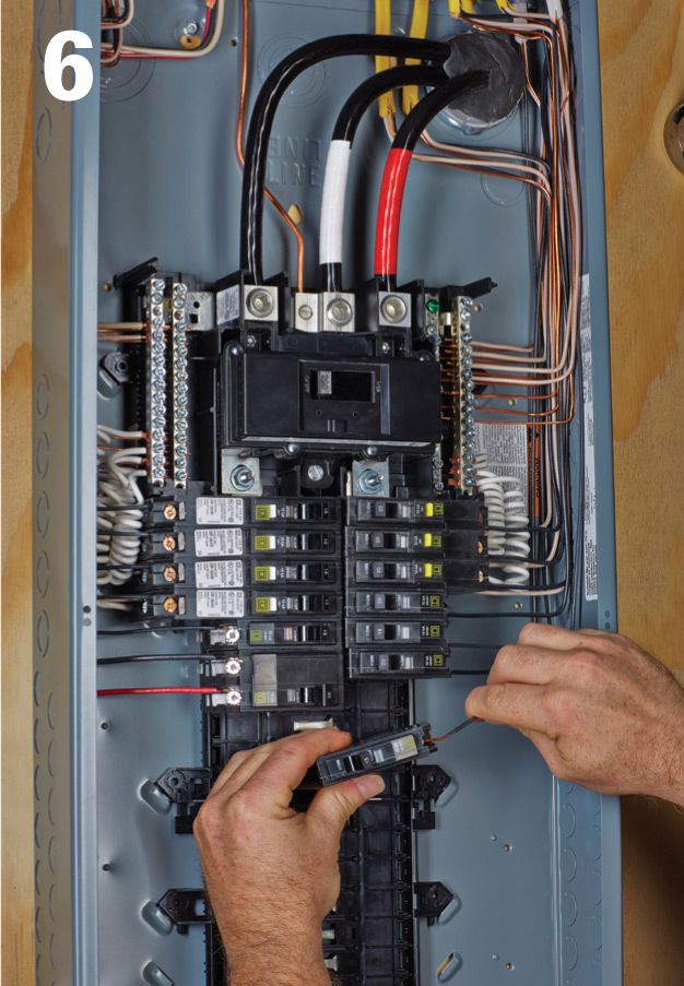
Slide one end of the circuit breaker onto the guide hook, and then press it firmly against the bus bar until it snaps into place. (Breaker installation may vary, depending on the manufacturer.) Fold excess black wire around the inside edge of the panel.
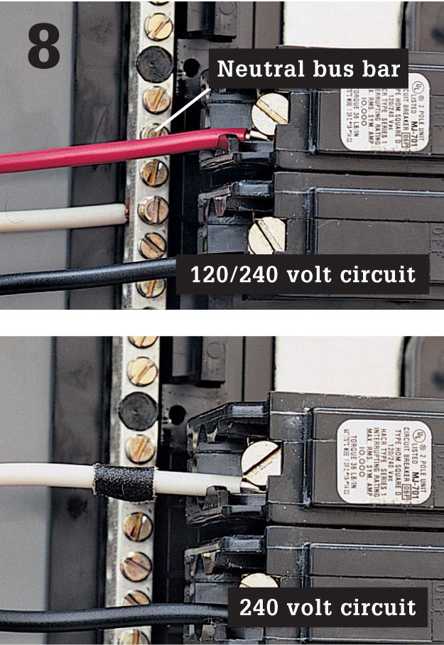
120/240-volt circuits (top): Connect red and black wires to the double-pole breaker. Connect white wire to the neutral bus bar, and the grounding wire to grounding bus bar. For 240-volt circuits (bottom), attach white and black wires to the double-pole breaker, tagging white wire with black tape. There is no neutral bus bar connection on this circuit.
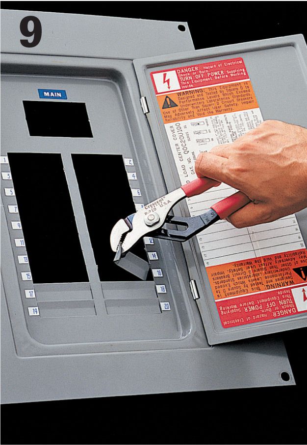
Remove the appropriate breaker tab on the panel cover plate to make room for the new circuit breaker. A single-pole breaker requires one tab, while a double-pole breaker requires two tabs. Reattach the cover plate, and label the new circuit on the panel index.