The Complete Guide to Wiring, Updated 6th Edition: Current with 2014-2017 Electrical Codes - Black & Decker, Cool Springs Press (2014)
APPENDIX: Common Mistakes
An electrical inspector visiting your home might identify a number of situations that are not up to code. These situations may not be immediate problems. In fact, it is possible that the wiring in your home has remained trouble free for many years.
Nevertheless, any wiring or device that is not up to code carries the potential for problems, often at risk to your home and your family. In addition, you may have trouble selling your home if it is not wired according to accepted methods.
Most local electrical codes are based on the National Electrical Code (NEC), a book updated and published every three years by the National Fire Protection Agency. This code book contains rules and regulations for the proper installation of electrical wiring and devices. Most public libraries carry reference copies of the NEC.
All electrical inspectors are required to be well versed in the NEC. Their job is to know the NEC regulations and to make sure these rules are followed in order to prevent fires and ensure safety. If you have questions regarding your home wiring system, your local inspector will be happy to answer them.
While a book cannot possibly identify all potential wiring problems in your house, we have identified some of the most common wiring defects here and will show you how to correct them. When working on home wiring repair or replacement projects, refer to this section to help identify any conditions that may be hazardous.
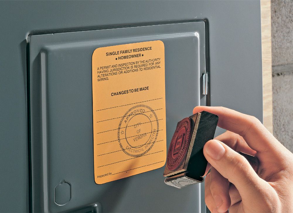
Electrical inspectors are on the lookout for common mistakes. The following pages detail problems to avoid so you will pass inspection on the first try.
![]() Service Panel Inspection
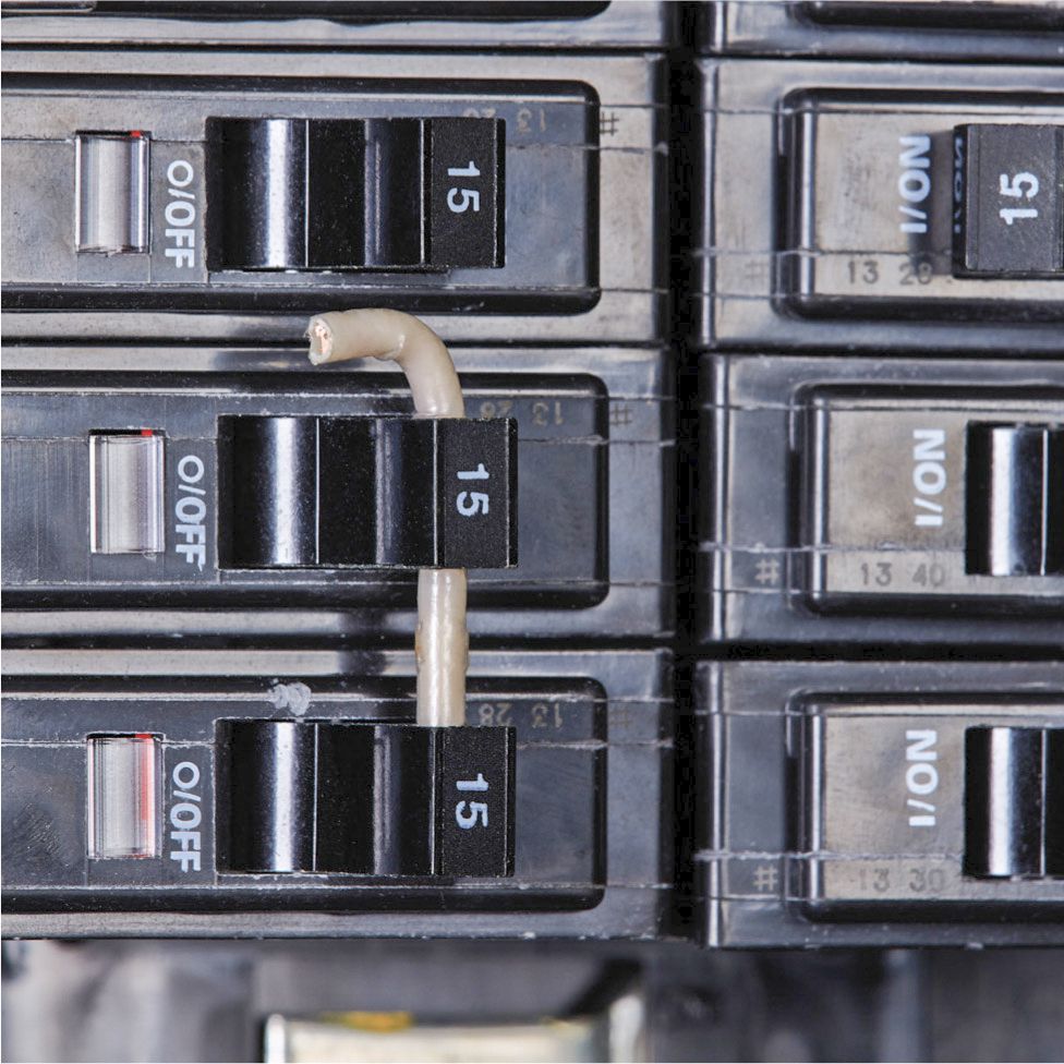
Service Panel Inspection
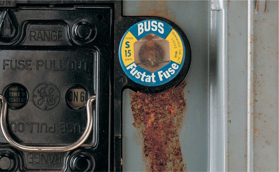
Problem: Rust stains are found inside the main service panel. This problem occurs because water seeps into the service head outside the house and drips down into the service panel.
Solution: Have an electrician examine the service mast, weather head, service entrance cables, and the main panel. If the panel or service wires have been damaged, new electrical service must be installed.
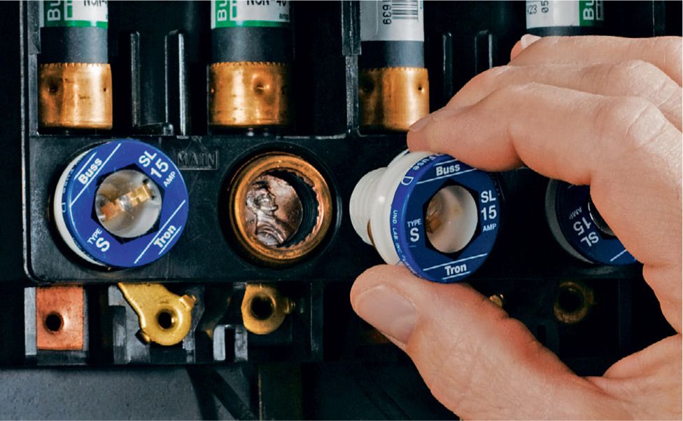
Problem: This problem is actually a very old and very dangerous solution. A penny or a knockout behind a fuse effectively bypasses the fuse, preventing an overloaded circuit from blowing the fuse. This is very dangerous and can lead to overheated wiring.
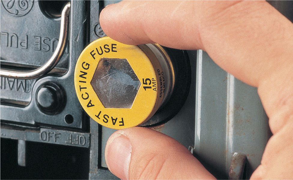
Solution: Remove the penny and replace the fuse. Have a licensed electrician examine the panel and circuit wiring. If the fuse has been bypassed for years, wiring may be dangerously compromised, and the circuit may need to be replaced. In addition, if you have the old Edison fuse socket, replace it with a new S-type fuse socket. This eliminates the related problem of installing the wrong-size fuse in the panel.
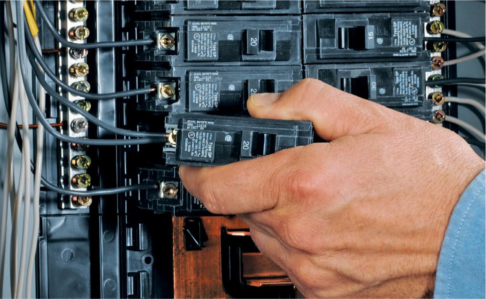
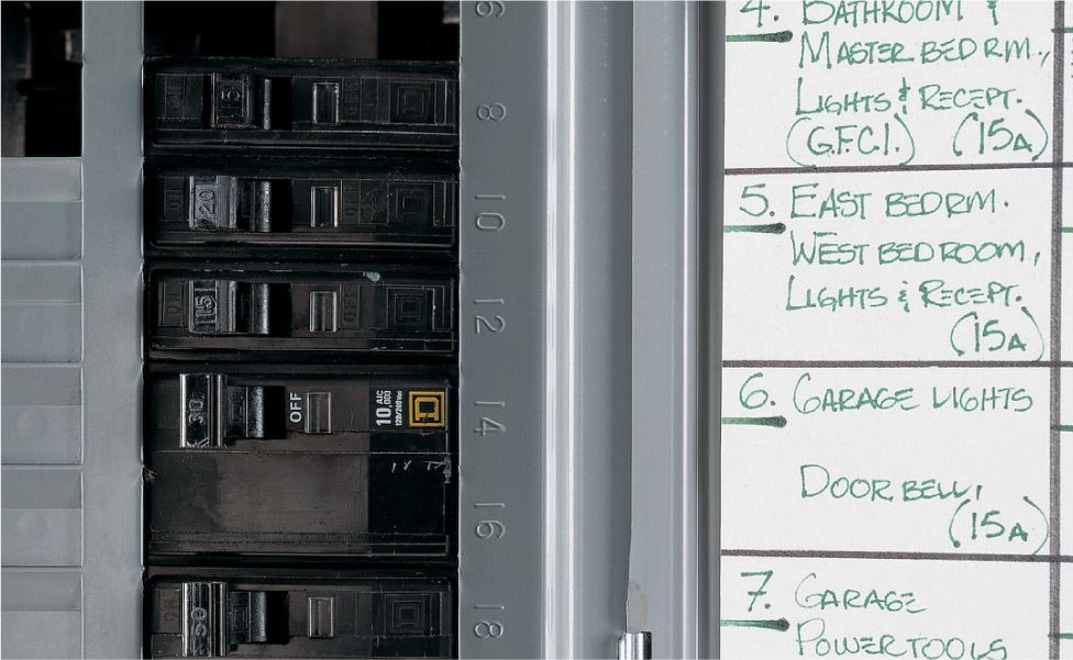
Problem: Two wires connected to one single-pole breaker is a sign of an overcrowded panel and also a dangerous code violation unless the breaker is approved for such a connection.
Solution: If there is room in the panel, install a separate breaker for the extra wire. If the panel is overcrowded, have an electrician upgrade the panel or install a subpanel.
![]() Other Common Panel Problems
Other Common Panel Problems
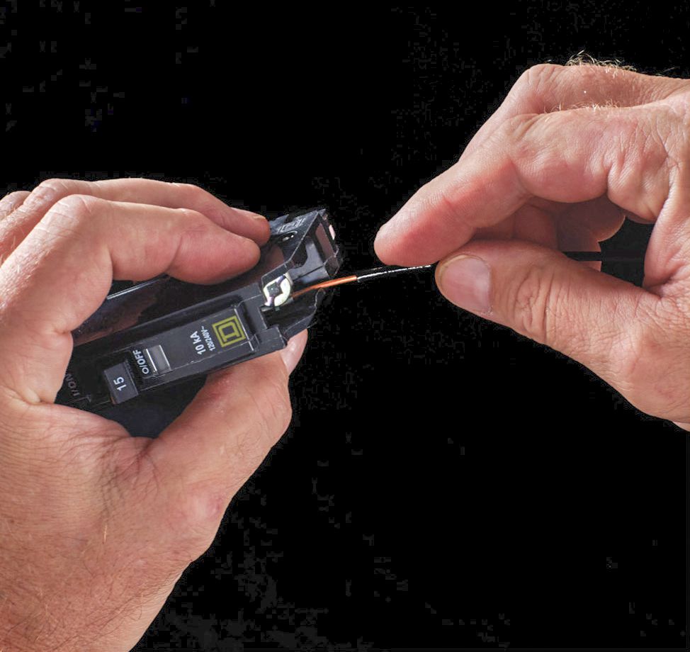
Problem: Too much bare wire exposed at the breaker connection. This presents a short-circuit hazard. Solution: With power off, trim the feed wire so no more than 1/2” of bare wire is exposed, and then reconnect.
Problem: There is no handle tie (or there is an improper handle tie) on breaker pair controlling a 240-volt circuit. Solution: Install a handle tie approved by the circuit breaker manufacturer.
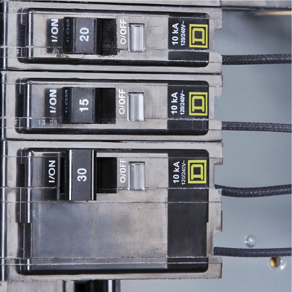
Problem: Conductor too small for breaker size. The #14 copper wires seen here are rated for 15 amp circuits. The 30-amp breaker allows too much current in the wires and could cause a fire. Solution: Replace the wires with wires approved for the circuit breaker size.
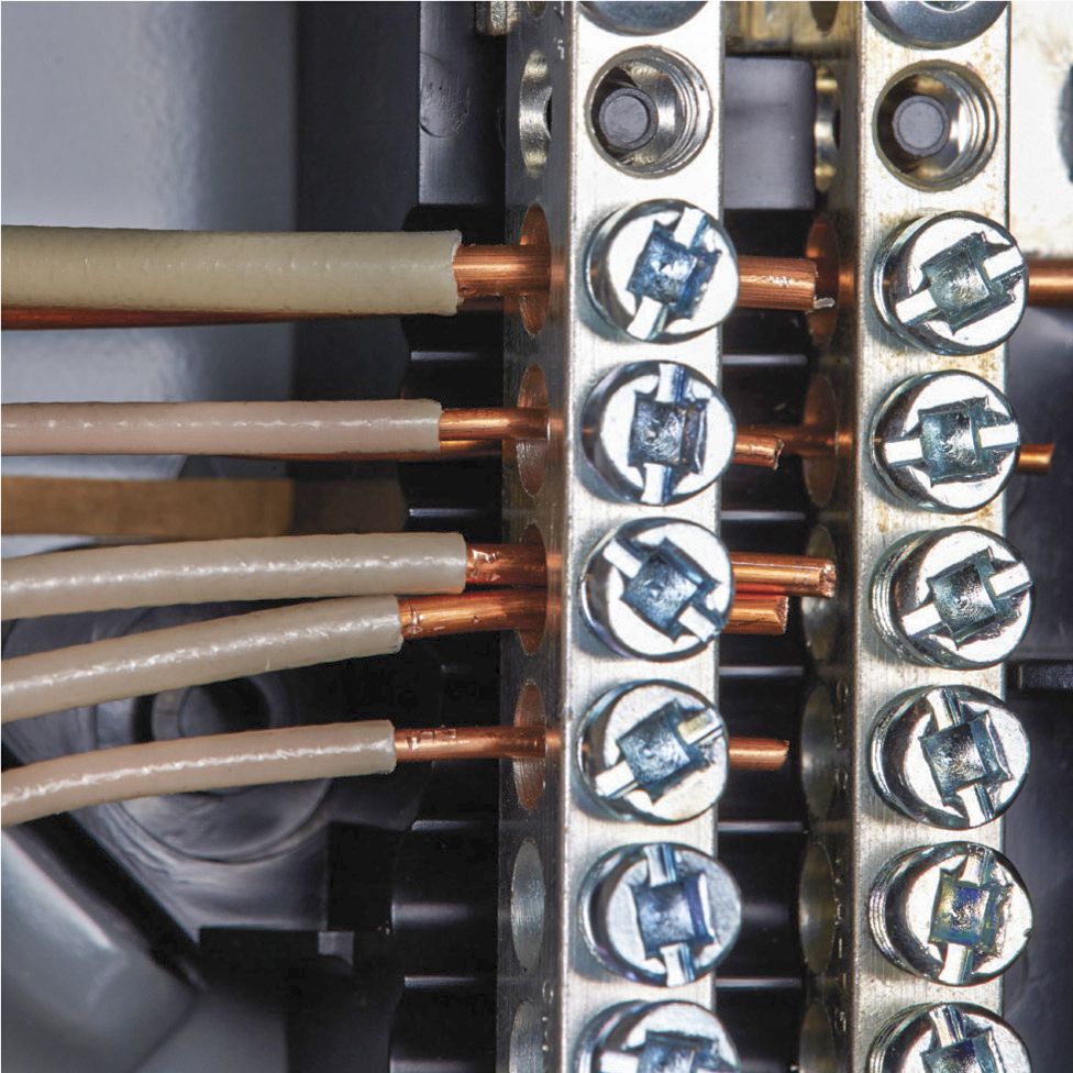
Problem: There is more than one neutral in a buss terminal. Sharing slots is fine for grounding wires, but each neutral wire should have its own terminal. Solution: Remove one of the wires and find an open terminal for it.
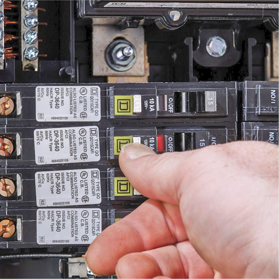
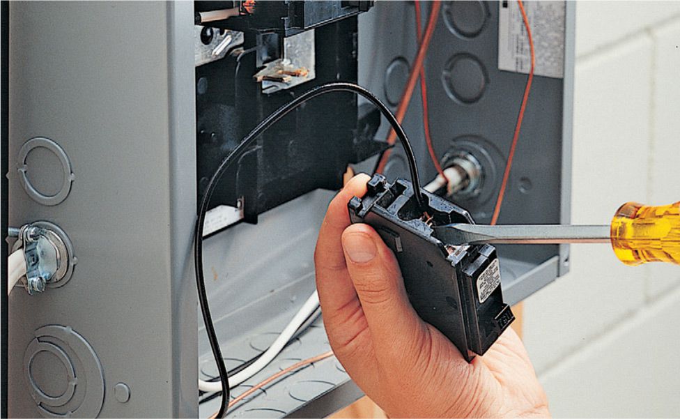
Problem: Arc-fault protection (AFCI) circuit breakers may fail, especially if they are tripped with some frequency. Solution: Test each breaker as recommended by the manufacturer by depressing the “Test” button. If the breaker is functioning correctly it will trip when the button is pushed.
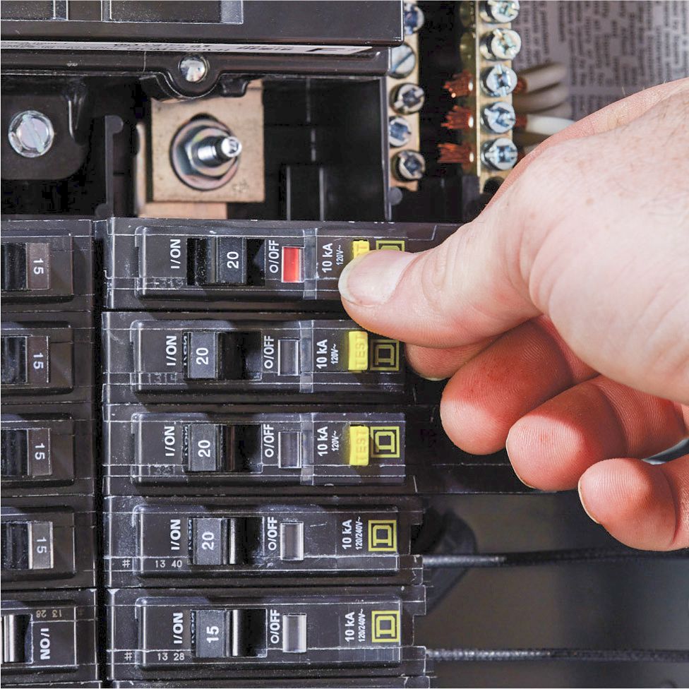
Problem: GFCI circuit breakers may fail, especially if they are tripped with some frequency. Solution: Test each breaker as recommended by the manufacturer by depressing the “Test” button. If the breaker is functioning correctly it will trip when the button is pushed.
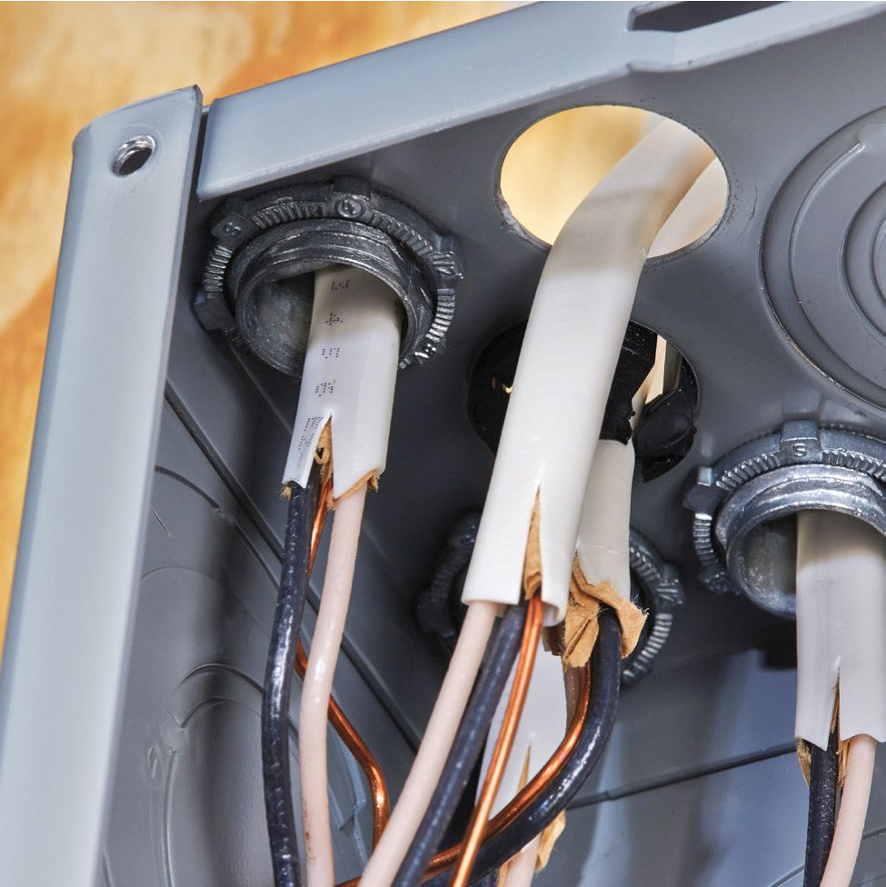
Problem: There is a missing cable clamp at panel box. All NM cable entering a service panel (or any other box) needs protection from sharp edges that can cut sheathing. Solution: Disconnect the cable in the box, and retract and reinstall it with cable clamps.
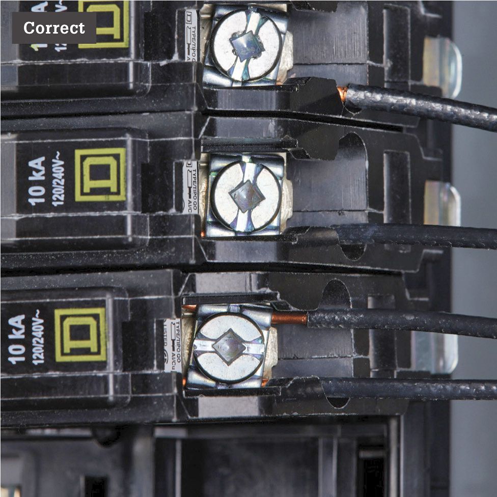
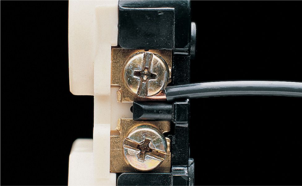
Problem: The shared hot terminal on the breaker is not wired correctly. The example above is correct: the conductors should be positioned on opposite sides of the terminal and held securely in the separate grooves by the terminal screw.
![]() Common Cable Problems
Common Cable Problems
Problem: Cable running across joists or studs is attached to the edge of framing members. Electrical codes forbid this type of installation in exposed areas such as unfinished basements and crawl spaces.
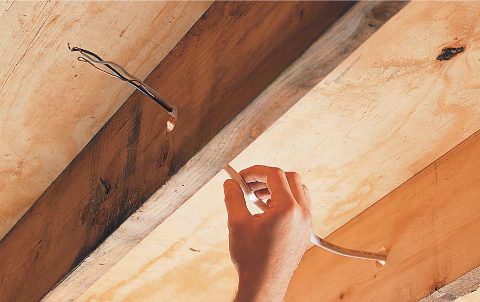
Solution: Protect cable by drilling holes in framing members at least 2" from exposed edges and threading the cable through the holes.
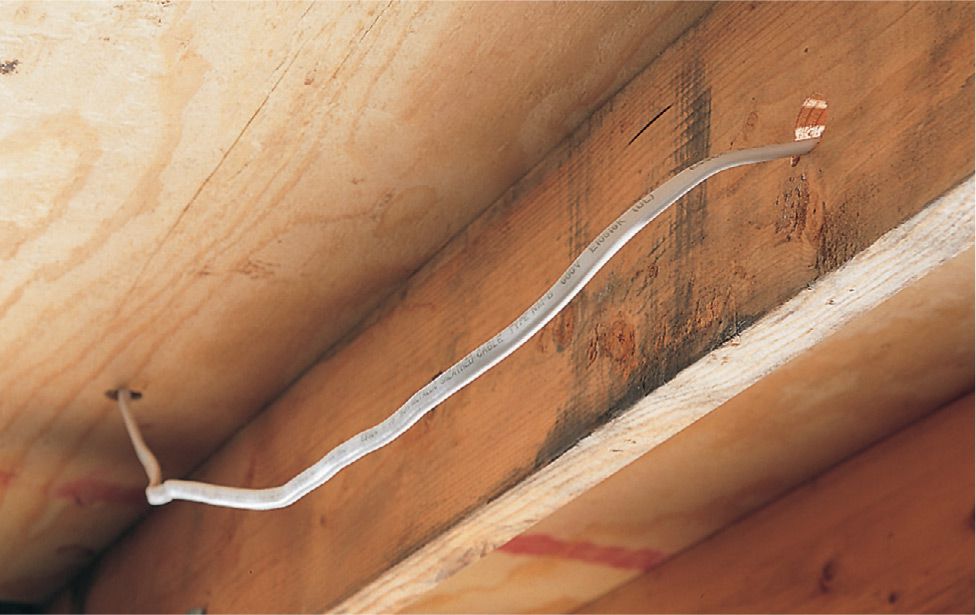
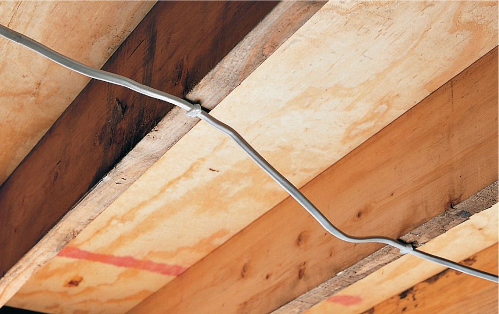
Problem: Cable running along joists or studs hangs loosely. Loose cables can be pulled accidentally, causing damage to wires.
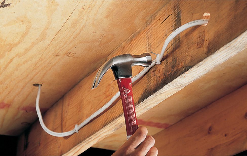
Solution: Anchor the cable to the side of the framing members at least 1 1/4" from the edge using plastic staples. NM cable should be stapled every 4 1/2 ft. and within 8" of each electrical box.
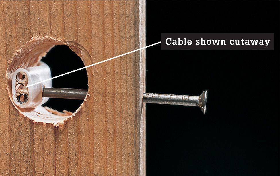
Problem: Cable threaded through studs or joists lies close to the edge of the framing members. NM cable (shown cutaway) can be damaged easily if nails or screws are driven into the framing members during remodeling projects.
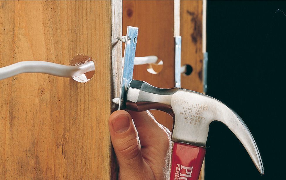
Solution: Install metal nail guards to protect cable from damage. Nail guards are available at hardware stores and home centers.
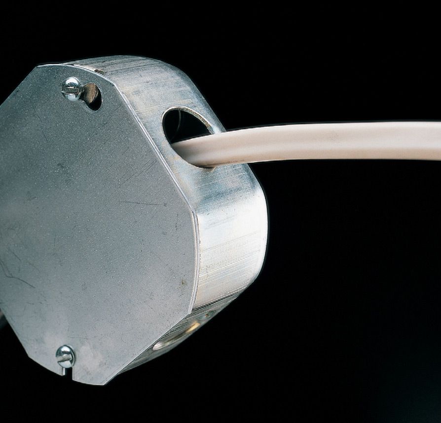
Problem: Unclamped cable enters a metal electrical box. Edges of the knockout can rub against the cable sheathing and damage the wires. Note: With smaller plastic boxes, clamps are not required if cables are anchored to framing members within 8" of the box.
Solution: Anchor the cable to the electrical box with a cable clamp. Several types of cable clamps are available at hardware stores and home centers.
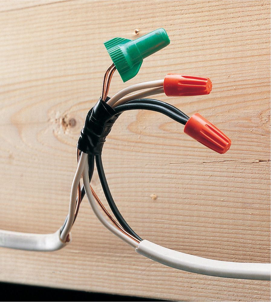
Problem: Cables are spliced outside an electrical box. Exposed splices can spark and create a risk of shock or fire.
Solution: Bring installation up to code by enclosing the splice inside a metal or plastic electrical box. Make sure the box is large enough to accommodate the number of wires it contains.
![]() Checking Wire Connections
Checking Wire Connections
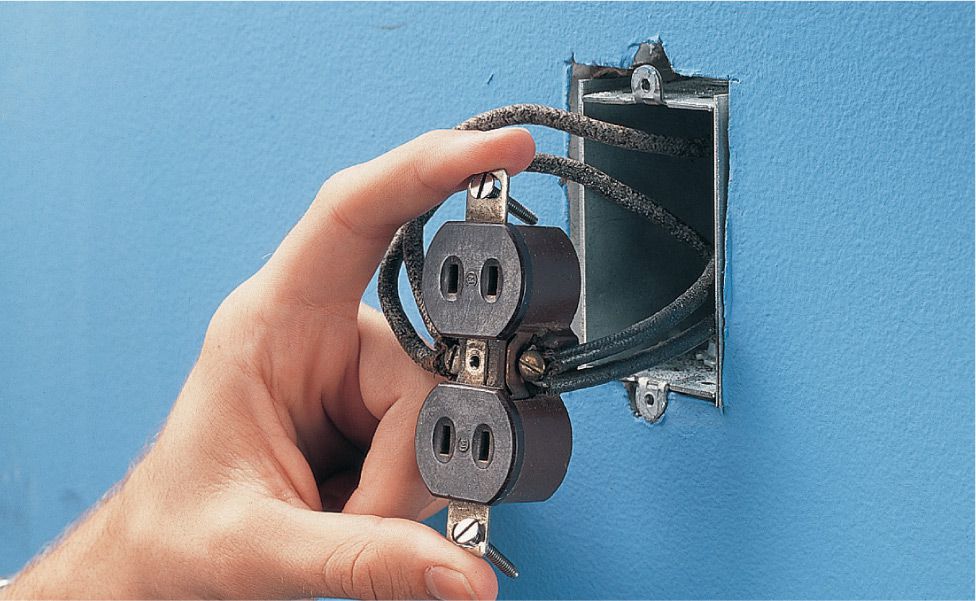
Problem: Two or more wires are attached to a single-screw terminal. This type of connection is seen in older wiring but is now prohibited by the NEC.
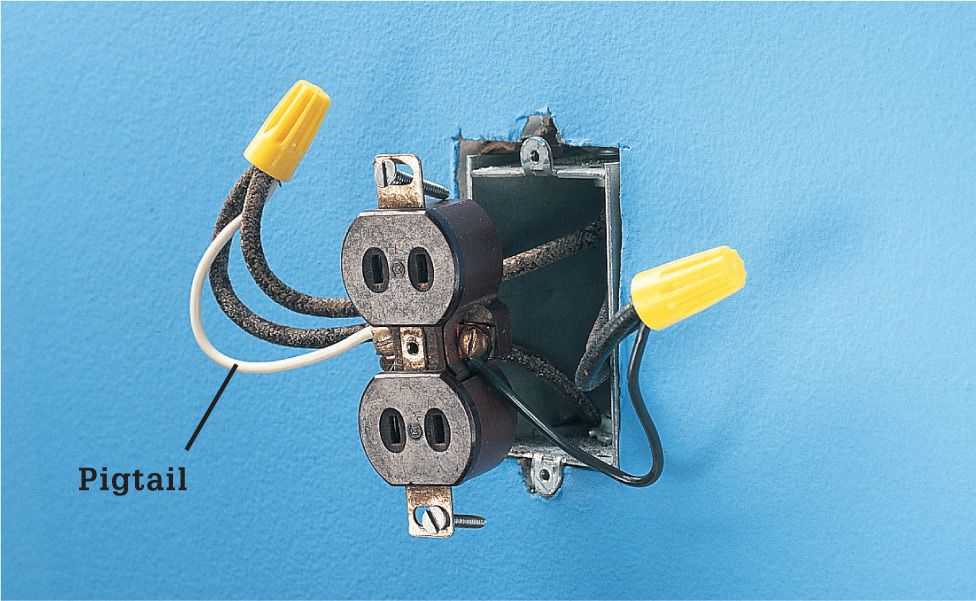
Solution: Disconnect the wires from the screw terminal, and then join them to a short length of wire (called a pigtail) using a wire connector. Connect the other end of the pigtail to the screw terminal.
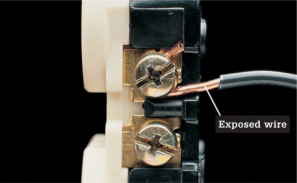
Problem: Bare wire extends past a screw terminal. Exposed wire can cause a short circuit if it touches the metal box or another circuit wire.
Solution: Clip the wire and reconnect it to the screw terminal. In a proper connection, the bare wire wraps completely around the screw terminal, and the plastic insulation just touches the screw head.
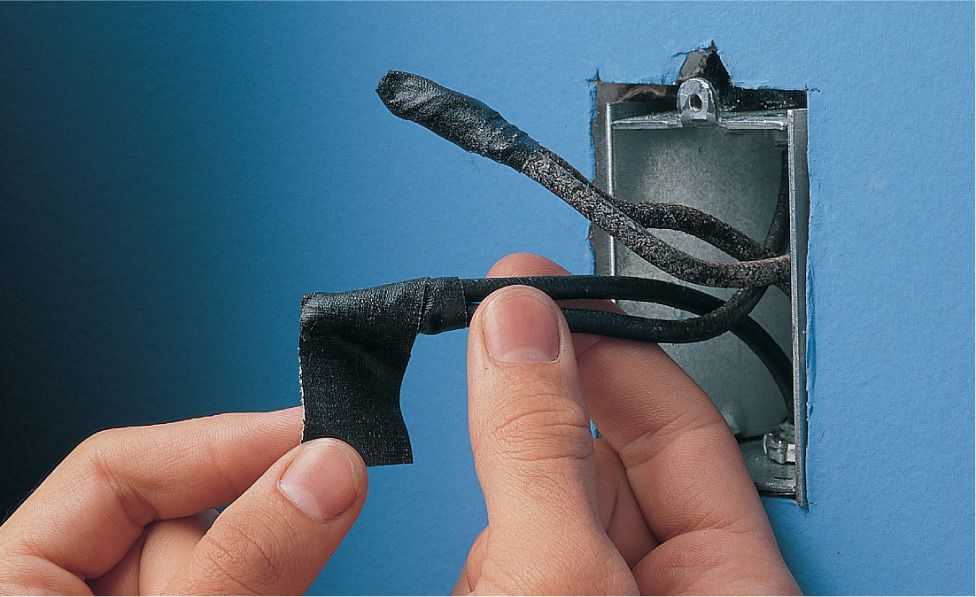
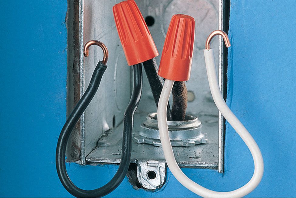
Problem: Wires are connected with electrical tape. Electrical tape was used frequently in older installations, but it can deteriorate over time, leaving bare wires exposed inside the electrical box.
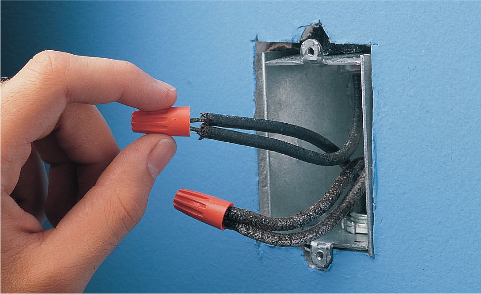
Solution: Replace electrical tape with wire connectors. You may need to clip away a small portion of the wire so the bare end will be covered completely by the connector.
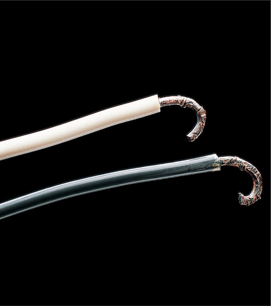
Problem: Nicks and scratches in bare wires interfere with the flow of current. This can cause the wires to overheat.
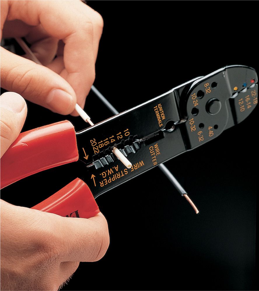
Solution: Clip away damaged portion of wire, restrip about 3/4" of insulation, and reconnect the wire to the screw terminal.
![]() Electrical Box Inspection
Electrical Box Inspection
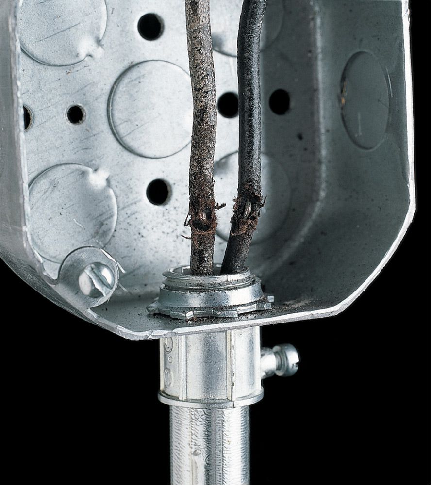
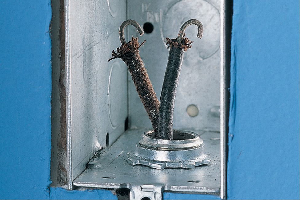
Problem: Insulation on wires is cracked or damaged. If damaged insulation exposes bare wire, a short circuit can occur, posing a shock hazard and fire risk.
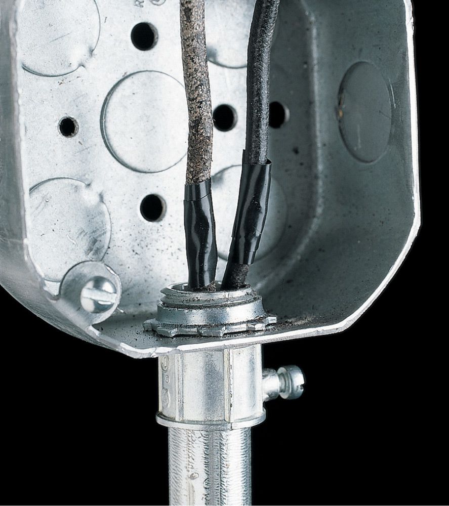
Solution: Wrap damaged insulation temporarily with plastic electrical tape. Damaged circuit wires should be replaced by an electrician.
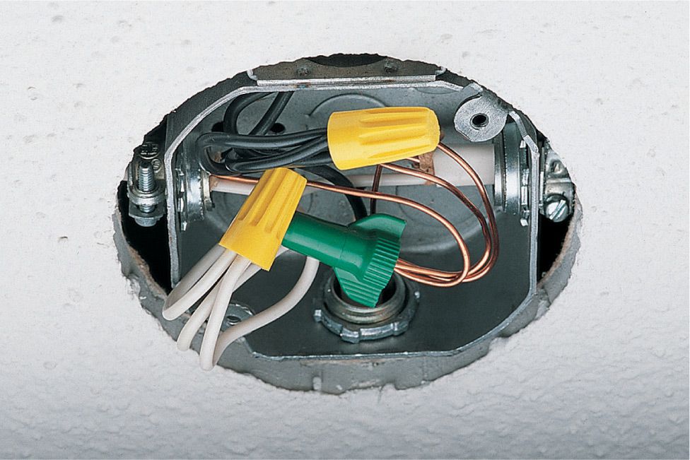
Problem: Open electrical boxes create a fire hazard if a short circuit causes sparks (arcing) inside the box.
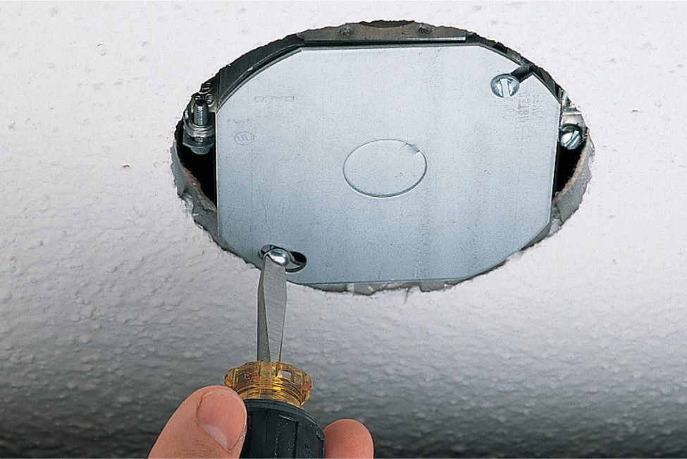
Solution: Cover an open metal box with a solid metal cover plate. Cover an open plastic box with a plastic cover plate. Cover plates are available at any hardware store. Electrical boxes must remain accessible and cannot be sealed inside ceilings or walls.
Problem: Short wires are difficult to handle. The NEC requires that each wire in an electrical box have at least 3" of workable length from the front of the box.
Solution: Lengthen circuit wires by connecting them to short pigtail wires using wire connectors. Pigtails can be cut from scrap wire but should be the same gauge and color as the circuit wires and at least 3" long.
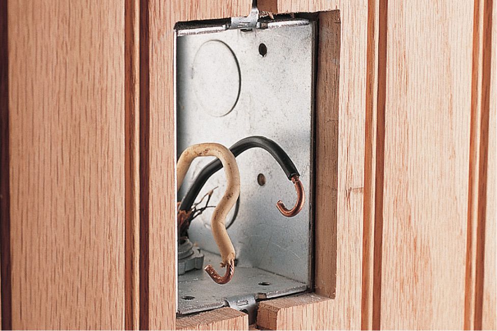
Problem: A recessed electrical box is hazardous, especially if the wall or ceiling surface is made from a flammable material, such as wood paneling. The NEC prohibits this type of installation.
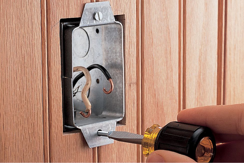
Solution: Add an extension ring to bring the face of the electrical box flush with the surface. Extension rings come in several sizes and are available at hardware stores.
Problem: Open electrical boxes create a fire hazard if a short circuit causes sparks (dust and dirt in an electrical box can cause hazardous high-resistance short circuits). When making routine electrical repairs, always check the electrical boxes for dust and dirt buildup.
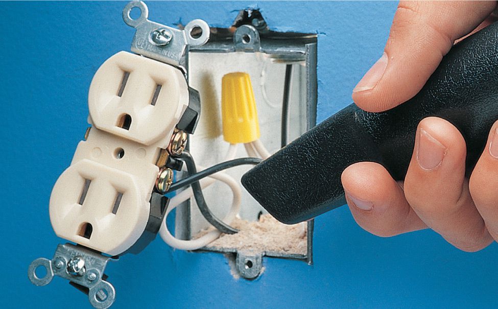
Solution: Vacuum the electrical box clean using a narrow nozzle attachment. Make sure power to the box is turned off at the panel before vacuuming.
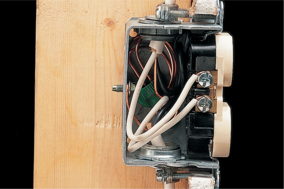
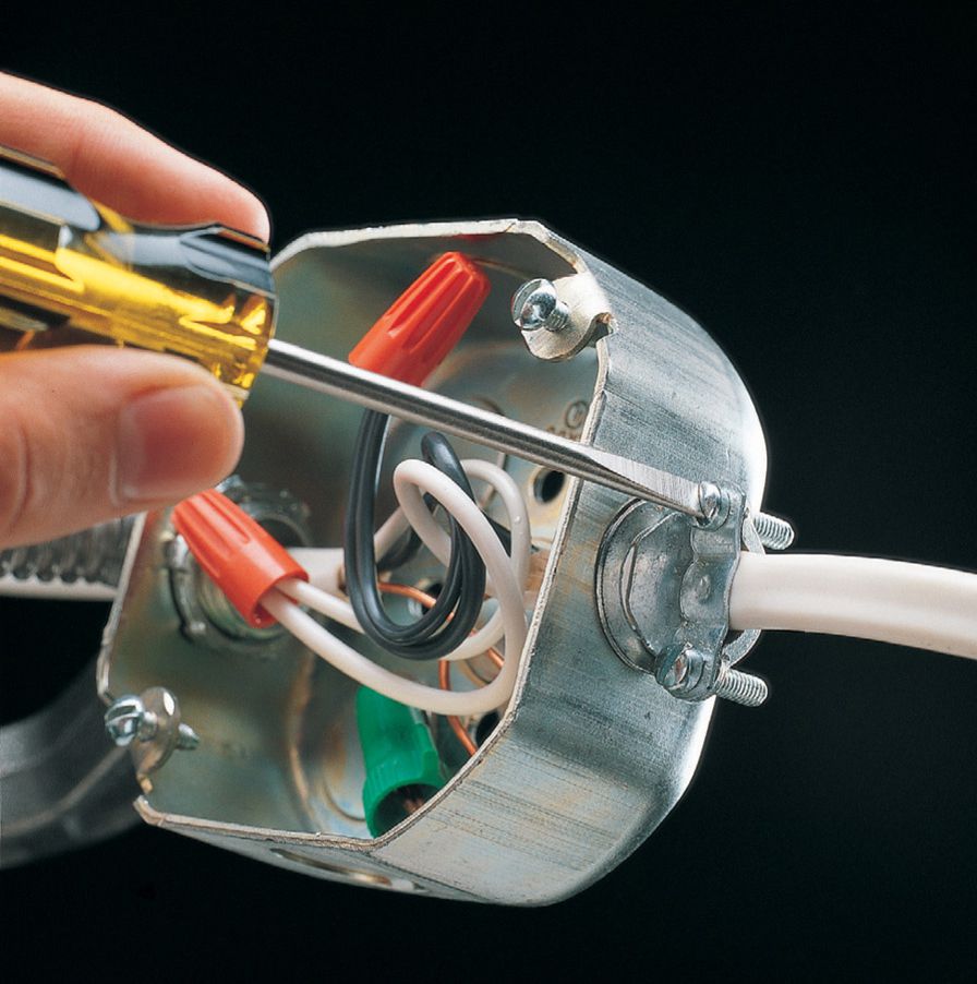
Problem: A crowded electrical box (shown cutaway) makes electrical repairs difficult. This type of installation is prohibited, because the heat in the box can damage the wire or device and cause a fire.
Solution: Replace the electrical box with a deeper electrical box.
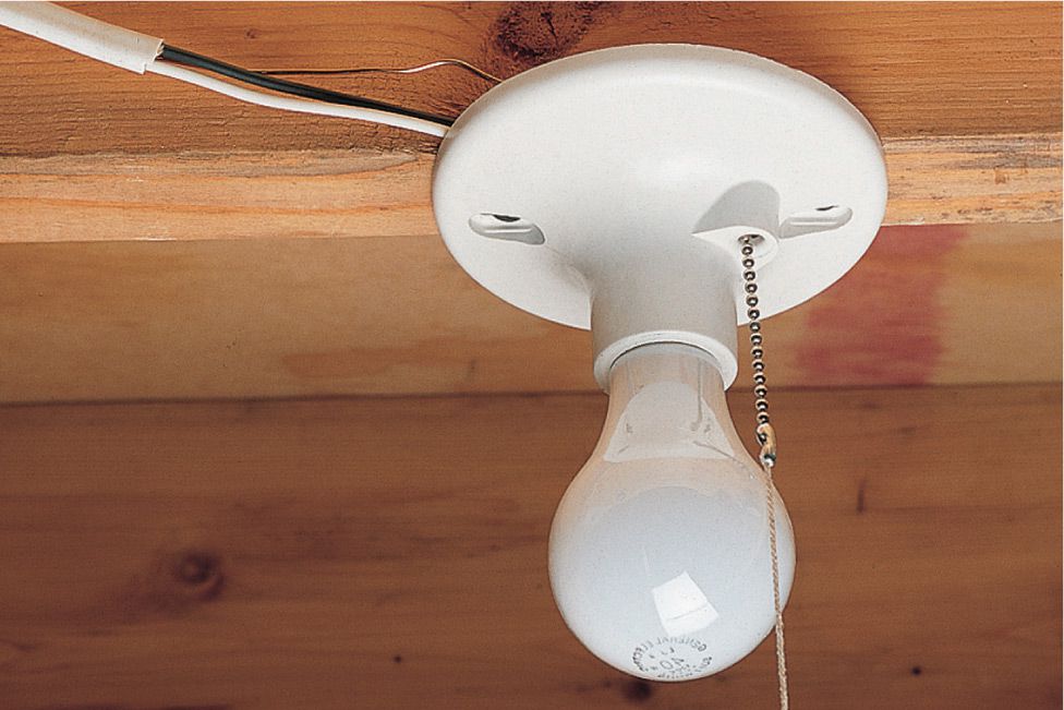
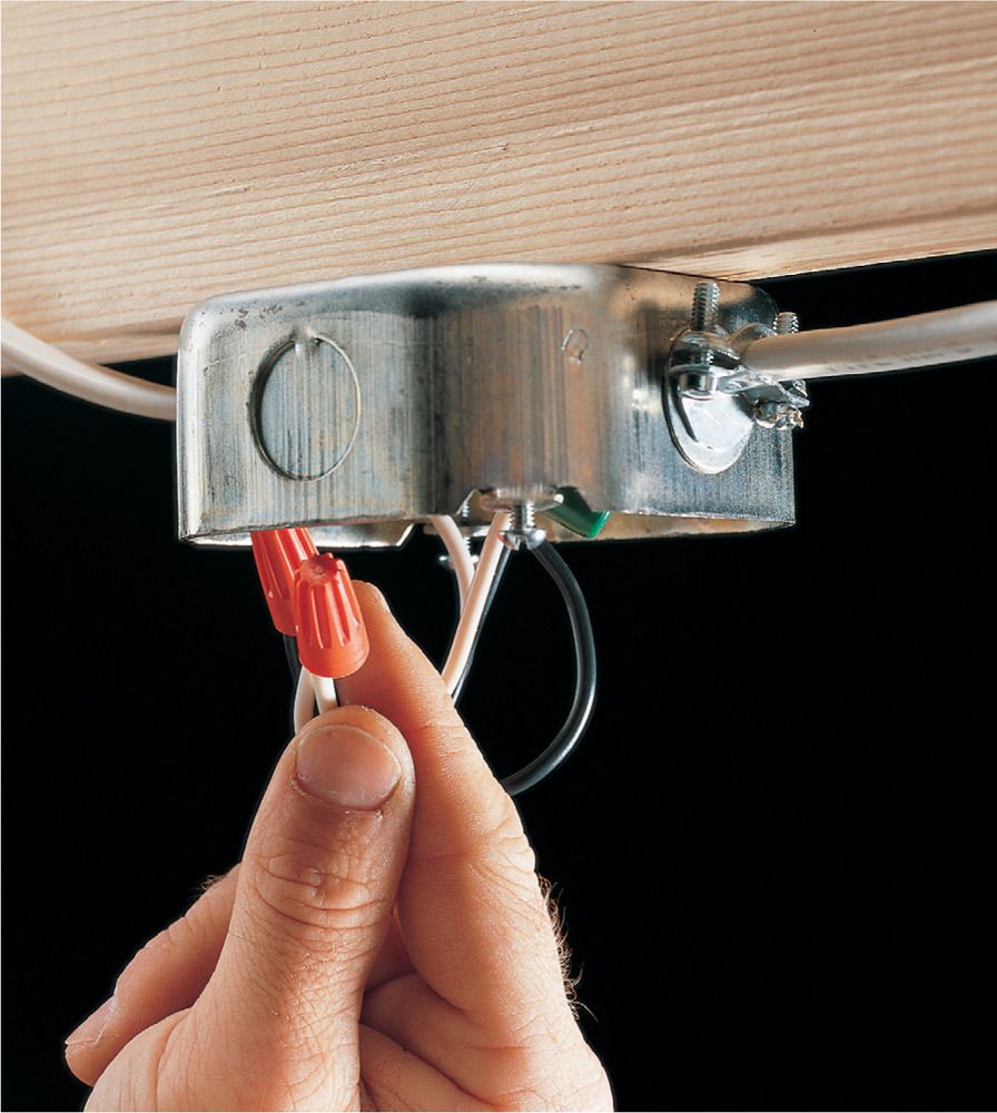
Problem: A light fixture is installed without an electrical box. This installation exposes the wiring connections and provides no support for the light fixture.
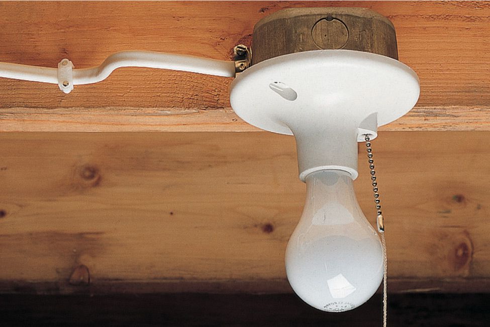
Solution: Install an approved electrical box to enclose the wire connections and support the light fixture.
![]() Common Electrical Cord Problems
Common Electrical Cord Problems

Problem: A lamp or appliance cord runs underneath a rug. Foot traffic can wear off insulation, creating a short circuit that can cause fire or shock.
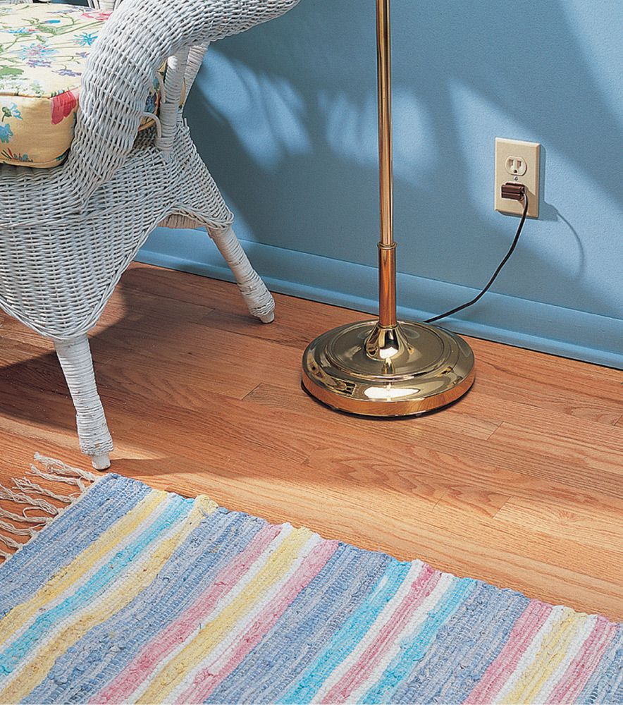
Solution: Reposition the lamp or appliance so that the cord is visible. Replace worn cords.
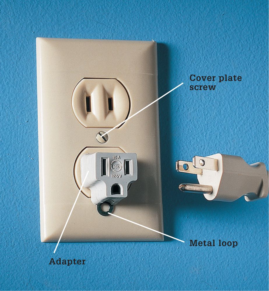
Problem: Three-prong appliance plugs do not fit a two-slot receptacle. Do not use three-prong adapters unless the metal loop on the adapter is tightly connected to the cover plate screw on receptacle.
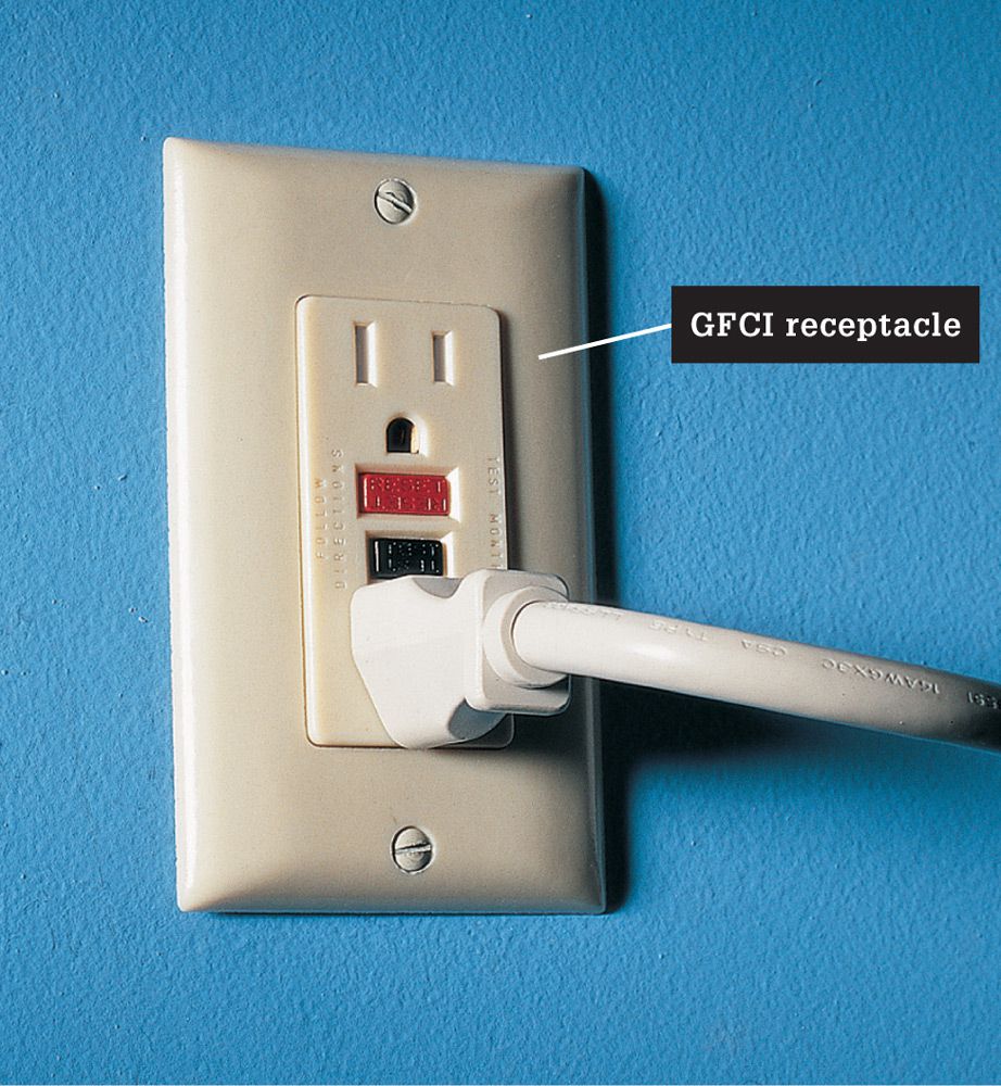
Solution: Install a three-prong grounded receptacle if a means of grounding exists at the box. Install a GFCI receptacle in kitchens and bathrooms or if the electrical box is not grounded. Label the receptacle: “No Equipment Ground”.
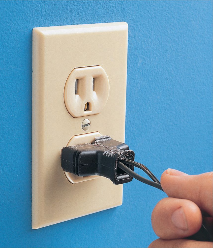
Problem: A lamp or appliance plug is cracked, or an electrical cord is frayed near the plug. Worn cords and plugs create a fire and shock hazard.
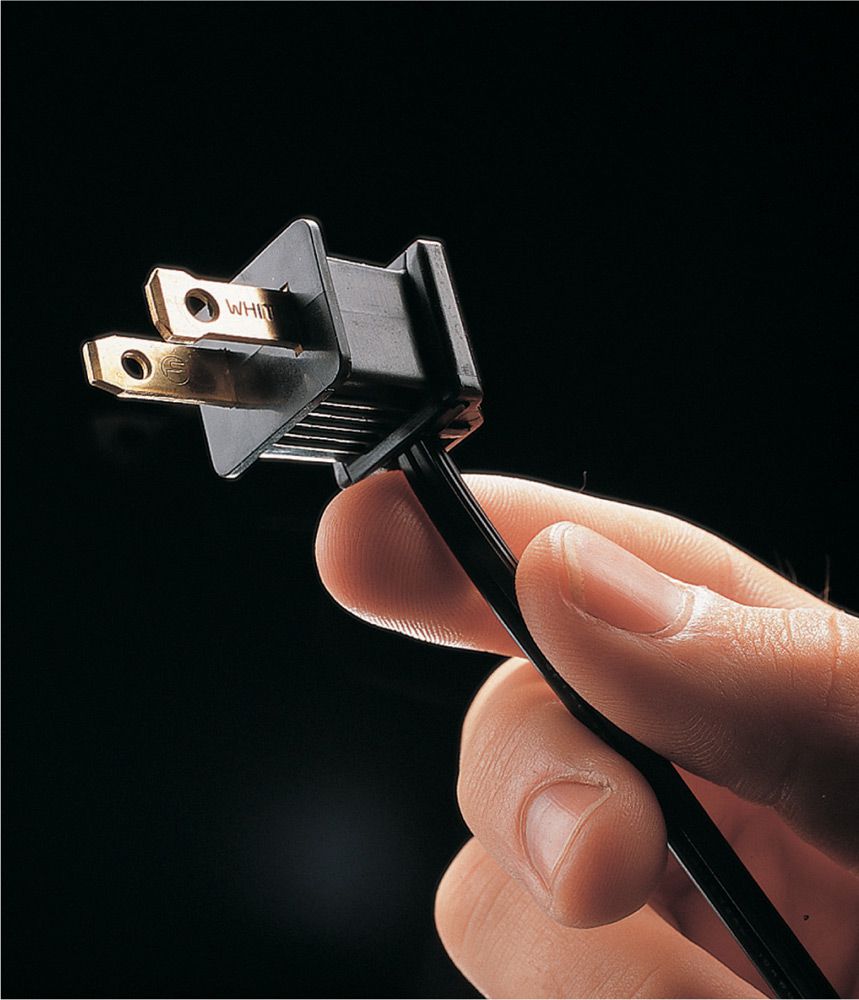
Solution: Cut away damaged portions of wire, and install a new plug (see pages 310 to 311). Replacement plugs are available at appliance stores and home centers.

Problem: An extension cord is too small for the power load drawn by a tool or appliance. Undersized extension cords can overheat, melting the insulation and leaving bare wires exposed.

Solution: Use an extension cord with wattage and amperage ratings that meet or exceed the rating of the tool or appliance. Extension cords are for temporary use only. Never use an extension cord for a permanent installation.
![]() Inspecting Receptacles & Switches
Inspecting Receptacles & Switches
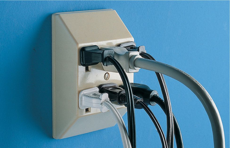
Problem: Octopus receptacle attachments used permanently can overload a circuit and cause overheating of the receptacle.

Solution: Use a multi-receptacle power strip with built-in overload protection. This is for temporary use only. If the need for extra receptacles is frequent, upgrade the wiring system.
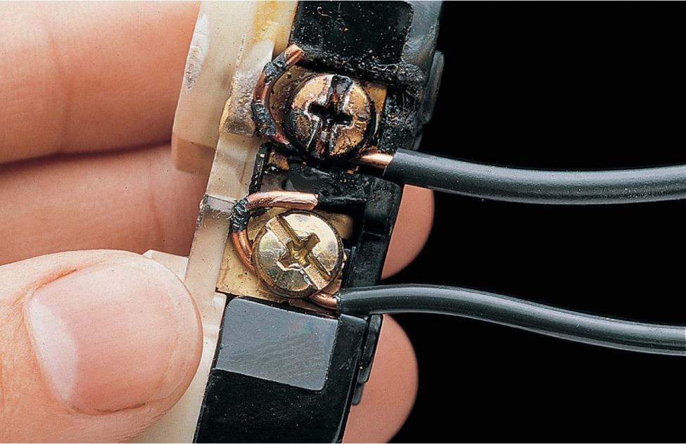
Problem: Scorch marks near screw terminals indicate that electrical arcing has occurred. Arcing usually is caused by loose wire connections.
Solution: If the insulation is damaged, cut the wires back to intact insulation. Otherwise, clean the wires with fine grit sandpaper or steel wool. Replace the receptacle. Make sure wires are connected securely to screw terminals.
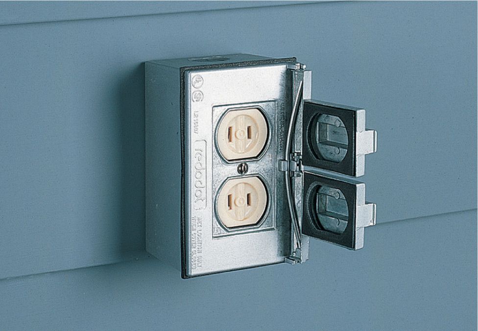
Problem: An exterior receptacle box allows water to enter the box when receptacle slots are in use.
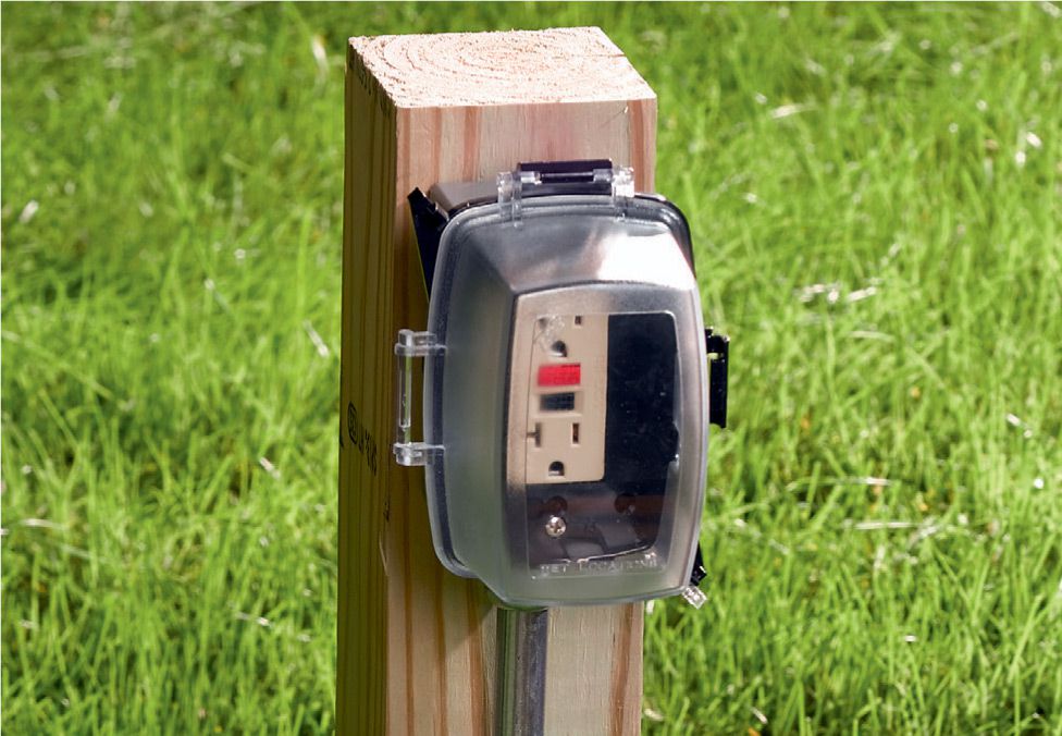
Solution: Replace the old receptacle box (no longer code compliant) with an in-use box that has a bubble cover to protect plugs from water while they are in the slots.
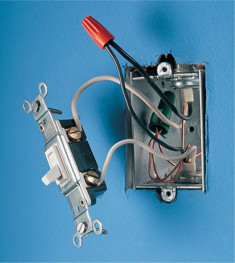
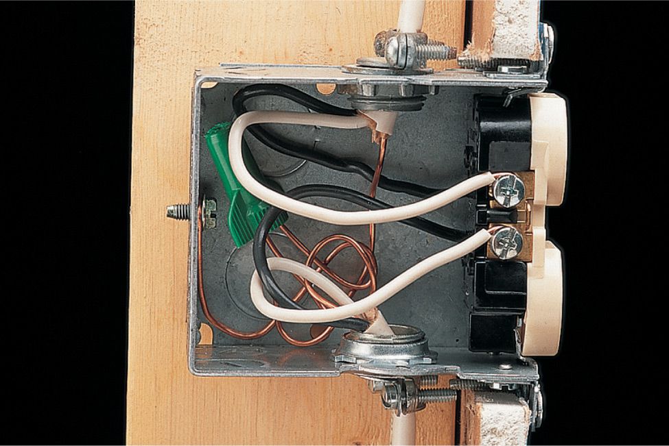
Problem: White neutral wires are connected to a switch. Although the switch appears to work correctly in this installation, it is dangerous because the light fixture carries voltage when the switch is off.
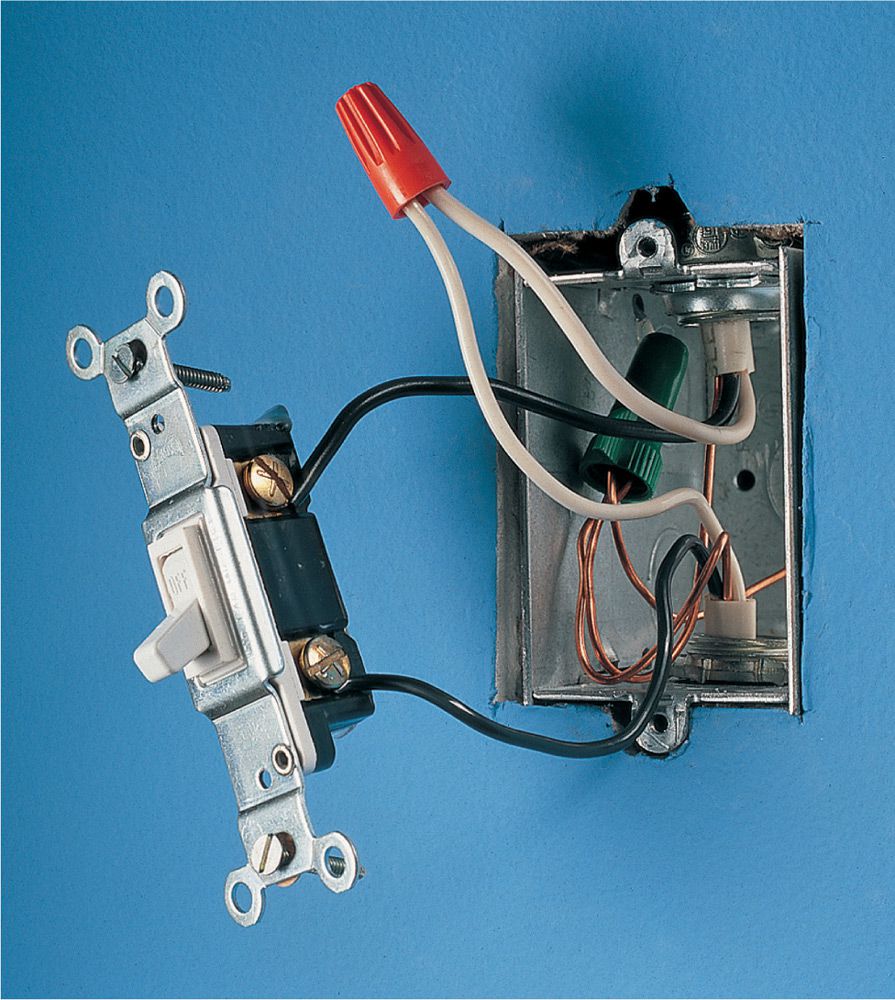
Solution: Connect the black hot wires to the switch, and join the white wires together with a wire connector.

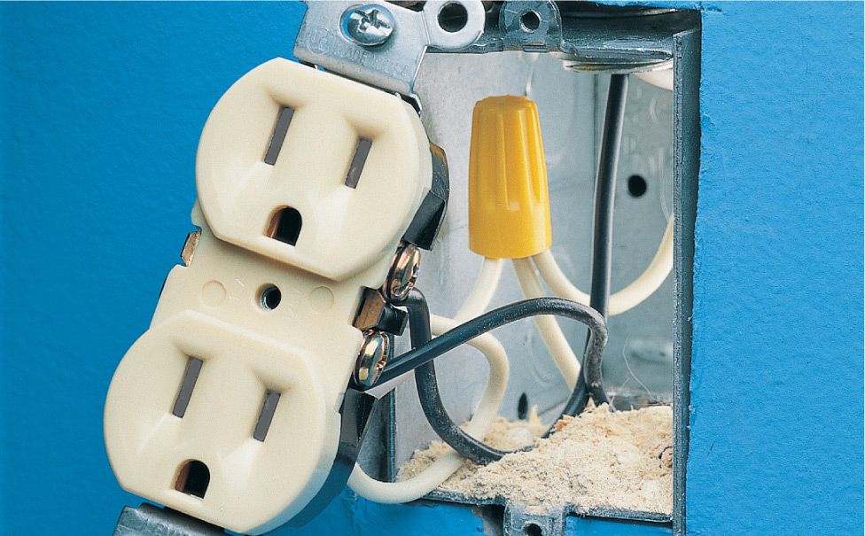
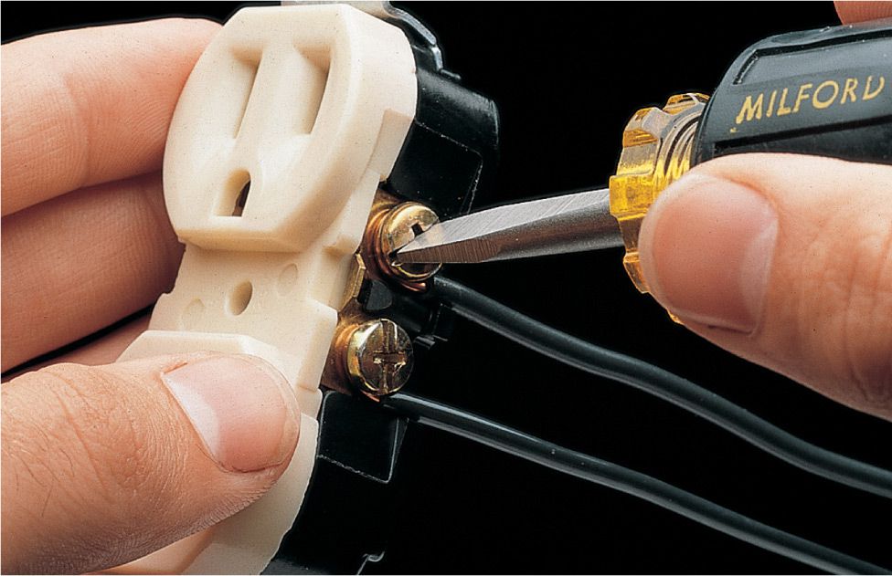
Problem: White neutral wires are connected to the brass screw terminals on the receptacle, and black hot wires are attached to silver screw terminals. This installation is hazardous because live voltage flows into the long neutral slot on the receptacle.
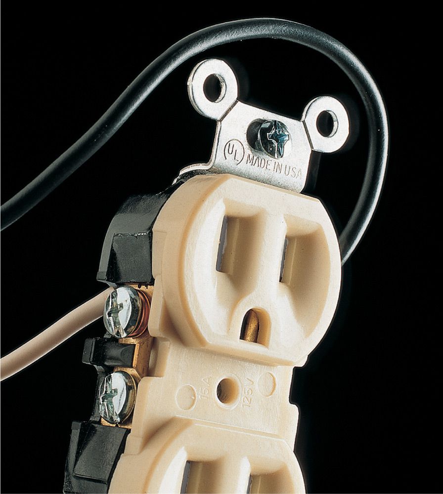
Solution: Reverse the wire connections so that the black hot wires are attached to brass screw terminals and white neutral wires are attached to silver screw terminals. Live voltage now flows into the short slot on the receptacle.