The Complete Guide to Wiring, Updated 6th Edition: Current with 2014-2017 Electrical Codes - Black & Decker, Cool Springs Press (2014)
Chapter 8. Common Wiring Projects
The instructions that follow show you how to accomplish the most popular home wiring projects. Refer to pertinent sections elsewhere in the book to find background information on tools and skills needed to get the job done.
In this chapter:
![]() GFCI & AFCI Breakers
GFCI & AFCI Breakers
![]() Whole-House Surge Arrestors
Whole-House Surge Arrestors
![]() Service Panels
Service Panels
![]() Grounding & Bonding a Wiring System
Grounding & Bonding a Wiring System
![]() Subpanels
Subpanels
![]() 120/240-Volt Dryer Receptacles
120/240-Volt Dryer Receptacles
![]() 120/240-Volt Range Receptacles
120/240-Volt Range Receptacles
![]() Ceiling Lights
Ceiling Lights
![]() Recessed Ceiling Lights
Recessed Ceiling Lights
![]() Track Lights
Track Lights
![]() Undercabinet Lights
Undercabinet Lights
![]() Vanity Lights
Vanity Lights
![]() Low-Voltage Cable Lights
Low-Voltage Cable Lights
![]() Hard-Wired Smoke & CO Alarms
Hard-Wired Smoke & CO Alarms
![]() Landscape Lights
Landscape Lights
![]() Doorbells
Doorbells
![]() Programmable Thermostats
Programmable Thermostats
![]() Wireless Switches
Wireless Switches
![]() Baseboard Heaters
Baseboard Heaters
![]() Wall Heaters
Wall Heaters
![]() Underfloor Radiant Heat Systems
Underfloor Radiant Heat Systems
![]() Ceiling Fans
Ceiling Fans
![]() Remote-Control Ceiling Fan Retrofit
Remote-Control Ceiling Fan Retrofit
![]() Bathroom Exhaust Fans
Bathroom Exhaust Fans
![]() Range Hoods
Range Hoods
![]() Backup Power Supply
Backup Power Supply
![]() Installing a Transfer Switch
Installing a Transfer Switch
![]() Outbuildings
Outbuildings
![]() Motion-Sensing Floodlights
Motion-Sensing Floodlights
![]() Standalone Solar Lighting System
Standalone Solar Lighting System
![]() GFCI & AFCI Breakers
GFCI & AFCI Breakers
Understanding the difference between GFCI (ground-fault circuit interrupter) and AFCI (arc fault circuit interrupter) is tricky for most homeowners. Essentially it comes down to this: Arc-fault interrupters keep your house from burning down; ground-fault interrupters keep people from being electrocuted.
The National Electric Code (NEC) requires that an AFCI breaker be installed on most branch circuits that supply outlets or fixtures in newly constructed homes. The NEC also requires adding AFCI protection to these circuits when you add new circuits and modify or extend existing circuits. They’re a prudent precaution in any home, especially if it has older wiring. AFCI breakers will not interfere with the operation of GFCI receptacles, so it is safe to install an AFCI breaker on a circuit that contains GFCI receptacles.
GROUND-FAULT CIRCUIT-INTERRUPTERS
A GFCI is an important safety device that disconnects a circuit in the event of a ground fault (when current takes a path other than the neutral back to the panel).
On new construction, GFCI protection is required for receptacles in these locations: kitchen counter tops, bathrooms, garages, unfinished basements, crawlspaces, outdoors, within six feet of sinks, and in unfinished accessory buildings such as storage and work sheds. In general it is a good practice to protect all receptacle and fixture locations that could encounter damp or wet circumstances.
Tools & Materials ![]()
Insulated screwdriver
Circuit tester
Combination tool
AFCI or GFCI breaker
ARC-FAULT CIRCUIT INTERRUPTERS
AFCIs detect arcing (sparks) that can cause fires between and along damaged wires. AFCI protection is required for 15- and 20-amp, 120-volt circuits that serve living rooms, family rooms, dens, parlors, libraries, dining rooms, bedrooms, sun rooms, kitchens, laundry areas, closets, and hallways. AFCI protection is not required for circuits serving bathrooms, garages, the exterior of the home, appliances such as furnaces and air handlers.
The easiest way to provide AFCI protection for a circuit is to install an AFCI circuit breaker labeled as a “combination” device in the electrical panel. The 2014 NEC allows several alternate methods of providing AFCI protection, but you should consult an electrician before using these alternate methods. You should install combination AFCI circuit breakers when installing new circuits that require AFCI protection. You should install either combination AFCI circuit breakers or AFCI receptacles when you modify, replace, or extend an existing circuit that requires AFCI protection.
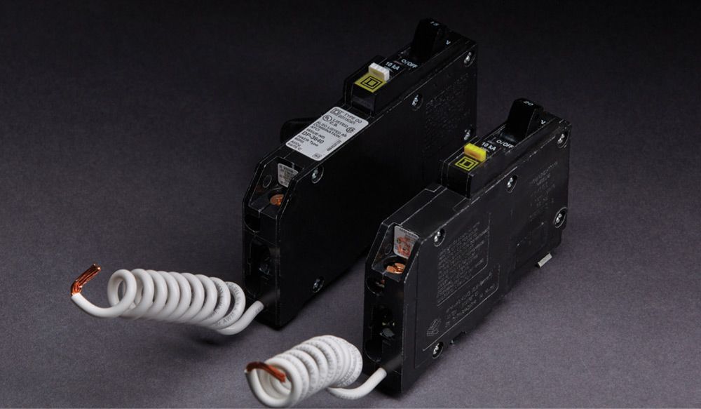
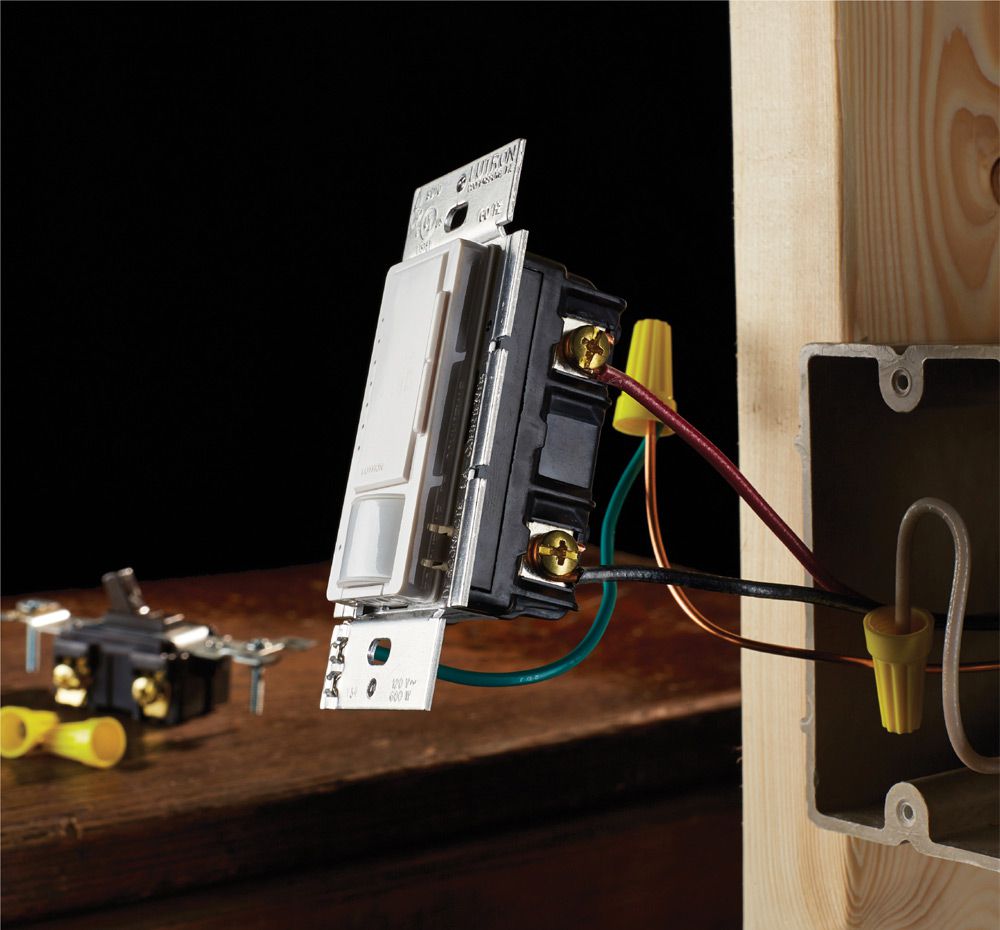
AFCI breakers are similar in appearance to GFCI breakers, but they function differently. AFCI breakers trip when they sense an arc fault. GFCI breakers trip when they sense fault between the hot wire and the ground.
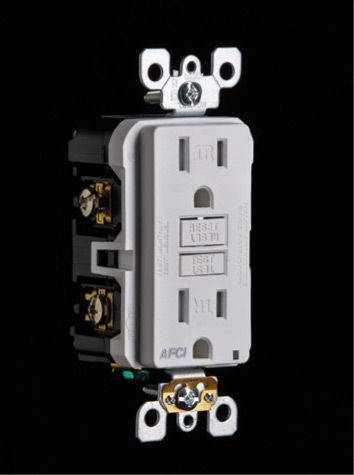
An AFCI-protected receptacle
![]() How to Install an AFCI or GFCI Breaker
How to Install an AFCI or GFCI Breaker
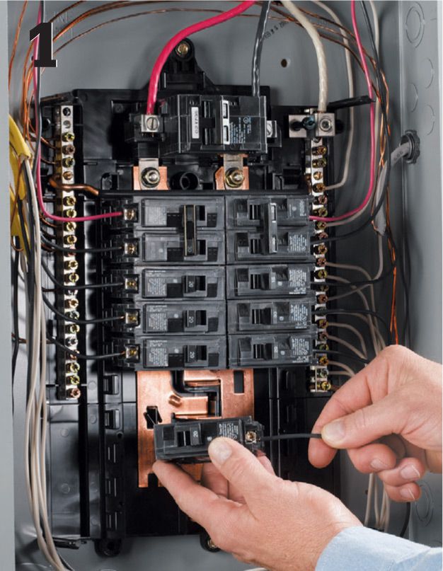
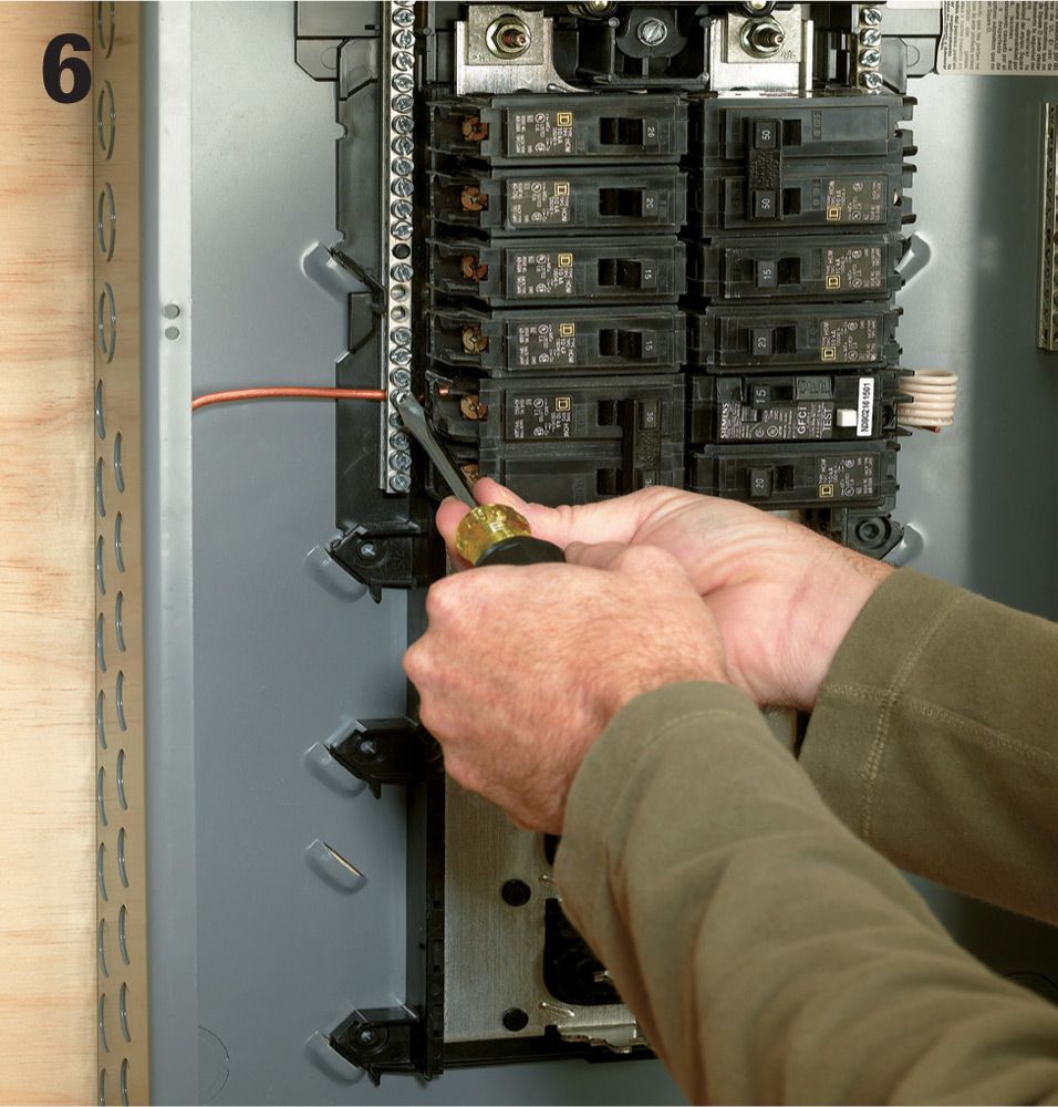
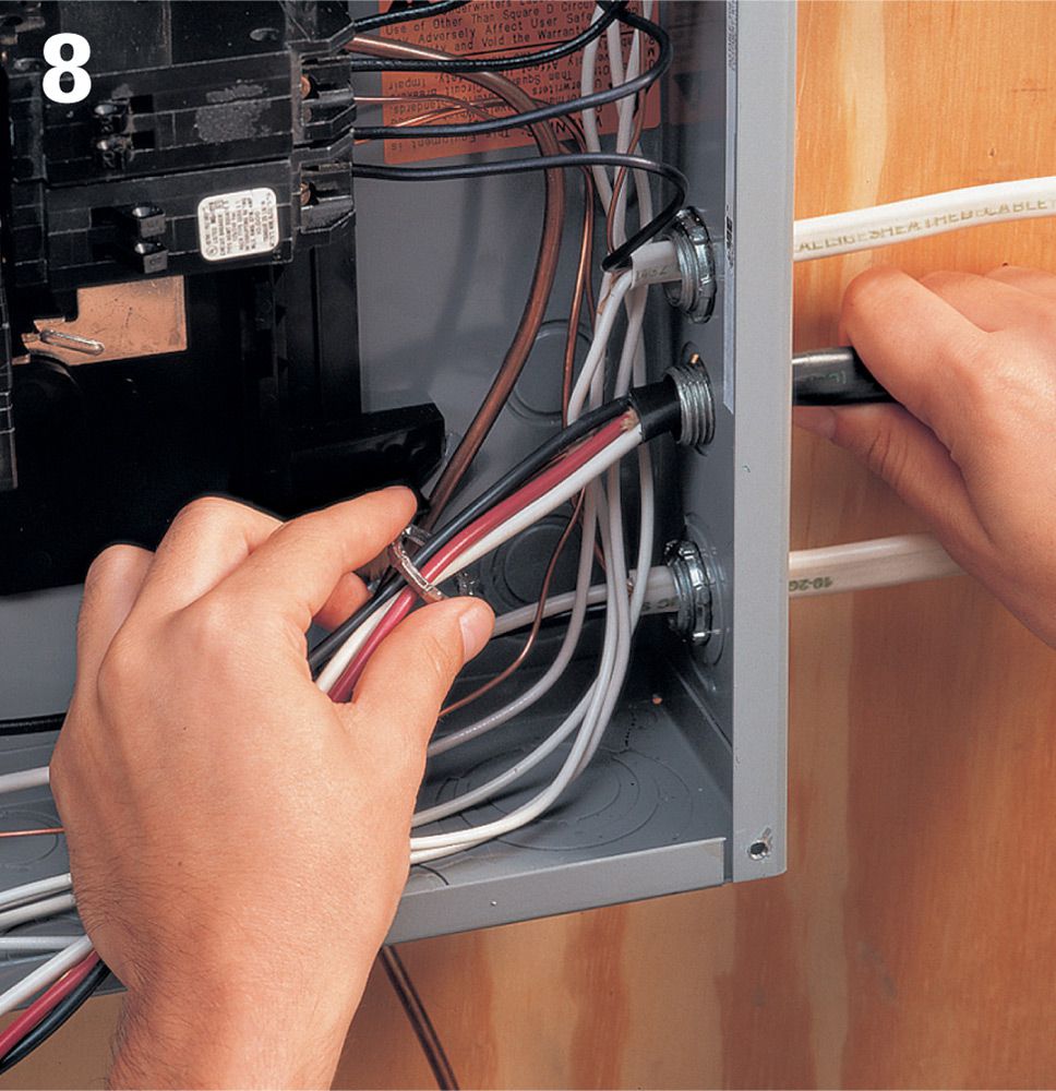
Locate the breaker for the circuit you’d like to protect. Turn off the main circuit breaker. Remove the cover from the panel, and test to ensure that power is off (see page 80). Remove the breaker you want to replace from the panel. Remove the black wire from the LOAD terminal of the breaker.
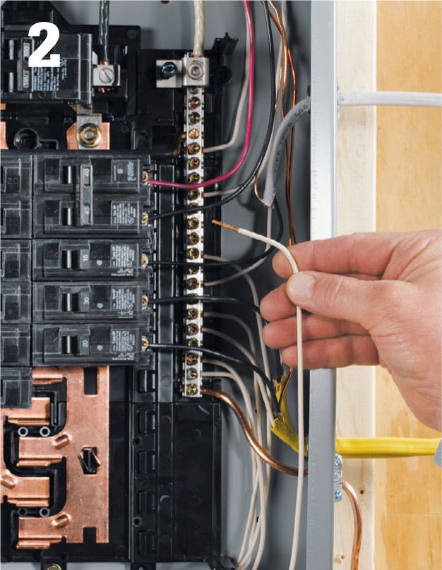
Find the white wire on the circuit you want to protect, and remove it from the neutral bus bar.
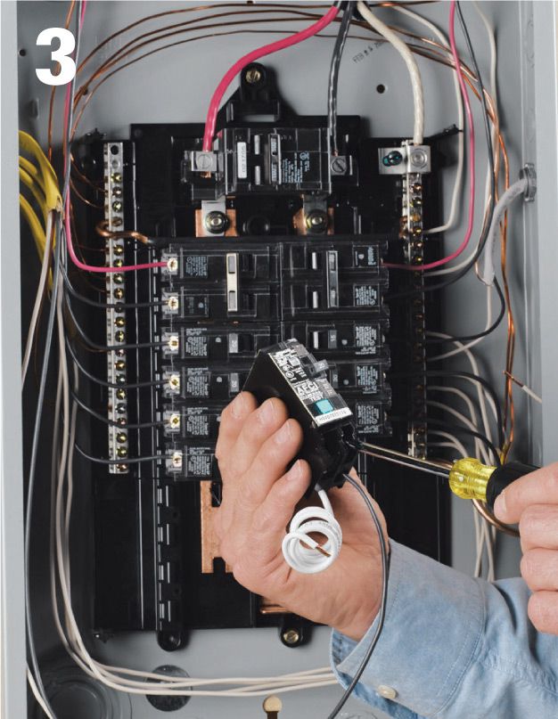
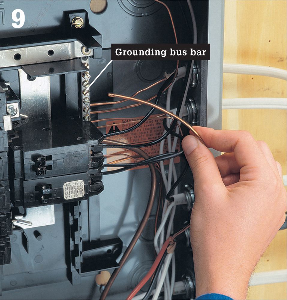
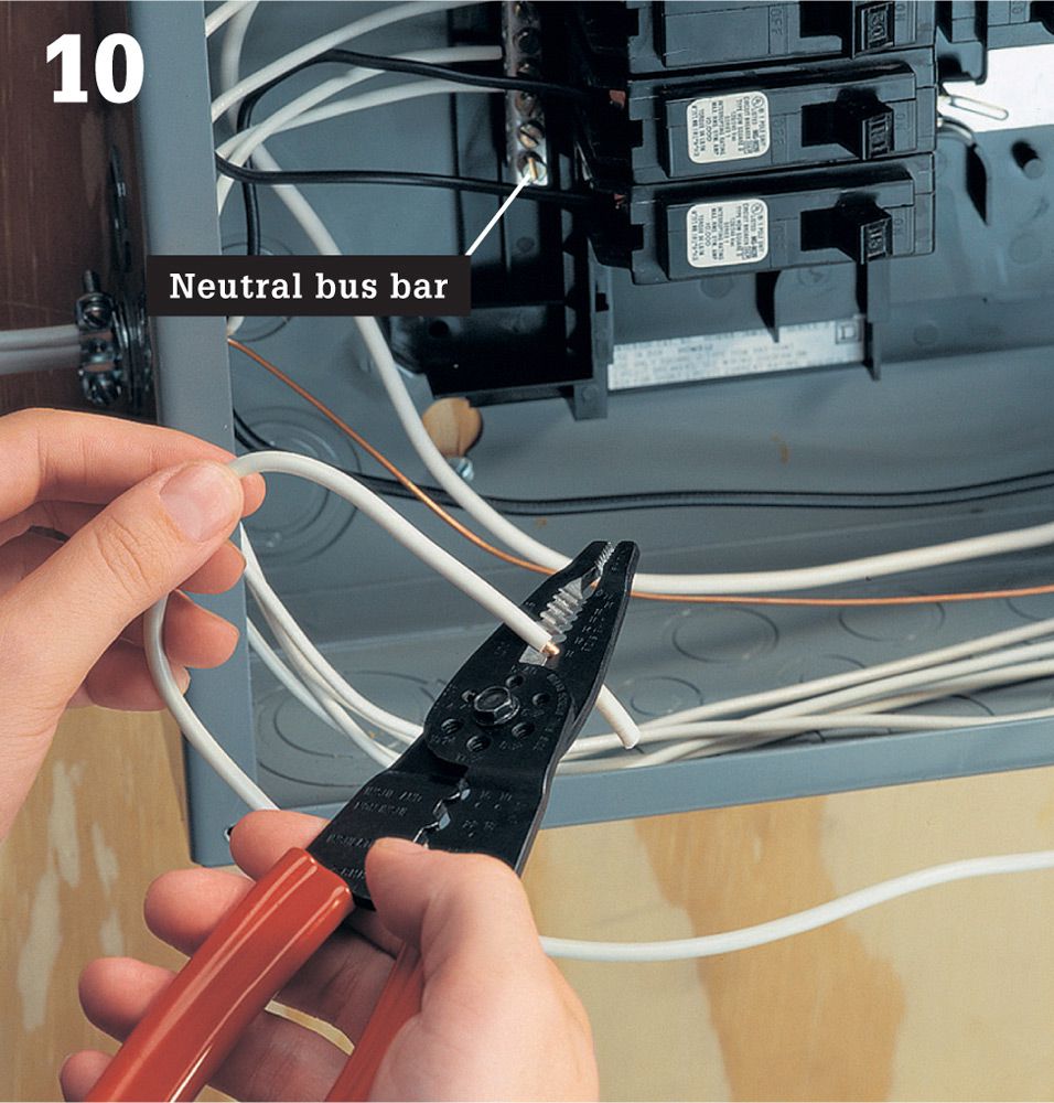
Flip the handle of the new AFCI or GFCI breaker to OFF. Loosen both of the breaker’s terminal screws. Connect the white circuit wire to the breaker terminal labeled PANEL NEUTRAL. Connect the black circuit wire to the breaker terminal labeled LOAD POWER.
Connect the new breaker’s coiled white wire to the neutral bus bar on the service panel.
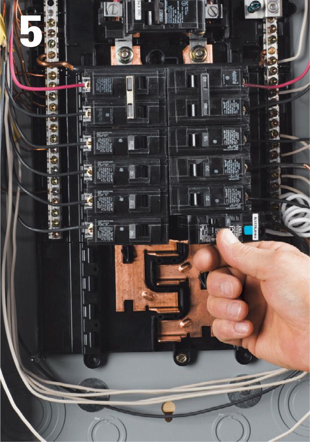
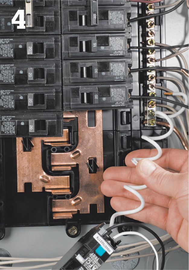
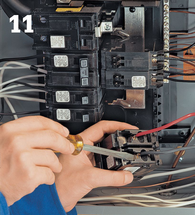
Make sure all the connections are tight. Snap the new breaker into the bus bar.
Turn the main breaker on. Turn off and unplug all fixtures and appliances on the AFCI or GFCI breaker circuit. Turn the AFCI or GFCI breaker on. Press the test button. If the breaker is wired correctly, the breaker trips open. If it doesn’t trip, check all connections or consult an electrician. Replace the panel cover.
![]() Whole-House Surge Arrestors
Whole-House Surge Arrestors
Electrical surges caused by lighting or utility malfunctions can destroy or seriously damage sensitive electronics. Many homes contain tens of thousands of dollars worth of computers and home entertainment equipment protected by no more than a $10 plug-in surge suppressor. While these devices do afford a modest level of protection, they are no match for the voltage a lightning strike will push through a system. And they offer no protection for the wiring itself. Whole-house surge arrestors provide comprehensive protection for the wiring and devices attached to it.
Whole-house surge arrestors are available in two basic types. One type is wired on the utility side of the panel, normally at the meter. When installed by a licensed electrician, these devices provide the highest level of protection, shielding the panel and all electrical devices in the house. The other type wires directly into the panel and protects all circuits originating at that panel. Manufacturers offer units that are housed in separate boxes (these look like a small subpanel) as well as models that are designed to replace a double-pole breaker in the panel itself. These install like standard breakers. Both types provide protection for the whole house. Freestanding models are also available with separate protection for phone, data, and cable-television lines—a wise addition if you need to protect networked computers or cable-TV receivers.
Whatever style you choose, look for models with the Underwriters Laboratories 1449 rating and indicator lights showing that the system is protected. Most manufacturers also include a warranty against defect that covers a certain amount of property damage.
Tools & Materials ![]()
Hammer
Combination tool
Screwdrivers
Cable ripper
Linesman’s pliers
Circuit tester
Crimping tools
Whole-house surge arrestor
Conduit nipple and locknuts
Two 15- or 20-amp single-pole breakers
Coaxial cable and terminators
UTP cable and terminators
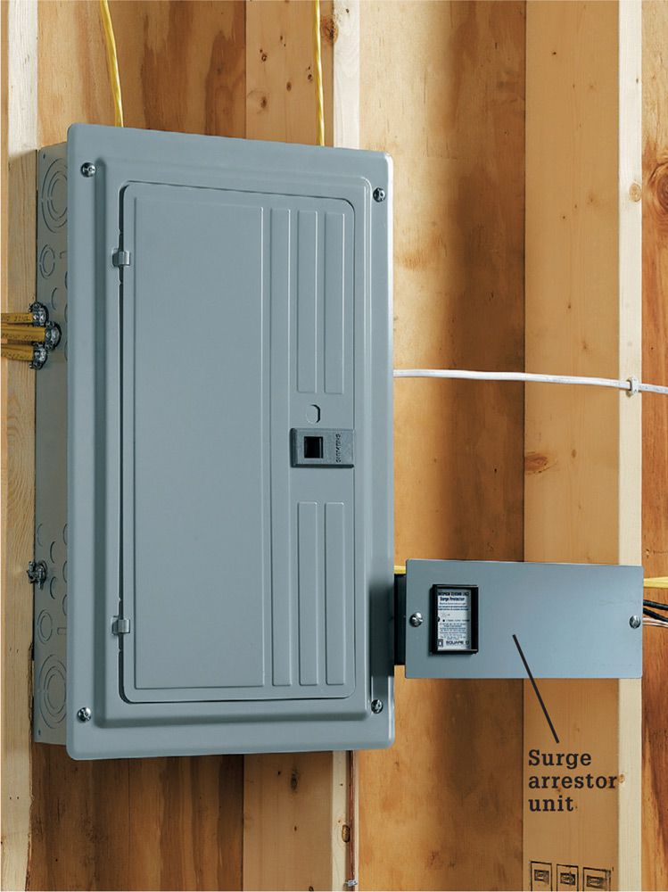
A Whole-house surge arrestor is an inexpensive defense against expensive damage from high-voltage shocks caused by lightning strikes and power surges. Most models install next to the main panel.
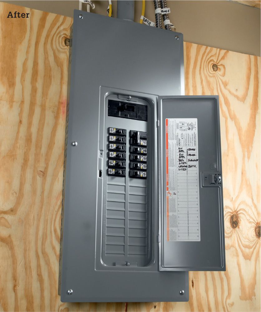
A surge arrestor installed at the panel protects all downstream connected devices and wires.
![]() How to Install a Whole-House Surge Arrestor
How to Install a Whole-House Surge Arrestor
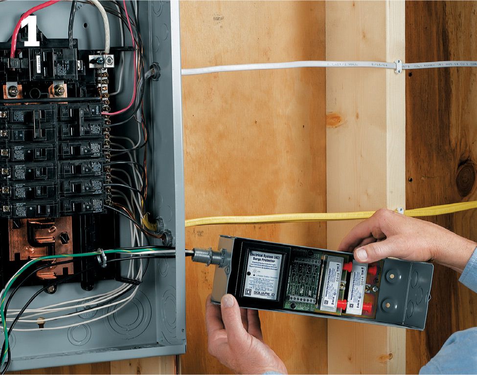
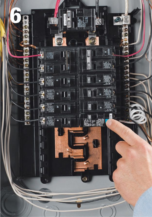
Turn off power at the main breaker. Remove the cover, and test to make sure the power is off. Mount the arrestor near the service panel following the manufacturer’s instructions. Typically the arrestor mounts on one side of the panel so its knockout lines up with a lower knockout on the panel. Remove the knockout on the panel. Install a conduit nipple on the arrestor, and thread the wires from the arrestor through the nipple and into the panel. Slip the other end of the nipple through the opening in the panel, and tighten the locknut. Secure the box to the wall with screws as directed.
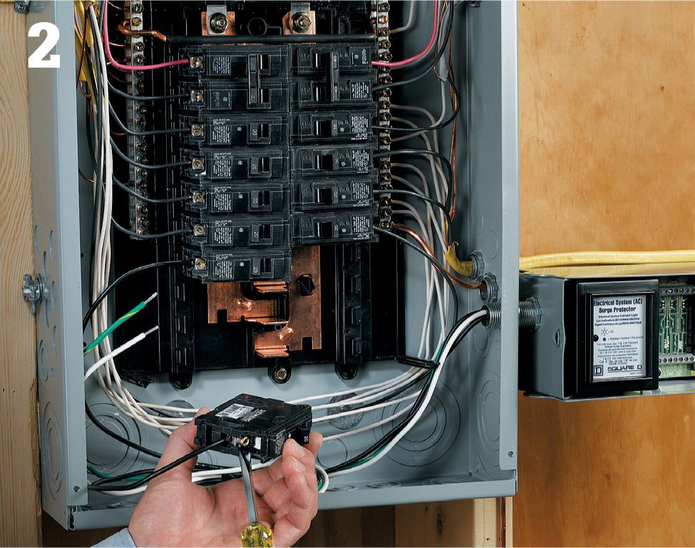
Connect the two black wires to two dedicated 15- or 20-amp breakers. Trim the wires as short as possible without making sharp bends. Connect the white neutral wire to the neutral bar and the green grounding wire to the grounding bar. Keep wire lengths as short as possible. Snap the new breakers into the bus bar. Restore the power and carefully test that the voltage between the two black arrestor leads is 240 volts. Replace the panel cover and the arrestor cover. If the arrestor has indicator lights, they should glow, showing that the system is now protected.
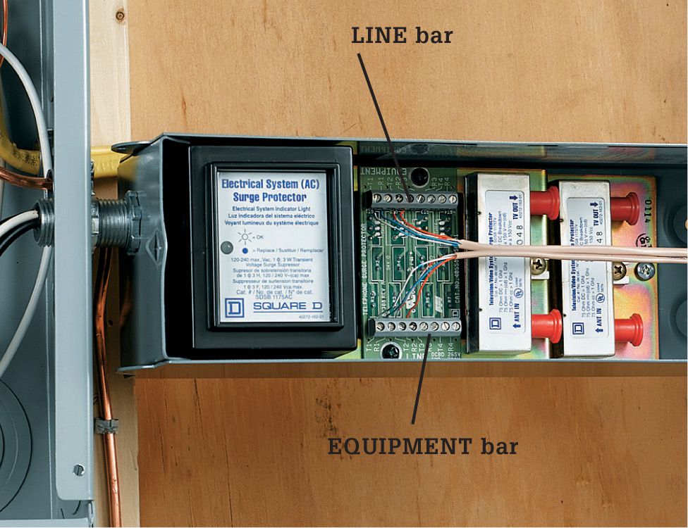
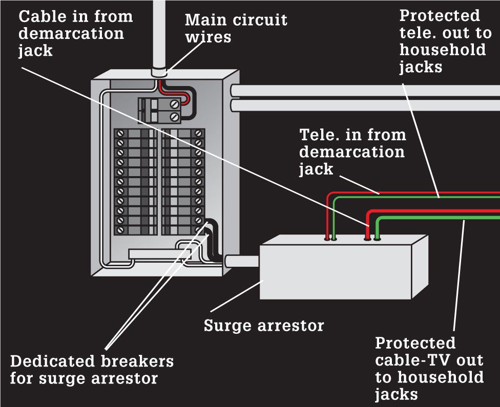
Variation: If the arrestor has separate protection for the telephone circuits, remove the cable that runs from the phone demarcation jack to the junction box. Then remove a knockout in the arrestor and route a new UTP cable from the demarcation jack to the arrestor. Strip insulation from the wires and connect them to the terminals on the LINE bar (labeled IN on some models) on the phone protection module in the arrestor. Run a UTP cable from the EQUIPMENT bar (labeled OUT on some models) to the junction box. Strip and connect the wires from this cable to the appropriate terminals in the arrestor and the junction box.
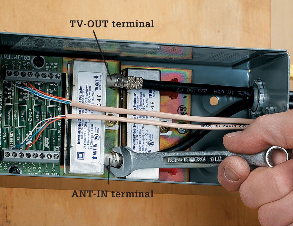
Variation: If the arrestor has separate protection for a cable television circuit, remove the appropriate knockout from the arrestor and run a coaxial cable to the arrestor from the cable-TV demarcation jack. Connect the coaxial cable to the ANT-IN terminal on the cable-TV protection module. Run another coaxial cable from the TV-OUT terminal to the cable TV junction box or the distribution panel. Do not overtighten the connections.
![]() Service Panels
Service Panels
Only a generation ago, fuse boxes were commonplace. But as our demands for power increased, homeowners replaced the 60-amp boxes with larger, safer, and more reliable circuit breaker panels. Typical new homes were built with perfectly adequate 100-amp load centers. But today, as average home size has risen to more than 2,500 sq. ft. and the number of home electronics has risen exponentially, 100 amps is often inadequate service. As a result, many homeowners have upgraded to 200-amp service, and new single-family homes often include 250 amps or even 400 amp service.
Upgrading your electrical service panel from 100 amps to 200 amps is an ambitious project that requires a lot of forethought. The first step is to obtain a permit. When you are ready to begin, you will need to have your utility company disconnect your house from electrical service at the transformer that feeds your house. When you schedule this, talk to your utility company about the size of your service drop or lateral. That may need to be upgraded too. Not only does this involve working them into your schedule, it means you will have no power during the project. You can rent a portable generator to provide a circuit or two, or you can run a couple extension cords from a friendly neighbor. But unless you are a very fast worker, plan on being without power for at least one to two days while the project is in process.
Also check with your utility company to make sure you know what equipment is theirs and what belongs to you. In most cases, the electric meter and everything on the street side belongs to the power company, and the meter base and everything on the house side is yours. Be aware that if you tamper with the sealed meter in any way, you likely will be fined. Utility companies will not re-energize your system without approval from your inspecting agency.
Upgrading a service panel is a major project. Do not hesitate to call for help at any point if you’re unsure what to do.
Tools & Materials ![]()
200-amp load center (service panel)
200-amp bypass meter base
Circuit breakers (AFCI if required by local code)
Schedule 80 or RMC conduit and fittings
Weatherhead
Service cable
Circuit wires
Plywood backer board
Screwdrivers
Drill/driver
Tape
Allen wrench
Circuit tester
Multimeter
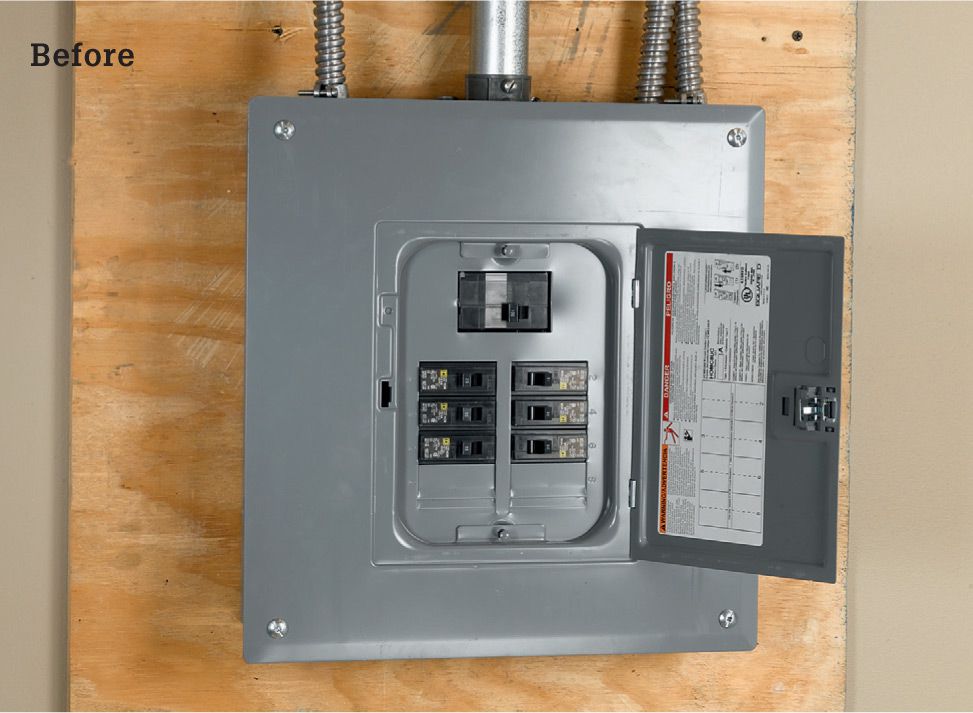
Modern homeowners consume more power than our forebears, and it is often necessary to upgrade the electrical service to keep pace. While homeowners are not allowed to make the final electrical service connections, removing the old panel and installing the new panel and meter base yourself can save you hundreds or even thousands of dollars.
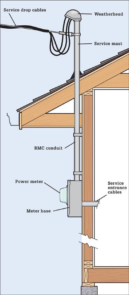
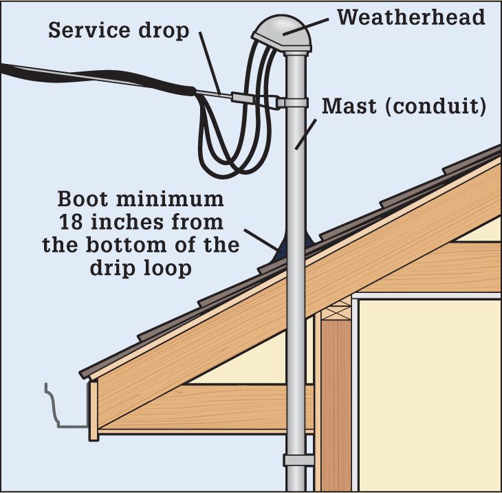
Aboveground service drop. In this common configuration, the service cables from the closest transformer (called the service drop) connect to service entrance wires near the weatherhead. This connection is called the service point and is where your property usually begins. The service entrance wires from the weatherhead are routed to a power meter that’s owned by your utility company but is housed in a base that’s considered your property. From the meter the service entrance wires enter your house through the wall and are routed to the main service panel, where they are connected to the main circuit breaker.
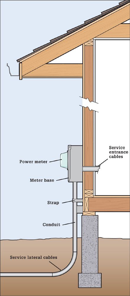
Underground service lateral. Increasingly, homebuilders are choosing to have power supplied to their new homes underground instead of an overhead service drop. Running the cables in the ground eliminates problems with power outages caused by ice accumulation or fallen trees, but it entails a completely different set of cable and conduit requirements. For the homeowner, however, the differences are minimal, because the hookups are identical once the power service reaches the meter.
Locating Your New Panel ![]()
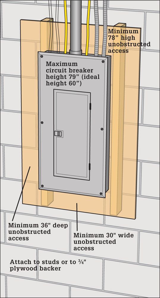
Local codes dictate where the main service panel may be placed relative to other parts of your home. Although the codes vary (and always take precedence), national codes stipulate that a service panel (or any other distribution panel) may not be located near flammable materials, in a bathroom, clothes closet or other area designated for storage, above stairway steps, or directly above a workbench or other permanent work station or appliance. The panel also can’t be located in a crawl space. If you are installing a new service entry hookup, there are many regulations regarding height of the service drop and the meter. Contact your local inspections office for specific regulations.
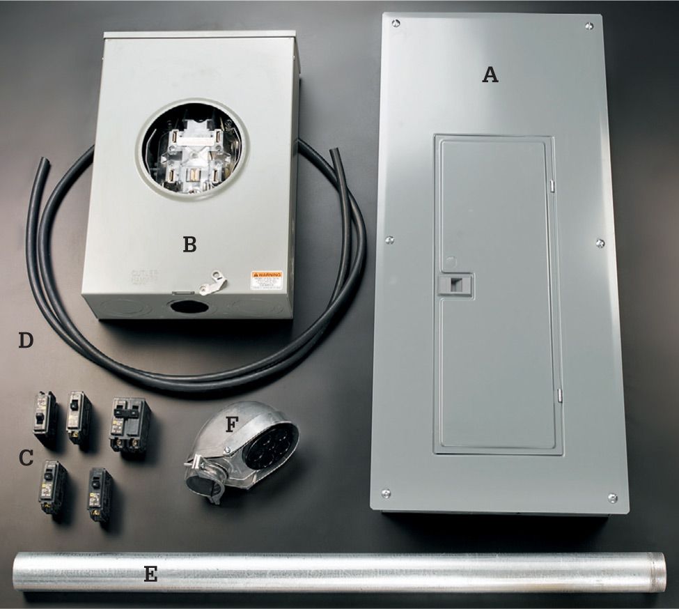
All the equipment you’ll need to upgrade your main panel is sold at most larger building centers. It includes (A) a new 200-amp panel; (B) a 200-amp bypass meter base (also called a socket); (C) individual circuit breakers (if your new panel is the same brand as your old one you may be able to reuse the old breakers); (D) new, THW, THHW, THWN-2. RHW, RHW-2, XHHW (2/0 copper seen here); (E) 2" dia. rigid metallic conduit; (F) weatherhead shroud for mast.
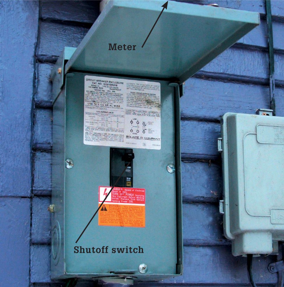
The main circuit breaker (called the service equipment) may need to be located outside next to the electric meter if your main panel is too far away from the point where the service cable enters your house. The maximum distance allowed varies widely, from as little as 3 ft. to more than 10 ft. Wiring the service cable through the shutoff has the effect of transforming your main panel into a subpanel, which will impact how the neutral and ground wires are attached (see Subpanels, pages 186 to 189).
![]() How to Replace a Main Panel
How to Replace a Main Panel
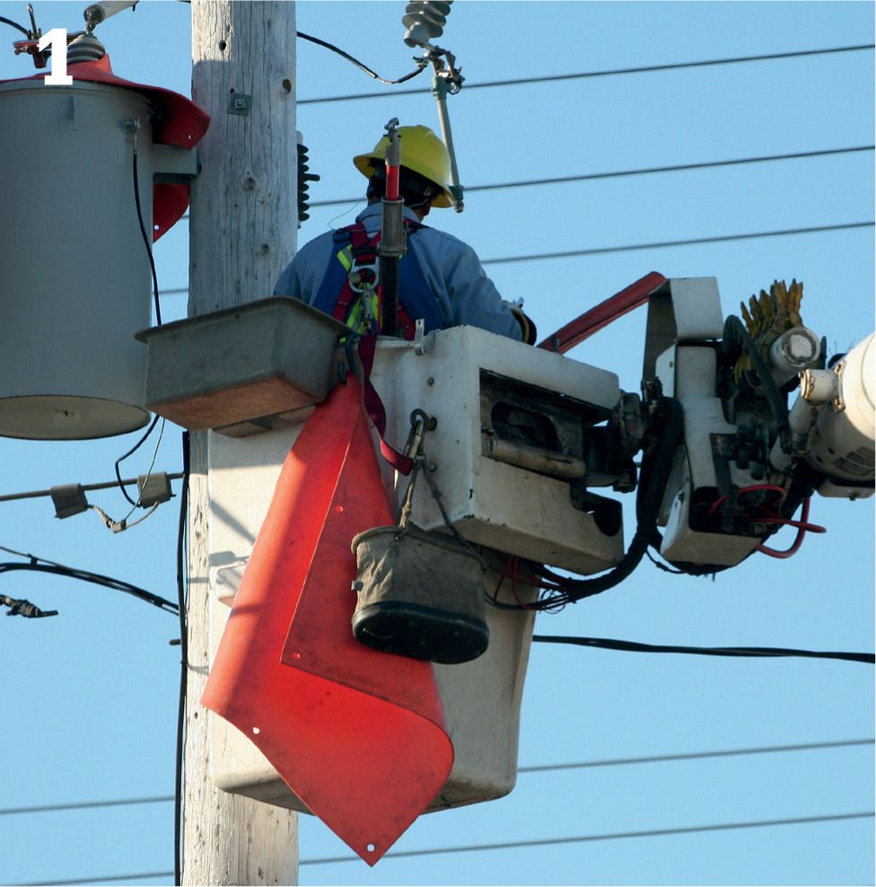
Shut off power to the house at the transformer. This must be done by a technician who is certified by your utility company. Also have the utility worker remove the old meter from the base. It is against the law for a homeowner to break the seal on the meter.
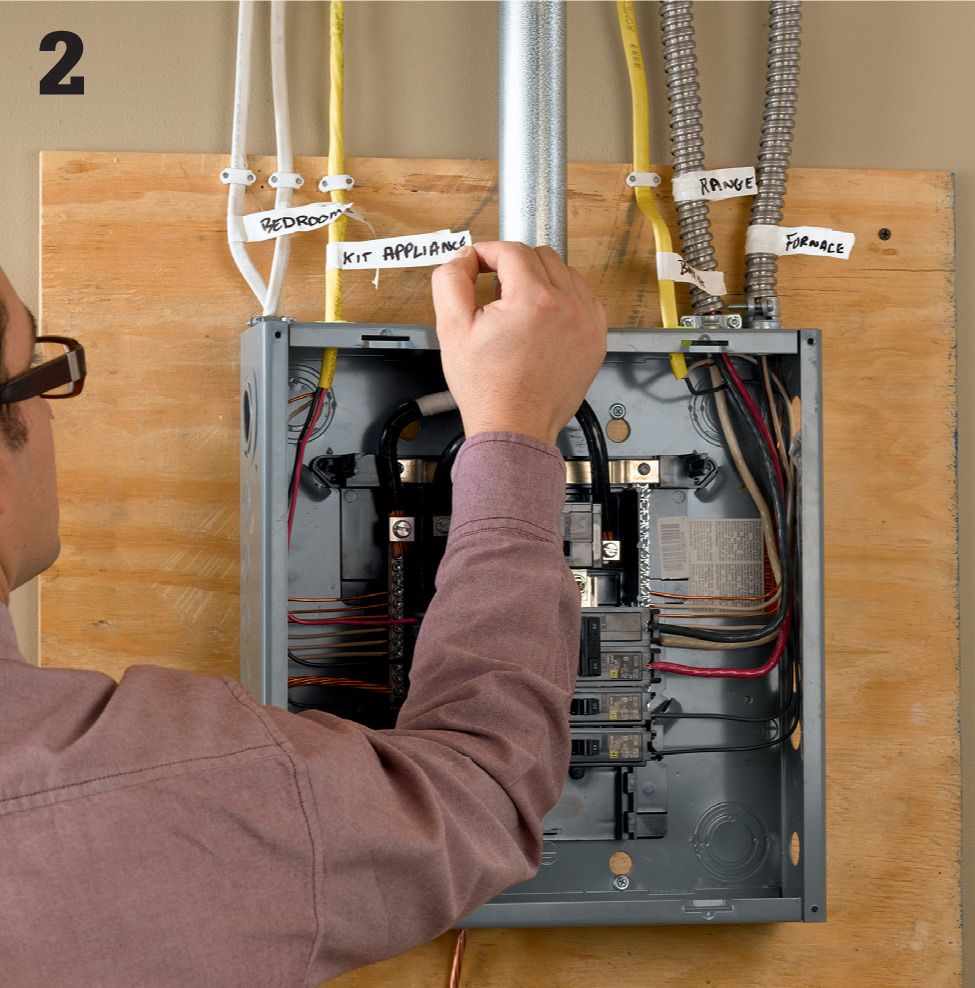
Label all incoming circuit wires before disconnecting them. Labels should be written clearly on tape that is attached to the cables outside of the existing service panel. Test the circuits before starting to make sure they are labeled correctly.
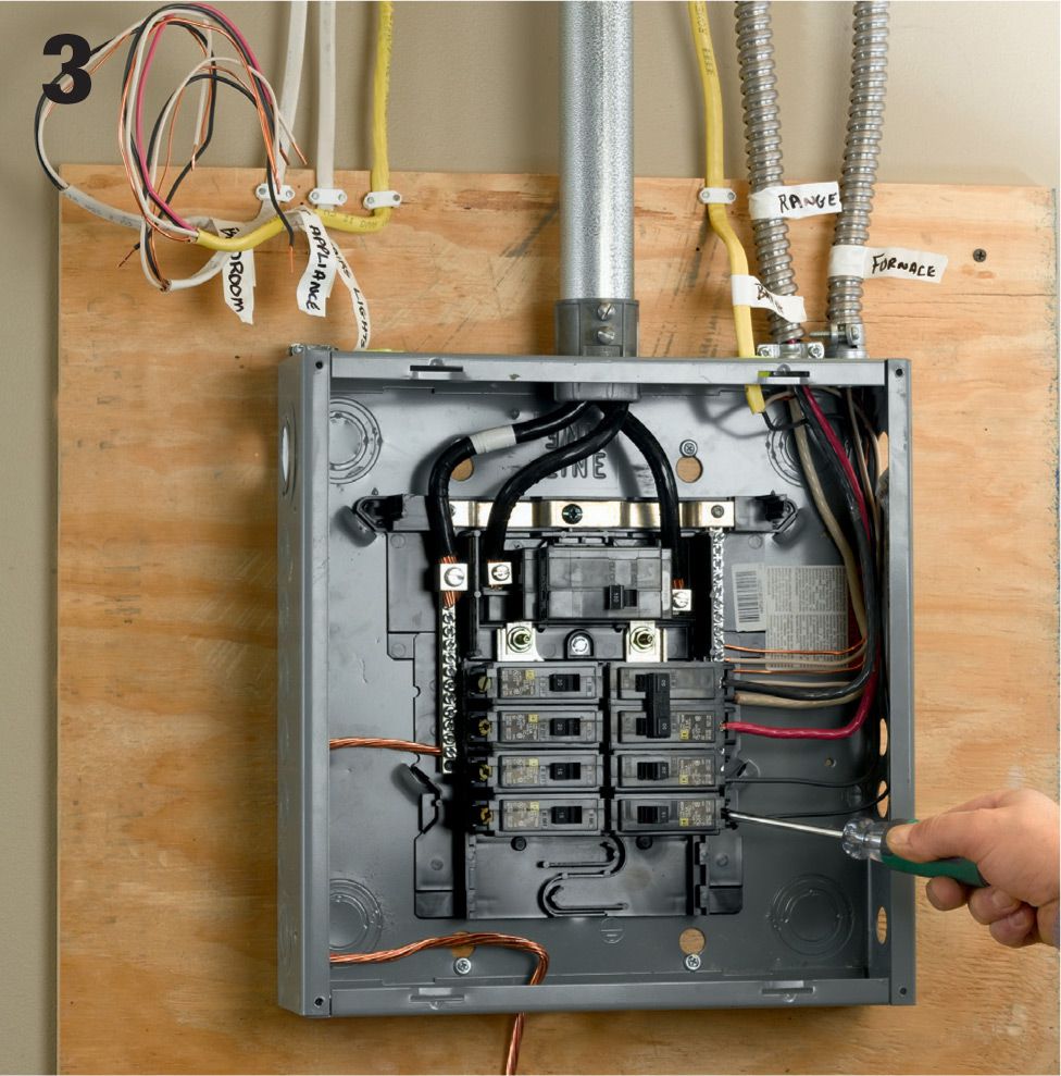
Disconnect incoming circuit wires from breakers, grounding bar, and neutral bus bar. Also disconnect cable clamps at the knockouts on the panel box. Retract all circuit wires from the service panel and coil it up neatly, with the labels clearly visible.
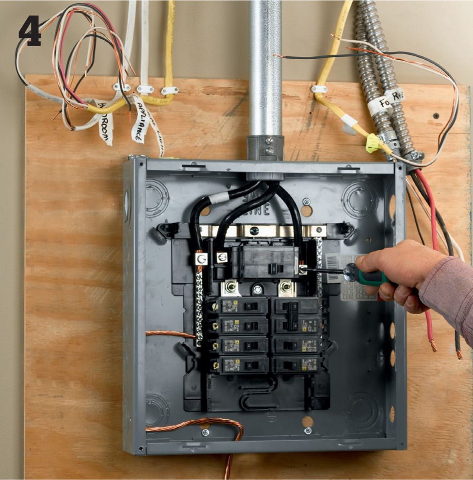
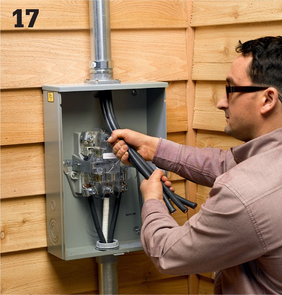
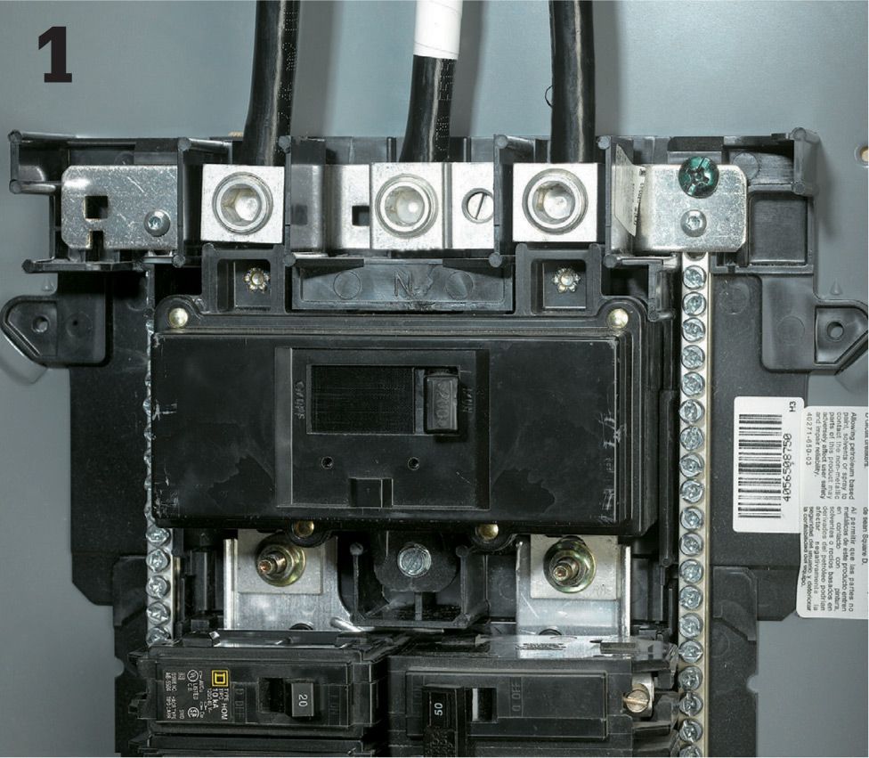
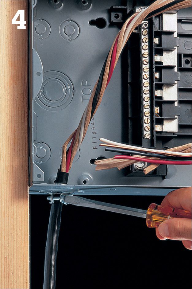
Unscrew the lugs securing the service entry cables at the top of the panel. For 240-volt service you will find two heavy-gauge SE cables, probably with black sheathing. Each cable carries 120 volts of electricity. A neutral service cable, usually of smaller gauge than the SE cables, will be attached to the neutral bus bar. This cable returns current to the source.
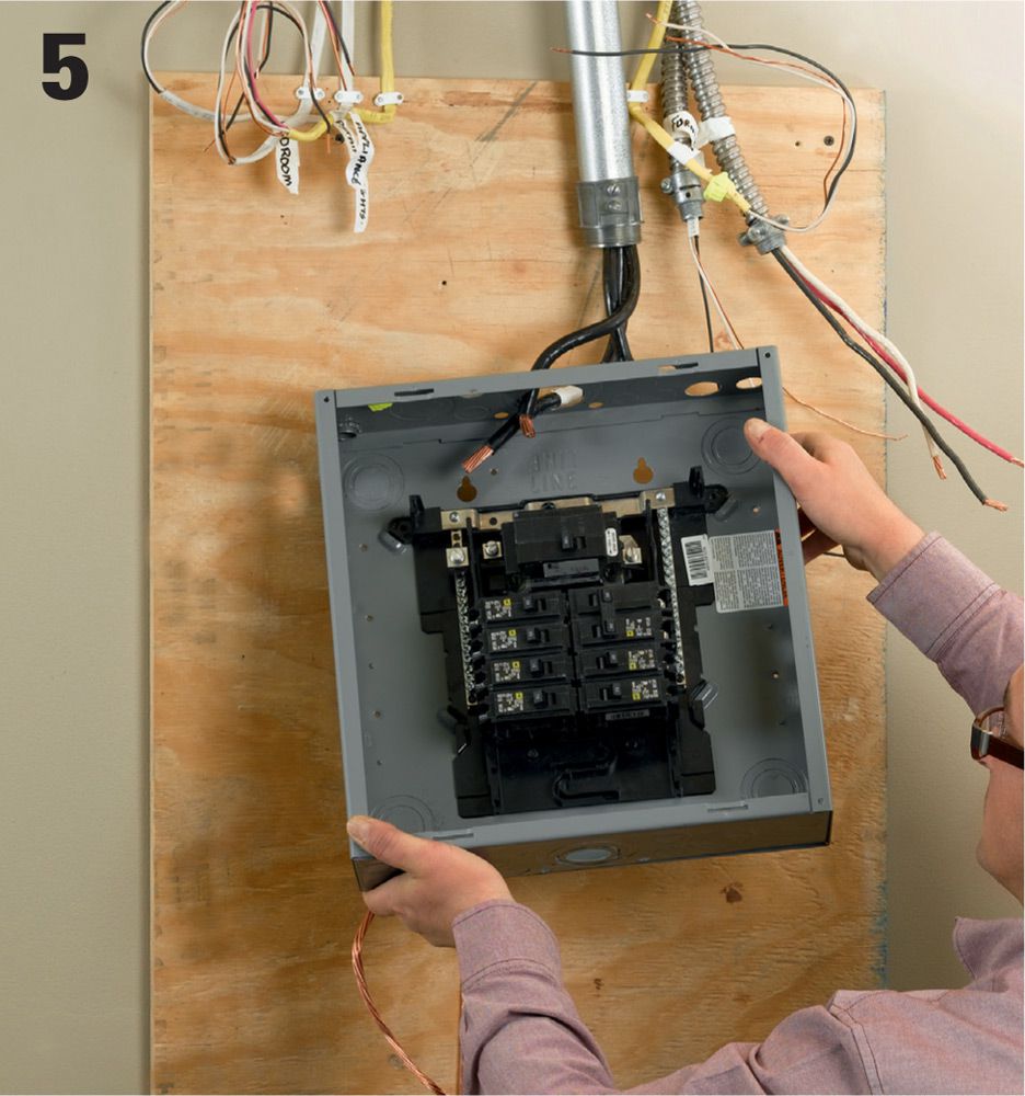
Remove the old service panel box. Boxes are rated for a maximum current capacity; and if you are upgrading, the components in the old box will be undersized for the new service levels. The new box will have a greater number of circuit slots as well.
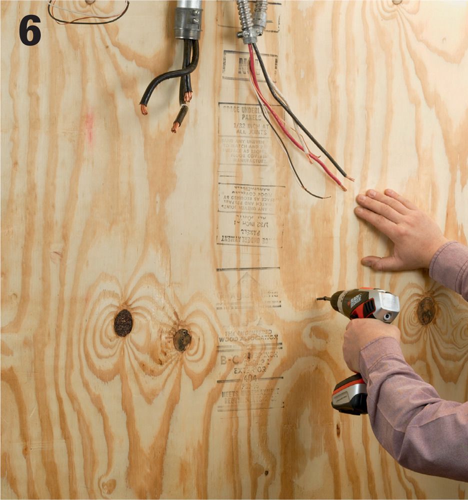
Replace the old panel backer board with a larger board in the installation area (see sidebar, page 174). A piece of 3/4" plywood is typical. Make sure the board is well secured at wall framing members.
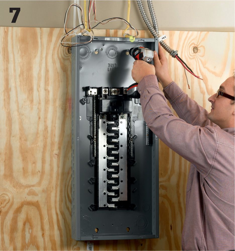
Attach the new service panel box to the backer board, making sure that at least two screws are driven through the backer and into wall studs. Drill clearance holes in the back of the box at stud locations if necessary. Use roundhead screws that do not have tapered shanks so the screwhead seats flat against the panel.
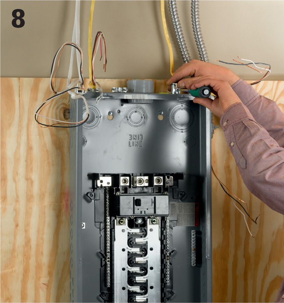
Attach properly sized cable clamps to the box at the knockout holes. Install one cable per knockout in this type of installation and plan carefully to avoid removing knockouts that you do not need to remove (if you do make a mistake, you can fill the knockout hole with a plug).
Splicing in the Box ![]()
Some wiring codes allow you to make splices inside the panel box if the circuit wire is too short. Use the correct wire cap and wind electrical tape over the conductors where they enter the cap. If your municipality does not allow splices in the panel box, you’ll have to rectify a short cable by splicing it in a junction box before it reaches the panel and then replacing the cable with a longer section for the end of the run. Make sure each circuit line has at least 12" of slack.
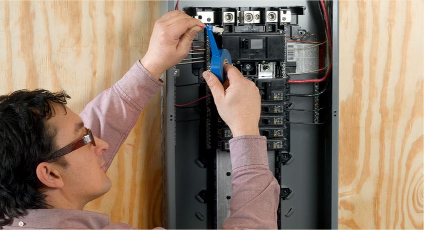
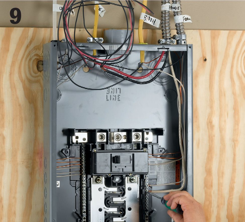
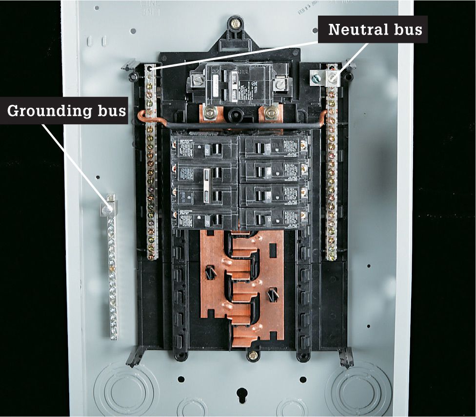
Attach the white neutral from each circuit cable to the neutral bus bar. Most panels have a preinstalled neutral bus bar, but in some cases you may need to purchase the bar separately and attach it to the panel back. The panel should also have a separate grounding bar that you also may need to purchase separately. Attach the grounds as well.
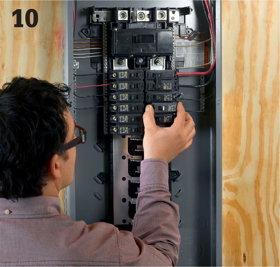
Attach the hot lead wire to the terminal on the circuit breaker, and then snap the breaker into an empty slot. When loading slots, start at the top of the panel and work your way downward. It is important that you balance the circuits as you go to equalize the amperage. For example, do not install all the 15-amp circuits on one side and all the 20-amp circuits on the other.
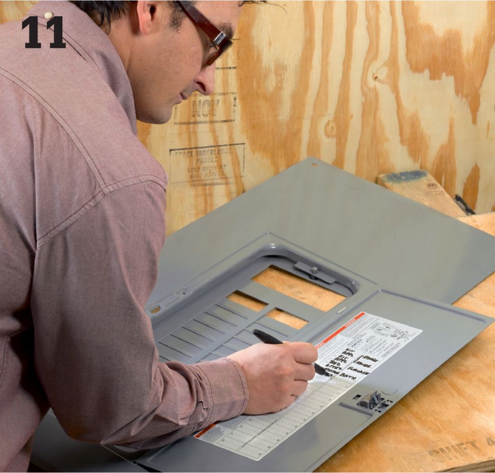
Create an accurate circuit index and affix it to the inside of the service panel door. List all loads that are on the circuit as well as the amperage. Once you have restored power to the new service panel (see step 18), test out each circuit to make sure you don’t have any surprises. With the main breakers on, shut off all individual circuit breakers, and then flip each one on by itself. Walk through your house and test every switch and receptacle to confirm the loads on that circuit.
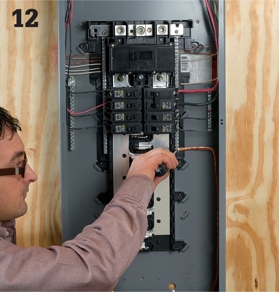
Install grounding conductors (see pages 180 to 185). Local codes are very specific about how the grounding and bonding needs to be accomplished. For example, some require multiple rods driven at least 6 ft. apart. Discuss your grounding requirements thoroughly with your inspector or an electrician before making your plan.
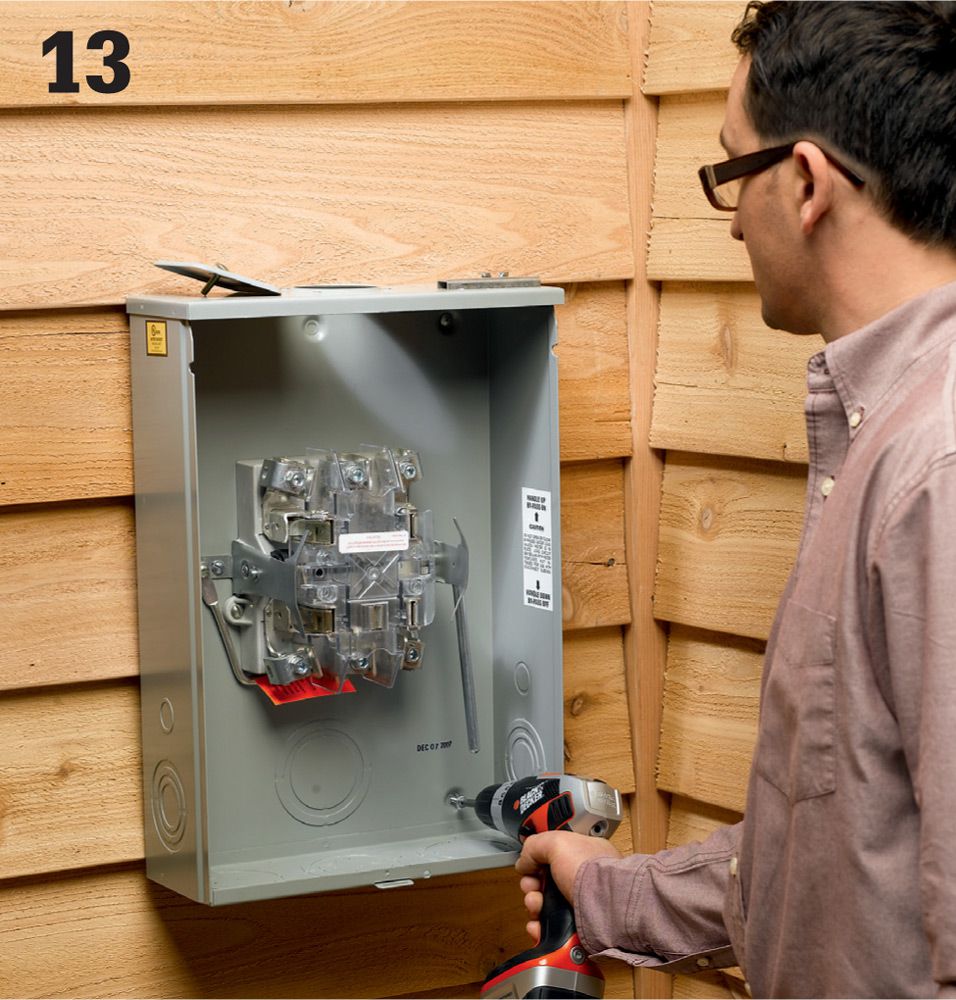
Replace the old meter base (have the utility company remove the meter when they shut off power to the house, step 1). Remove the old meter base, also called a socket, and install a new base that’s rated for the amperage of your new power service. Here, a 200-amp bypass meter base is being installed.
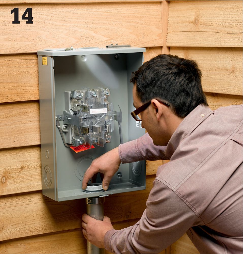
Update the conduit that runs from your house to the bottom of the meter base. This should be 2" rigid conduit in good repair. Attach the conduit to the base and wall with the correct fittings. Rigid metal conduit is a good option, but Schedule 80 PVC is probably the best choice for housing the service entrance wires.
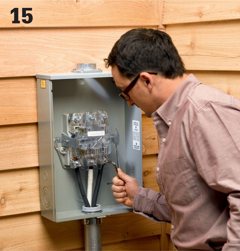
Install new service entrance wires. Each wire carries 120 volts from the meter to the service wire lugs at the top of your service panel. Code is very specific about how these connections are made. In most cases, you’ll need to tighten the terminal nuts with a specific amount of torque that requires a torque wrench to measure. Also attach the sheathed neutral wire to the neutral/grounding lug.
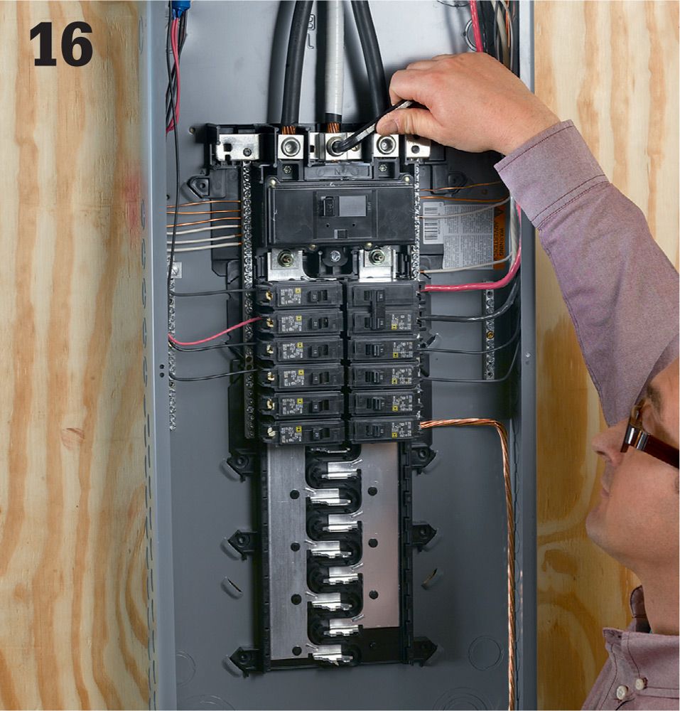
Attach the se wires to the lugs connected to the main breakers at the top of your service entry panel. Do not remove too much insulation on the wires—leaving the wires exposed is a safety hazard. The neutral service entry wire is attached either directly to the neutral bus bar or to a metal bridge that is connected to the neutral bonding bus bar. Install the green grounding screw provided with the panel.
Install service entrance wires from the meter to the weatherhead, where the connections to the service drop wires are made. Only an agent for your public utility company may make the hookup at the weatherhead.
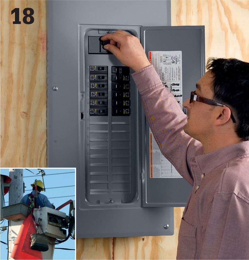
Have the panel and all connections inspected and approved by your local building department, and then contact the public utility company to make the connections at the power drop. Once the connections are made, turn the main breakers on and test all circuits.
Tall Mast, Short Roof ![]()
The service drop must occur at least 10 ft. above ground level, and as much as 14 ft. in some cases. Occasionally, this means that you must run the conduit for the service mast up through the eave of your roof and seal the roof penetration with a boot.
![]() Grounding & Bonding a Wiring System
Grounding & Bonding a Wiring System
All home electrical systems must be bonded and grounded according to code standards. This entails two tasks: the metal water and gas pipes must be connected electrically to create a continuous low resistance path back to the main electrical panel; and the main electrical panel must be grounded to a grounding electrode such as a ground rod or rods driven into the earth near the foundation of your house. Although the piping system is bonded to the ground through your main electrical service panel, the panel grounding and the piping bonding are unrelated when it comes to function. The grounding wire that runs from your electrical panel to grounding electrode helps even out voltage increases that often occur because of lightning and other causes. The wires that bond your metal piping are preventative, and they only become important in the unlikely event that an electrical conductor energizes the pipe. In that case, correct bonding of the piping system will ensure that the current does not remain in the system, where it could electrocute anyone who touches a part of the system, such as a faucet handle. Bonding is done relatively efficiently at the water heater, as the gas piping and water piping generally there.
Gas pipe in older homes is usually steel or copper. The bonding connection point for these pipes can be at any accessible location, such as at the water heater or at the gas meter. Gas pipe in some new homes is a flexible material called corrugated stainless steel tubing (CSST). The bonding point for CSST must be at the first piece of steel or copper pipe where the gas service enters the home. This is because lightning can blow holes in CSST, causing a gas leak.
Tools & Materials ![]()
Hammer
Straight edge screwdriver
Drill
1/2" drill bit
A length of ground wire
Some wire staples
3 pipe ground clamps
Eye and ear protection
Work gloves
Grounding rods
5-lb. maul
Caulk
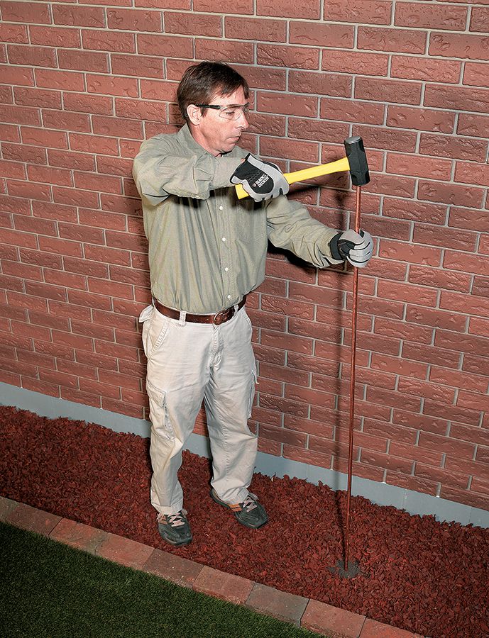
A pair of 8-ft.-long metal ground rods are driven into the earth next to your house to provide a path to ground for your home wiring system.
![]() How to Bond Metallic Piping
How to Bond Metallic Piping
Determine the amperage rating of your electrical service by looking at your main breakers. The system amperage (usually 100 or 200 amps) determines the required gauge of the bonding wire you need. #4 copper wire is sufficient for service not exceeding 200 amps. Smaller, less expensive copper wire is allowed for services between 100 and 175 amps. Check with your electrical inspector if you want to use wire smaller than #4.
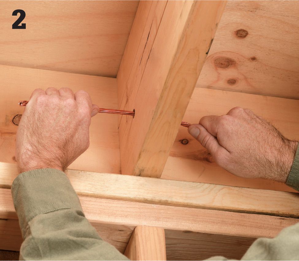
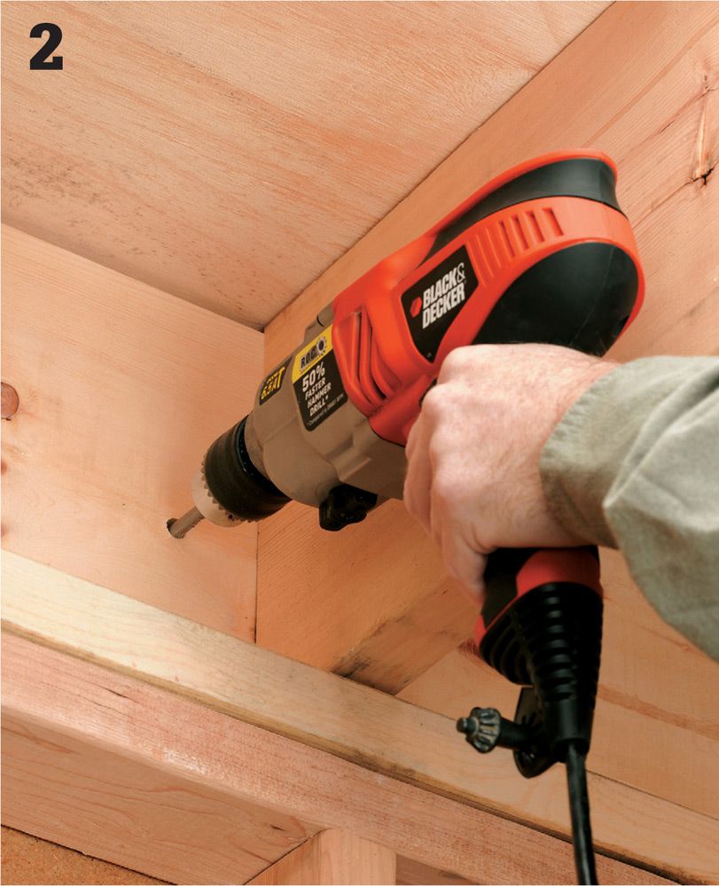
Run the bonding wire from a point near your water heater (a convenient spot if you have a gas-fueled water heater) to an exit point where the wire can be bonded to the grounding wire that leads to the exterior grounding electrodes. This is frequently done at the service panel. Run this wire as you would any other cable, leaving approximately 6 to 8 ft. of wire at the water heater. If you are running this wire through the ceiling joists, drill a 1/2" hole as close to the center as possible to not weaken the joist. Staple the wire every 2 ft. if running it parallel to the joists.
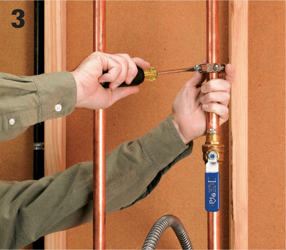
Install pipe ground clamps on each pipe (hot water supply, cold water supply, gas), roughly a foot above the water heater. Do not install clamps near a union or elbow because the tightening of the clamps could break or weaken soldered joints. Also make sure the pipes are free and clear of any paint, rust, or any other contaminant that may inhibit a good clean connection. Do not overtighten the clamps. Use clamps that are compatible with the pipe so that corrosion will not occur. Use copper or brass clamps on copper pipe. Use brass or steel clamps on steel pipe.
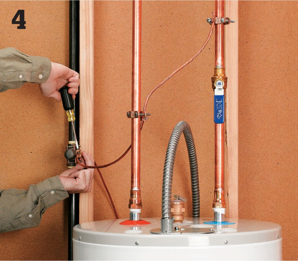
Route the ground wire through each clamp wire hole and then tighten the clamps onto the wire. Do not cut or splice the wire: The same wire should run through all clamps.
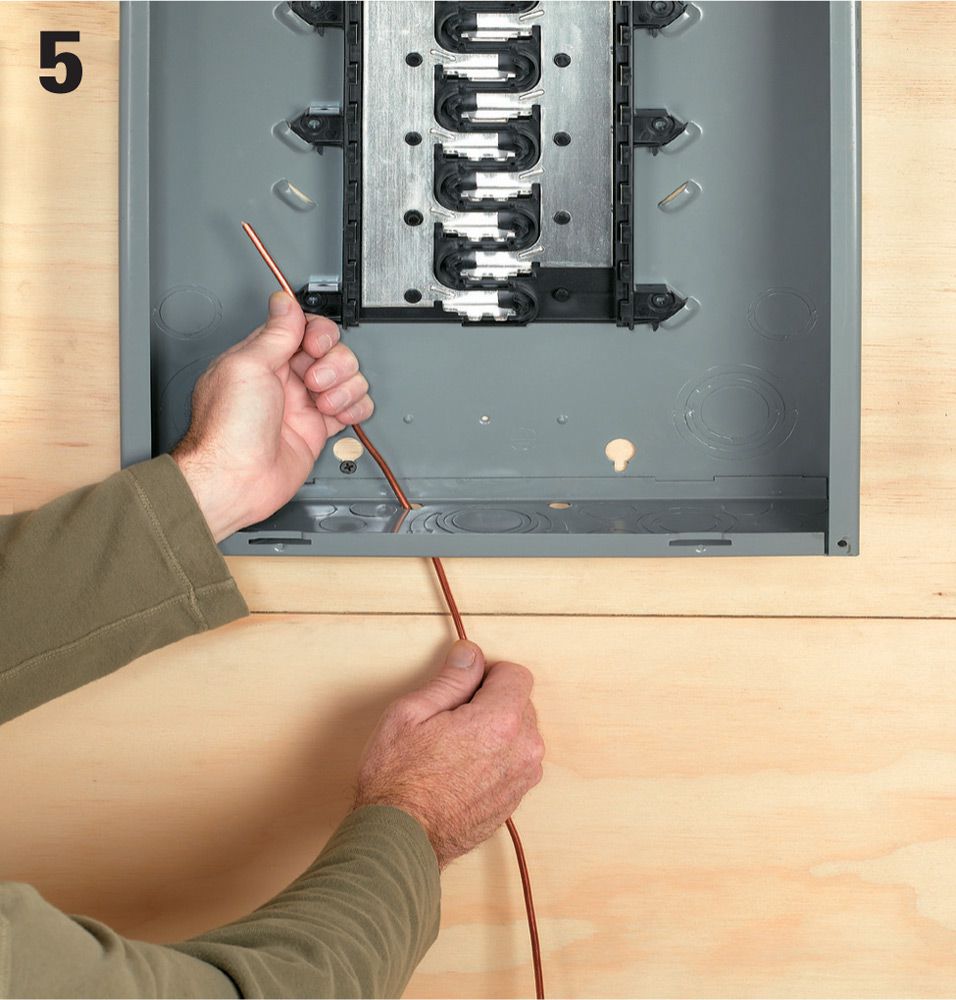
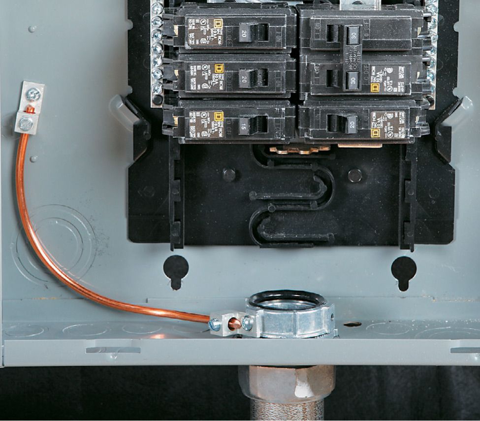
At the panel, turn off the main breaker. Open the cover by removing the screws, and set the cover aside. Route the ground wire through a small 3/8" hole provided towards the rear of the panel on the top or bottom. You will usually have to knock the plug out of this hole by placing a screwdriver on it from the outside and tapping with a hammer. Make sure the ground wire will not come into contact with the bus bars in the middle of the panel or any of the load terminals on the breakers.
Locate an open hole on your ground and neutral bus and insert the ground wire. These holes are large enough to accommodate up to a #4 awg wire, but it may be difficult at times. If you’re having trouble pushing the wire in, trim a little wire off the end and try with a clean cut piece. Secure the set screw at the lug. Replace the panel cover and turn the main breaker back on.
![]() Tips for Grounding the Main Service Panel
Tips for Grounding the Main Service Panel
The neutral and grounding wires should not be connected to the same bus in most subpanels. The grounding bus should be bonded to the subpanel cabinet. The neutral bus should not be bonded to the subpanel cabinet.
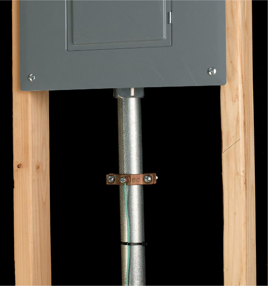
Metallic conduit must be physically and electrically connected to panel cabinets. A bonding bushing may be required in some cases, where not all of a knockout is removed.
![]() Ground Rod installation
Ground Rod installation
The ground rod is an essential part of the grounding system. Its primary function is to create a path to ground for electrical current, such as lightning, line surges, and unintentional contact with high voltage lines. If you upgrade your electrical service you likely will need to upgrade your grounding wire and rods to meet code.
Note: Different municipalities have different requirements for grounding, so be sure to check with the AHJ (Authority Having Jurisdiction) first before attempting to do this yourself.
Call before you dig! Make sure the area where you will be installing the ground rods is free and clear from any underground utilities.
Exercise Your Breakers ![]()
Your breakers (including the main) should be “exercised” once a year to ensure proper mechanical function. Simply turn them off and then back on. A convenient time to perform the exercise is at daylight savings time, when you’ll need to reset all of your clocks anyway.
![]() How to Install a Grounding Electrode System
How to Install a Grounding Electrode System
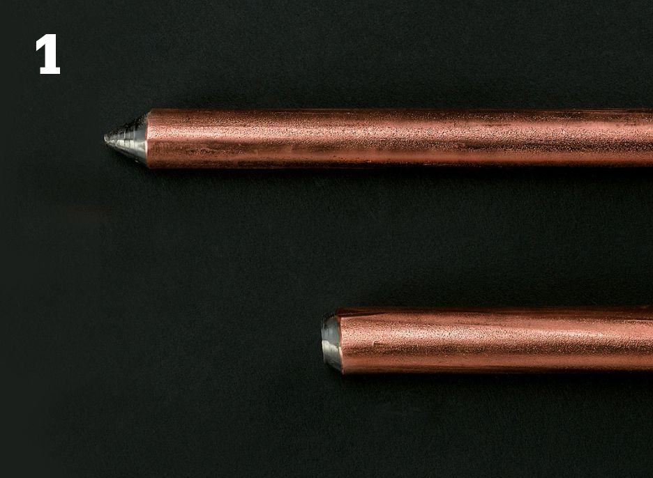
Begin by purchasing two copper-coated steel ground rods 5/8" diameter by 8' long. Grounding rods have a driving point on one end and a striking face on the other end.
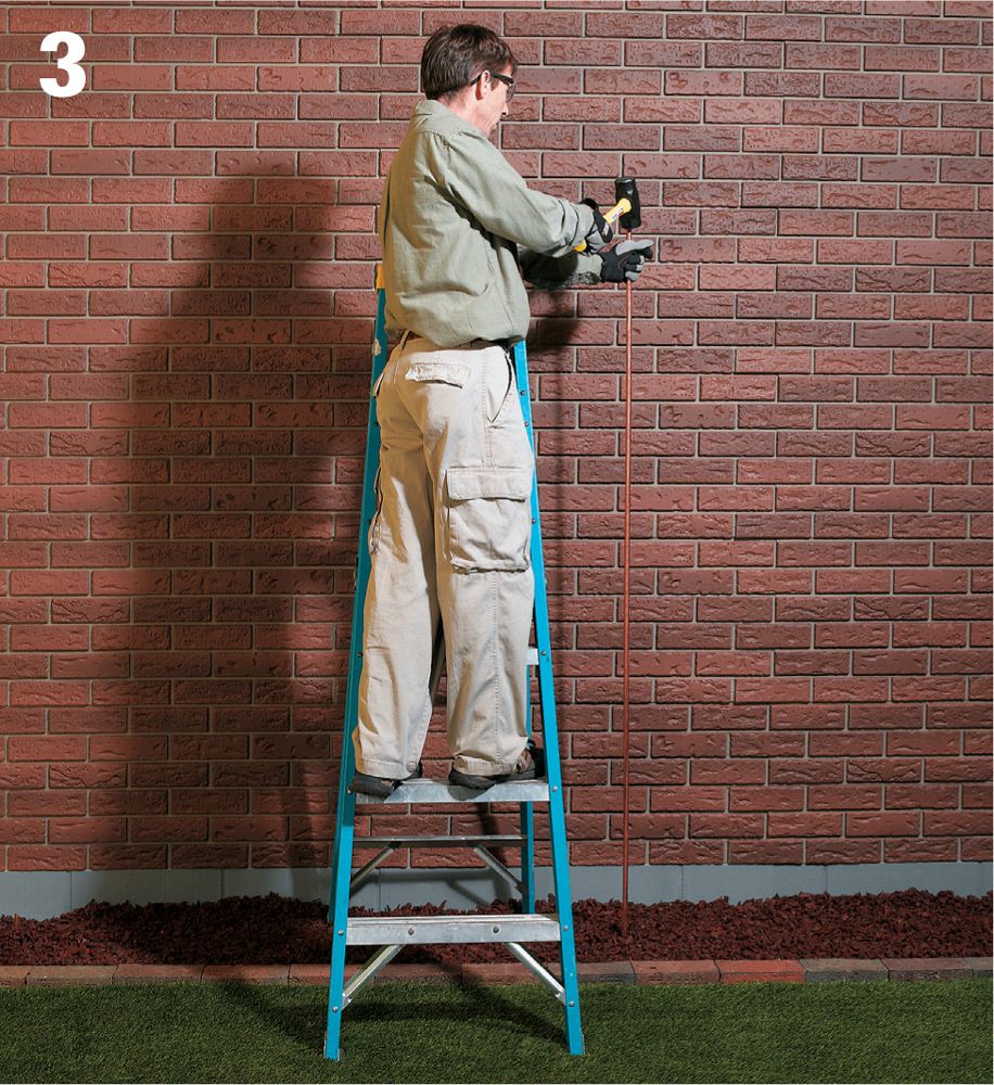
Drill a 5/16" hole in the rim joist of your house, as close as practical to the main service panel to the outside of the house above the ground level at least 6".
About a foot from the foundation of the house, pound one ground rod into the earth with a five-pound maul. If you encounter a rock or other obstruction, you can pound the ground rod at an angle as long as it does not exceed 45°. Drive until only 3" or 4" of the rod is above ground. Measure at least 6 ft. from the first ground rod and pound in another one.
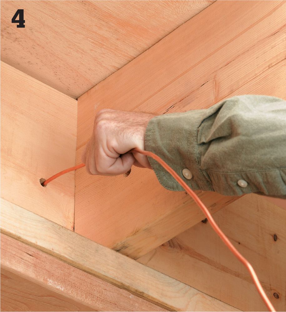
Run uninsulated #4 copper wire from the ground bus in your main service panel through the hole in the rim joist and to the exterior of the house, leaving enough wire to connect the two ground rods together.

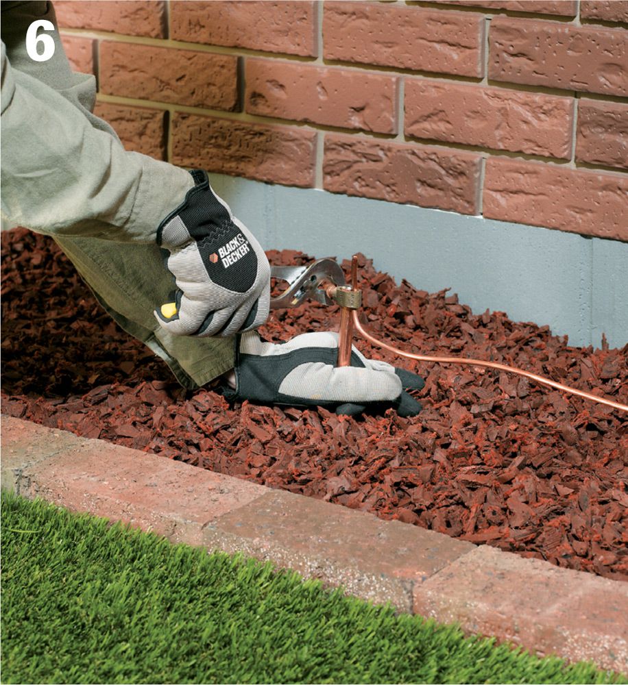
Using a brass clamp commonly referred to as an acorn, connect the wire to the first ground rod, pulling the wire taut so no slack exists. Continue pulling the wire to reach the second grounding rod, creating a continuous connection.
Connect the second ground rod with another acorn to the uncut grounding wire previously pulled through the first acorn. Trim the excess wire.
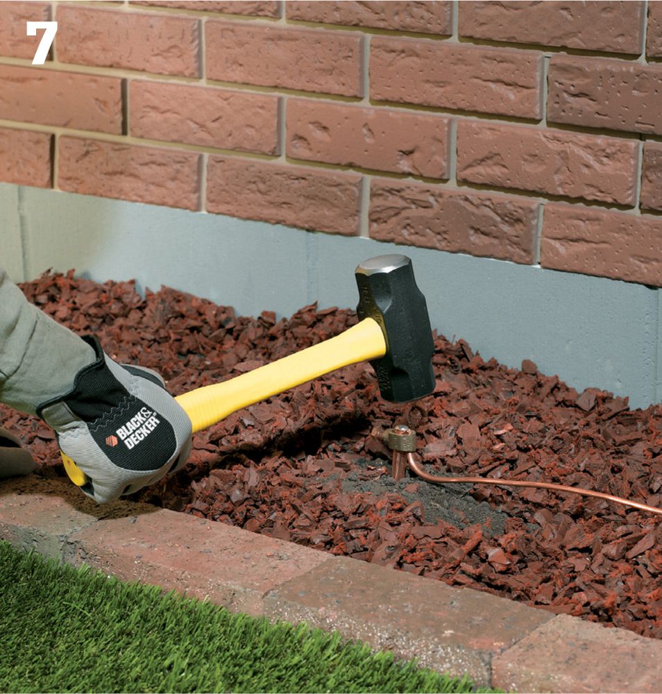
Dig out a few inches around each rod to create clearance for the five-pound maul. Creating a shallow trench beneath the grounding wire between the rods is also a good idea. Drive each rod with the maul until the top of the rod is a few inches below grade.
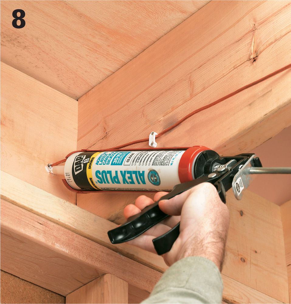
Inject caulk into the hole in the rim joist on both the interior and exterior side.
![]() Tips for Grounding
Tips for Grounding
A listed metal strap may be used to ground indoor communication wires such as telephone and cable TV if an intersystem bonding terminal is not available.
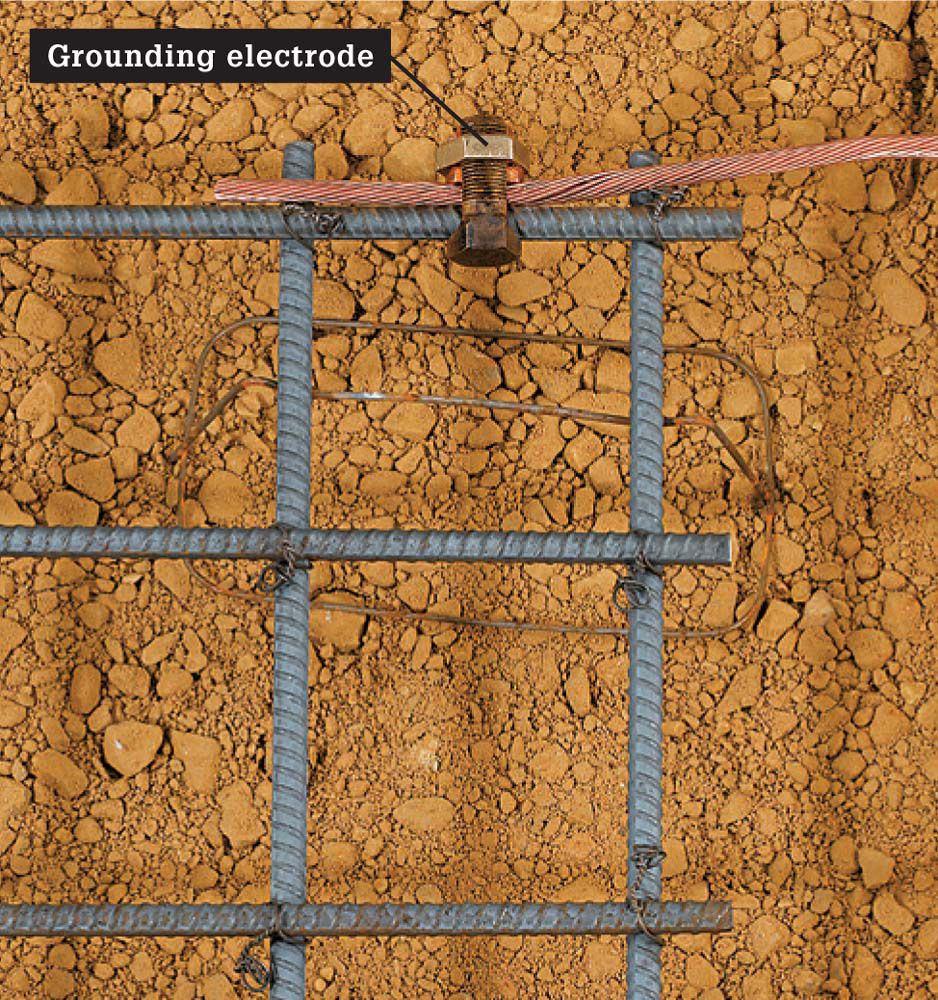
A piece of reinforcing bar encased in a concrete footing is a common grounding electrode in new construction. Called an ufer, the electrode must be No. 4 or larger rebar and at least 20 ft. long. (Shown prior to pouring concrete.)
![]() Subpanels
Subpanels
Install circuit breaker subpanels if the main circuit breaker panel does not have enough open breaker slots for the new circuits you are planning. Subpanels serve as a second distribution center for connecting circuits. They receive power from a double-pole circuit breaker you install in the main circuit breaker panel.
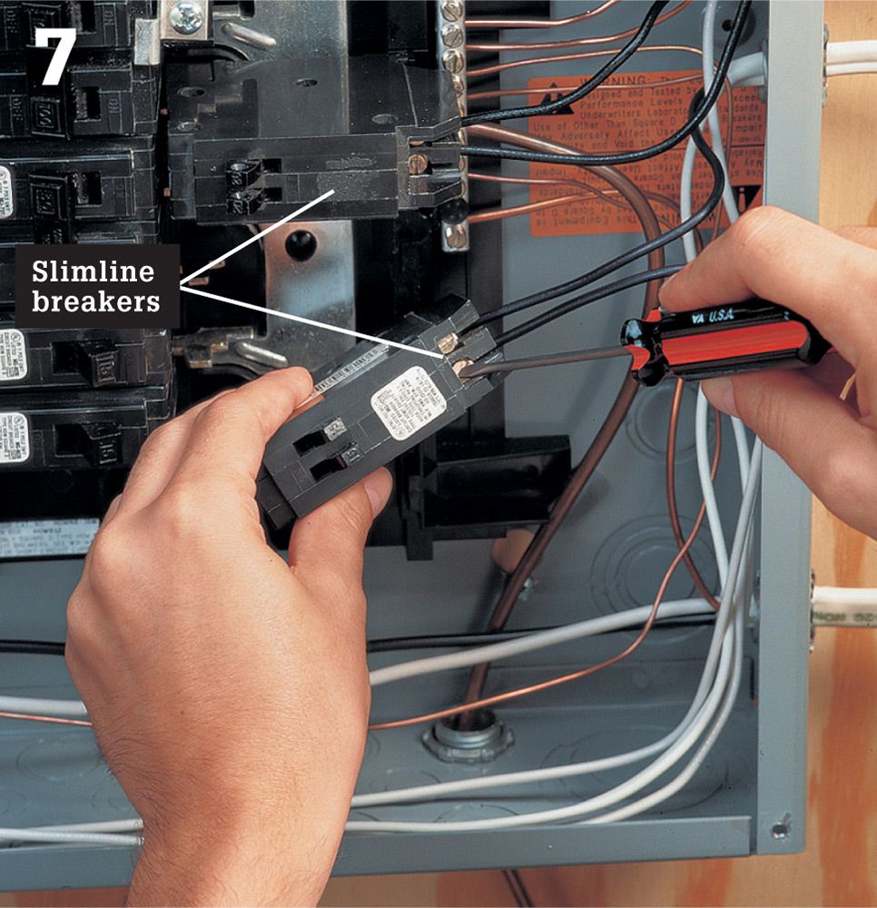
If the main service panel is so full that there is no room for the double-pole subpanel breaker, you can reconnect some of the existing 120-volt circuits to special slimline breakers (photos below).
Plan your subpanel installation carefully, making sure your electrical service supplies enough power to support the extra load of the new subpanel circuits. Assuming your main service is adequate, consider installing an oversized subpanel breaker in the main panel to provide enough extra amps to meet the needs of future wiring projects.
Also consider the physical size of the subpanel, and choose one that has enough extra slots to hold circuits you may want to install later. The smallest panels have room for up to six single-pole breakers (or three double-pole breakers), while the largest models can hold 20 single-pole breakers or more.
Subpanels often are mounted near the main circuit breaker panel. Or, for convenience, they can be installed close to the areas they serve, such as in a new room addition or a garage. In a finished room, a subpanel can be painted or housed in a decorative cabinet so it is less of a visual distraction. If it is covered, make sure the subpanel is easily accessible and clearly identified.
Tools & Materials ![]()
Hammer
Screwdriver
Circuit tester
Cable ripper
Combination tool
Screws
Cable clamps
Three-wire NM cable
Cable staples
Double-pole circuit breaker
Circuit breaker subpanel
Slimline circuit breakers
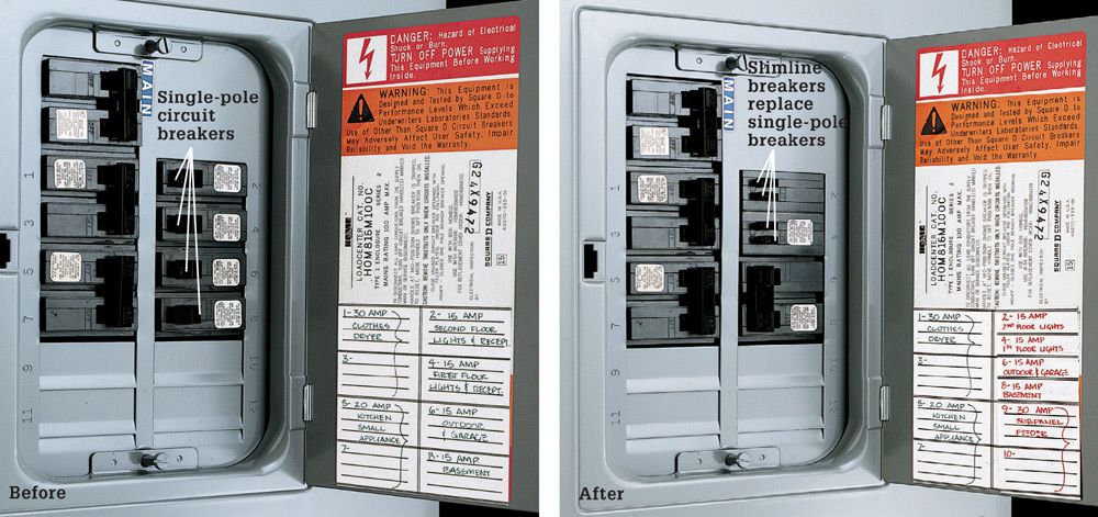
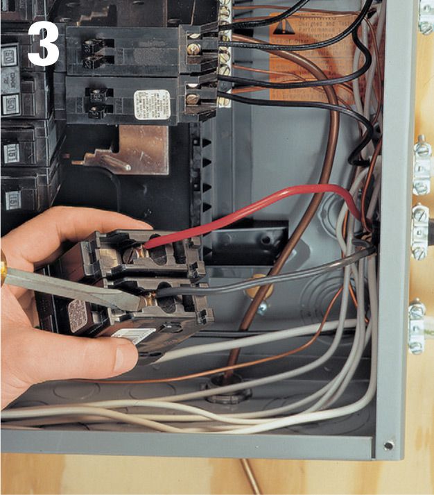
To conserve space in a service panel, you can replace single-pole breakers with slimline breakers. Slimline breakers take up half the space of standard breakers, allowing you to fit two circuits into one single slot on the service panel. In the service panel shown above, four single-pole 120-volt breakers were replaced with slimline breakers to provide the double opening needed for a 30-amp, 240-volt subpanel feeder breaker. Use slimline breakers (if your municipality allows them) with the same amp rating as the standard single-pole breakers you are removing, and make sure they are approved for use in your panel. If your municipality and panel allow slimline breakers, there may be restrictions on the quantity and location where they may be installed on the panel.
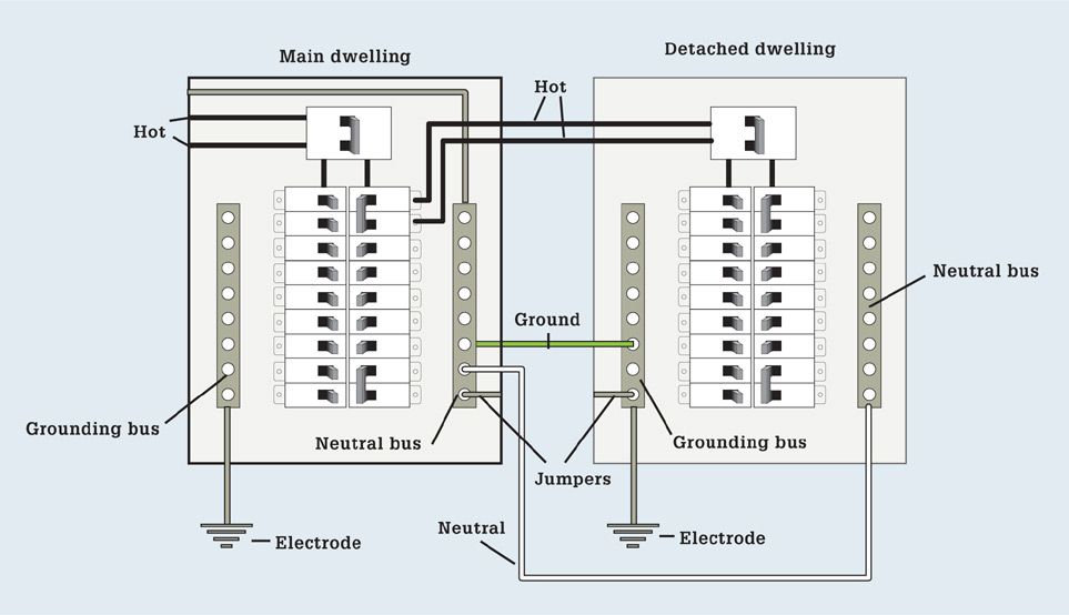
Wiring diagram for wiring a feeder from the main service panel to a subpanel in a separate building.
![]() How to Install a Subpanel
How to Install a Subpanel
Subpanels are subject to the same installation and clearance rules as service panels. The subpanel can be mounted to the sides of studs or to plywood attached between two studs. The panel shown here extends 1/2" past the face of studs so it will be flush with the finished wall surface.

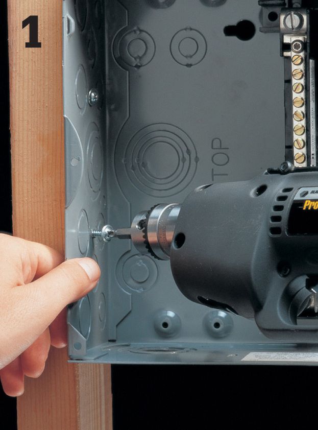
Open a knockout in the subpanel using a screwdriver and hammer. Run the feeder cable from the main circuit breaker panel to the subpanel, leaving about 2 ft. of excess cable at each end. See page 40 if you need to run the cable through finished walls.
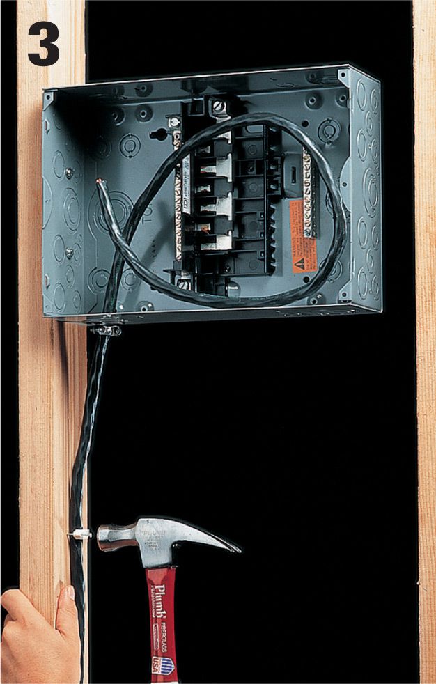
Attach a cable clamp to the knockout in the subpanel. Insert the cable into the subpanel, and then anchor it to framing members within 8" of each panel and every 54" thereafter.
Strip away outer sheathing from the feeder cable using a cable ripper. Leave at least 1/4" of sheathing extending into the subpanel. Tighten the cable clamp screws so the cable is held securely, but not so tightly that the wire sheathing is crushed.
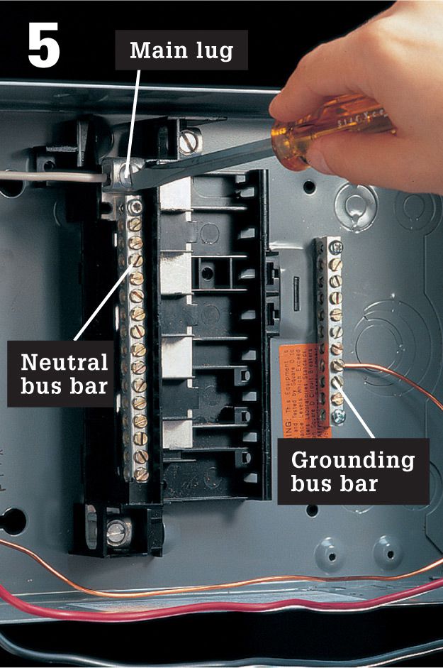
Strip 1/2" of insulation from the white neutral feeder wire, and attach it to the main lug on the subpanel neutral bus bar. Connect the grounding wire to a setscrew terminal on the grounding bus bar. Fold excess wire around the inside edge of the subpanel.
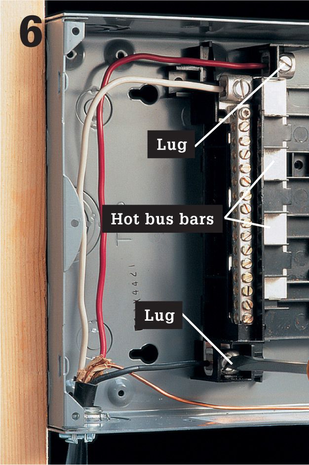
Strip away 1/2" of insulation from the red and the black feeder wires. Attach one wire to the main lug on each of the hot bus bars. Fold excess wire around the inside edge of the subpanel.
At the main circuit breaker panel, shut off the main circuit breaker, and then remove the coverplate and test for power (page 80). If necessary, make room for the double-pole feeder breaker by removing single-pole breakers and reconnecting the wires to slimline circuit breakers. Open a knockout for the feeder cable using a hammer and screwdriver. Note: some panels do not allow slimline breakers and some restrict where slimline breakers can be installed. Read the instructions on the panel cover.
Strip away the outer sheathing from the feeder cable so that at least 1/4" of sheathing will reach into the main service panel. Attach a cable clamp to the cable, and then insert the cable into the knockout, and anchor it by threading a locknut onto the clamp. Tighten the locknut by driving a screwdriver against the lugs. Tighten the clamp screws so the cable is held securely, but not so tightly that the cable sheathing is crushed.
Bend the bare copper wire from the feeder cable around the inside edge of the main circuit breaker panel, and connect it to one of the setscrew terminals on the grounding bus bar.
Strip away 1/2" of insulation from the white feeder wire. Attach the wire to one of the setscrew terminals on the neutral bus bar. Fold excess wire around the inside edge of the service panel.
Strip 1/2" of insulation from the red and the black feeder wires. Attach one wire to each of the setscrew terminals on the double-pole feeder breaker. Note: If your subpanel arrived with a preinstalled grounding screw in the panel back, remove and discard it.
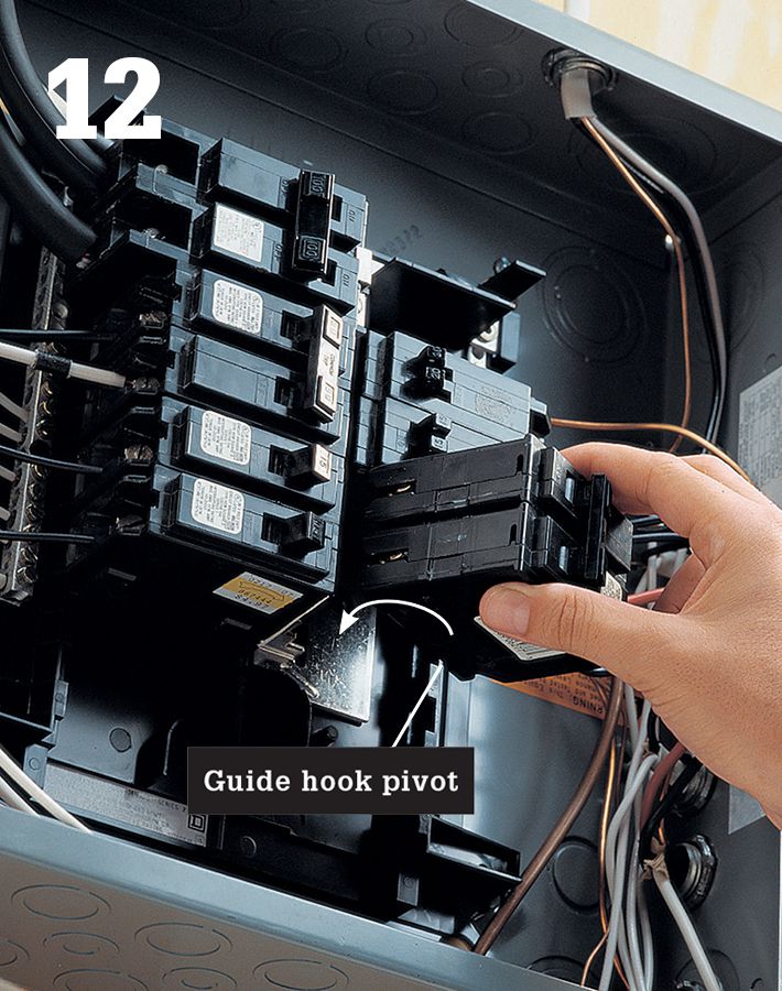
Hook the end of the feeder circuit breaker over the guide hooks on the panel, and then push the other end forward until the breaker snaps onto the hot bus bars (follow manufacturer’s directions). Fold excess wire around the inside edge of the circuit breaker panel.
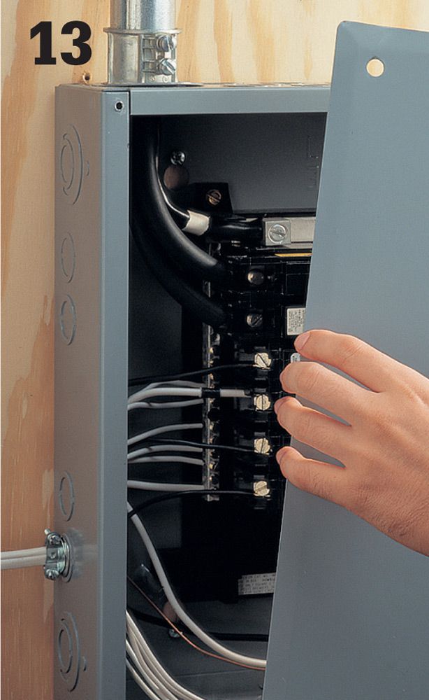
If necessary, open two tabs where the double-pole feeder breaker will fit, and then reattach the cover plate. Label the feeder breaker on the circuit index. Turn the main breaker on, but leave the feeder breaker off until all subpanel circuits have been connected and inspected.
![]() 120/240-Volt Dryer Receptacles
120/240-Volt Dryer Receptacles
Many dryers require both 120- and 240-volt power. If you are installing this type of electric dryer, you will need to install a 30-amp, 120/240-volt receptacle that feeds from a dedicated 30-amp double-pole breaker in your service panel. Verify your dryer’s electric requirements before wiring a new receptacle.
Begin the installation by identifying a location for the dryer receptacle. Run 10/3 NM cable from the service panel to the new receptacle. If you are mounting the dryer receptacle box on an unfinished masonry wall, run the THNN wire in conduit and secure the box and conduit with masonry screws. If you are mounting the receptacle box in finished drywall, cut a hole, fish the cable through, and mount the receptacle in the wall opening.
Tools & Materials ![]()
Combination tool
Drill
Circuit tester
Hammer
Screwdriver
30-amp double-pole breaker
30-amp 120/240-volt dryer receptacle
10/3 NM cable or 10-gauge THHN/THWN
Receptacle box
Conduit (for masonry walls)
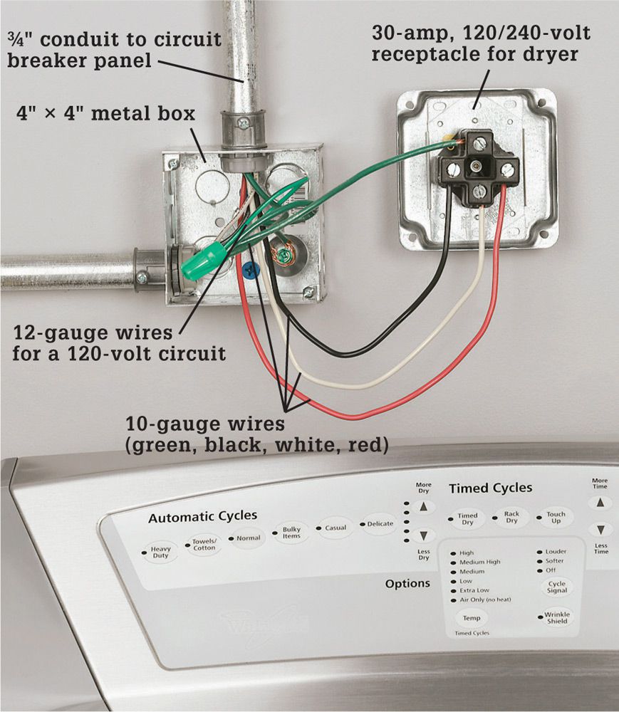
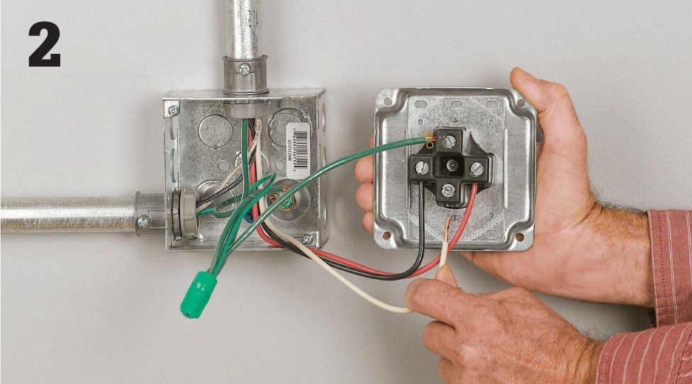
A 240-volt installation is no more complicated than wiring a single-pole breaker and outlet. The main difference is that the dryer circuit’s double-pole breaker is designed to contact both 120-volt bus bars in the service panel. Together these two 120-volt circuits serve the dryer’s heating elements with 240 volts of power. The timer, switches, and other dryer electronics utilize the circuit’s 120-volt power.
![]() How to Install a 120/240-Volt Dryer Receptacle
How to Install a 120/240-Volt Dryer Receptacle
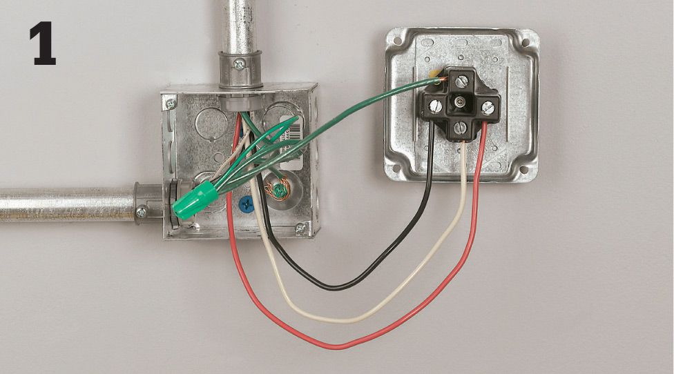
Connect the white neutral wire to the silver neutral screw terminal. Connect each of the black and the red wires to either of the brass screw terminals (the terminals are interchangeable). Connect the green ground wire to the receptacle grounding screw. Attach the cover plate.
With the service panel main breaker shut off, connect the dryer cable to a dedicated 30-amp double-pole breaker. Connect the ground wire to the panel grounding bar. Connect the white neutral wire to the neutral bar. Connect the red and the black wires to the two brass screw terminals on the breaker. Snap the breaker into the bus bar. Attach the panel cover. Turn the breakers on, and test the circuit.
![]() 120/240-Volt Range Receptacles
120/240-Volt Range Receptacles
Many electric ranges require both 120- and 240-volt power. If you are installing this type of electric range, you will need to install a 40- or 50-amp 120/240-volt receptacle that feeds from a dedicated 40- or 50-amp breaker in the service panel. Breaker amperage depends on the amount of current the range draws. Verify requirements before wiring a receptacle.
A range receptacle and breaker installation is no more complicated than wiring a single-pole breaker and outlet. The main difference is that the range circuit’s double-pole breaker is designed to contact both 120-volt bus bars in the service panel. Together these two 120-volt circuits serve the range’s heating elements with 240 volts of power. The timer, switches, and other range electronics utilize the circuit’s 120-volt power.
Modern range receptacles accept a four-prong plug configuration. The cable required is four-conductor cable, containing three insulated wires and one ground. The two hot wires might be black and red (shown below) or black and black with a red stripe. The neutral wire is generally white or gray. The grounding wire is green or bare. The size used for a kitchen range is usually 6/3 grounded NM copper cable. The receptacle itself is generally surface mounted for easier installation (shown below), though flush-mounted units are also available.
Tools & Materials ![]()
Combination tool
Circuit tester
Drill
Hammer
Screwdriver
Drywall saw
Fish tape
Surface-mounted range receptacle
6/3 grounded NM cable
40- or 50-amp double-pole circuit breaker
![]() How to Install a Kitchen Range Receptacle
How to Install a Kitchen Range Receptacle
Turn power off. Identify a location for the surface-mounted range receptacle. Cut a small hole in the wall. Fish the cable from the service panel into the wall opening. Thread the cable into a surface-mounted receptacle and clamp it. Strip insulation from the individual wires.
Wire the receptacle. Connect the bare copper ground wire to the receptacle grounding screw. Connect the white neutral wire to the silver neutral screw terminal. Connect each of the hot (black and red) wires to either of the brass screw terminals (the terminals are interchangeable). Mount the housing on the wall and attach the cover plate.
Wire the cable to a 40- or 50-amp breaker. With the main breaker off, remove the panel cover. Remove a knockout from the panel and feed the cable into the panel. Connect the ground to the grounding bar. Connect the neutral wire from the cable to the neutral bar. Connect the red and the black wires to the two brass screw terminals on the breaker. Snap it into the bus bar. Attach the panel cover. Turn the breakers on and test the circuit.
![]() Ceiling Lights
Ceiling Lights
Ceiling fixtures don’t have any moving parts, and their wiring is very simple, so, other than changing bulbs, you’re likely to get decades of trouble-free service from a fixture. This sounds like a good thing, but it also means that the fixture probably won’t fail and give you an excuse to update a room’s look with a new one. Fortunately you don’t need an excuse. Upgrading a fixture is easy and can make a dramatic impact on a room. You can substantially increase the light in a room by replacing a globe-style fixture with one with separate spot lights, or you can simply install a new fixture that matches the room’s décor. Check the weight rating of the box to which you will attach your fixture. Older boxes may not handle a heavy fixture.
Tools & Materials ![]()
Replacement light fixture
Wire stripper
Voltage sensor
Insulated screwdrivers
Wire connectors
Eye protection
If you are unsure how much weight the existing box can handle, consider changing the box. New light fixture boxes should handle fixtures up to 50 pounds. Support the fixture independently from the box if the fixture weighs more than 50 pounds.
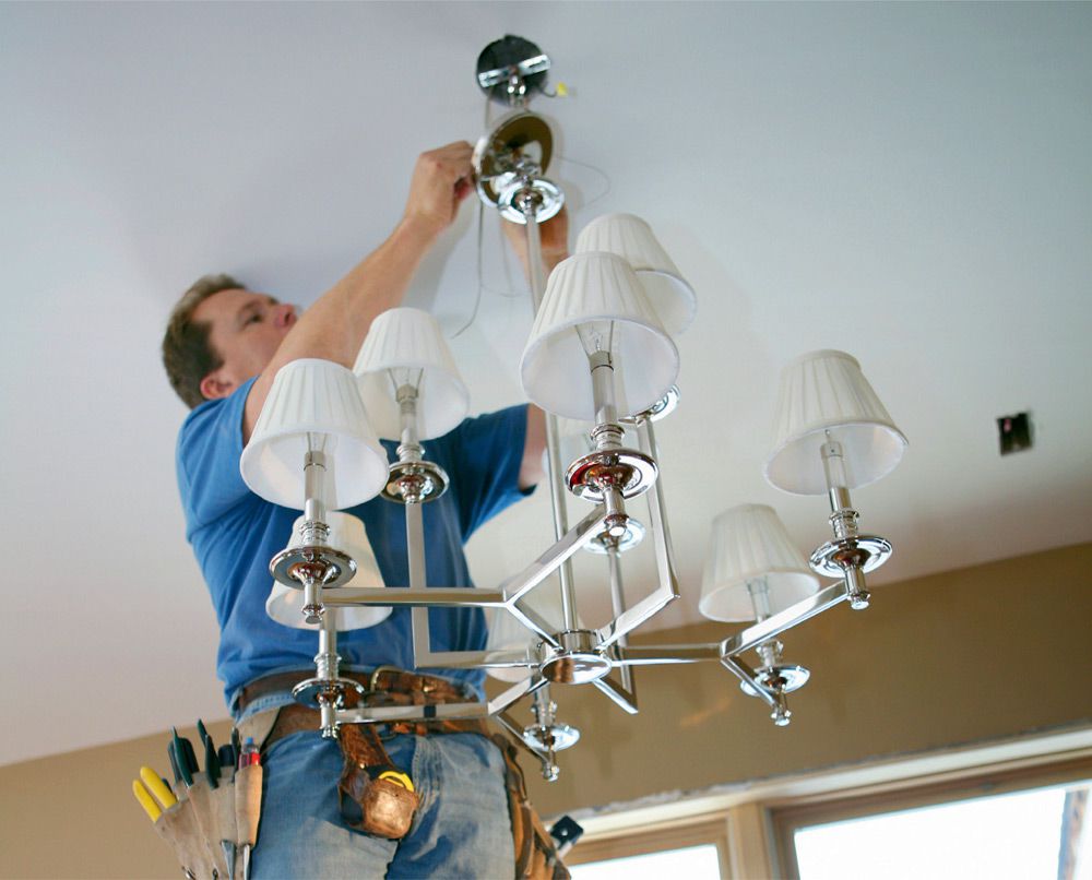
Installing a new ceiling fixture can provide more light to a space, not to mention an aesthetic lift. It’s one of the easiest upgrades you can do.
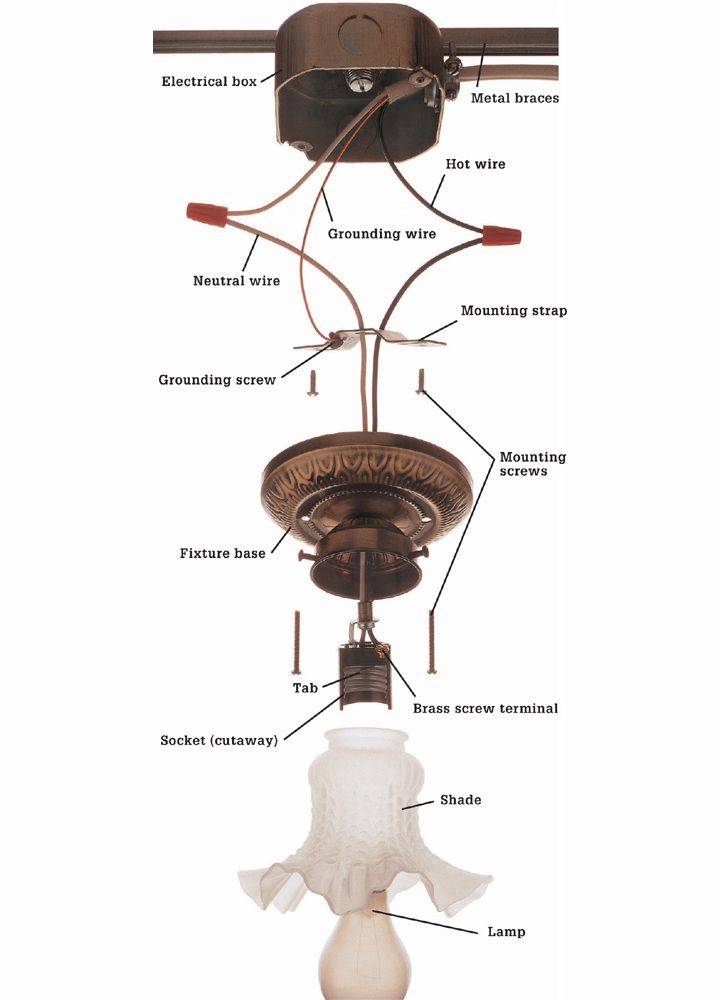
No matter what a ceiling light fixture looks like on the outside, they all attach in basically the same way. An electrical box in the ceiling is fitted with a mounting strap, which holds the fixture in place. The bare wire from the ceiling typically connects to the mounting strap. The two wires coming from the fixture connect to the black and the white wires from the ceiling.
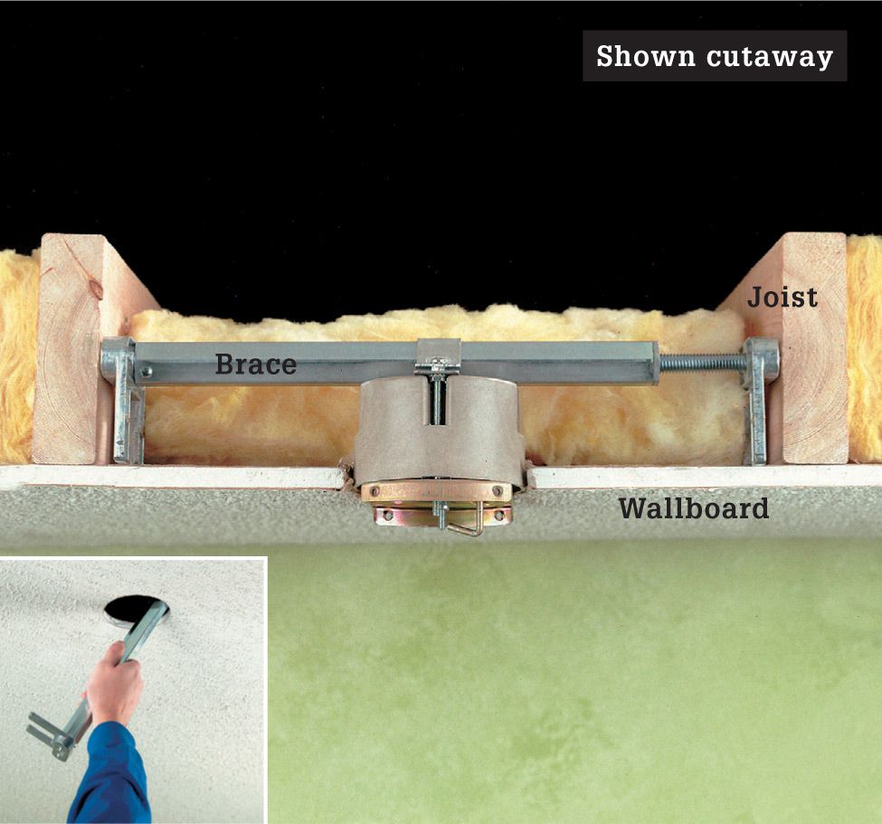
If the new fixture is much heavier than the original fixture, it will require additional bracing in the ceiling to support the electrical box and the fixture. The manufacturer’s instructions should specify the size and type of box. If the ceiling is finished and there is no access from above, you can remove the old box and use an adjustable remodeling brace appropriate for your fixture (shown). The brace fits into a small hole in the ceiling (inset). Once the bracing is in place, install a new electrical box specified for the new fixture.
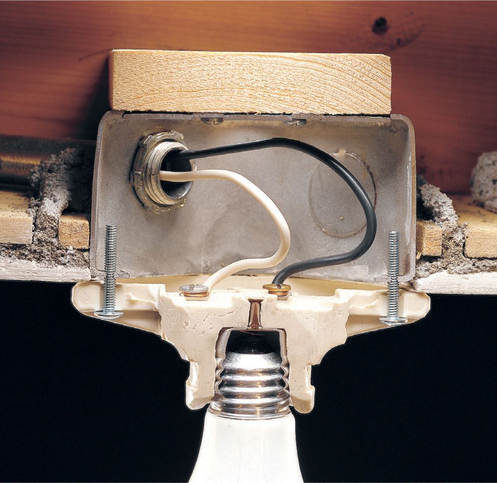
Inexpensive light fixtures have screw terminals mounted directly to the backside of the fixture plate. Often, as seen here, they have no grounding terminal. Some codes do not allow this type of fixture, but even if your hometown does approve them, it is a good idea to replace them with a better quality, safer fixture that is UL-approved.
![]() How to Replace a Ceiling Light
How to Replace a Ceiling Light
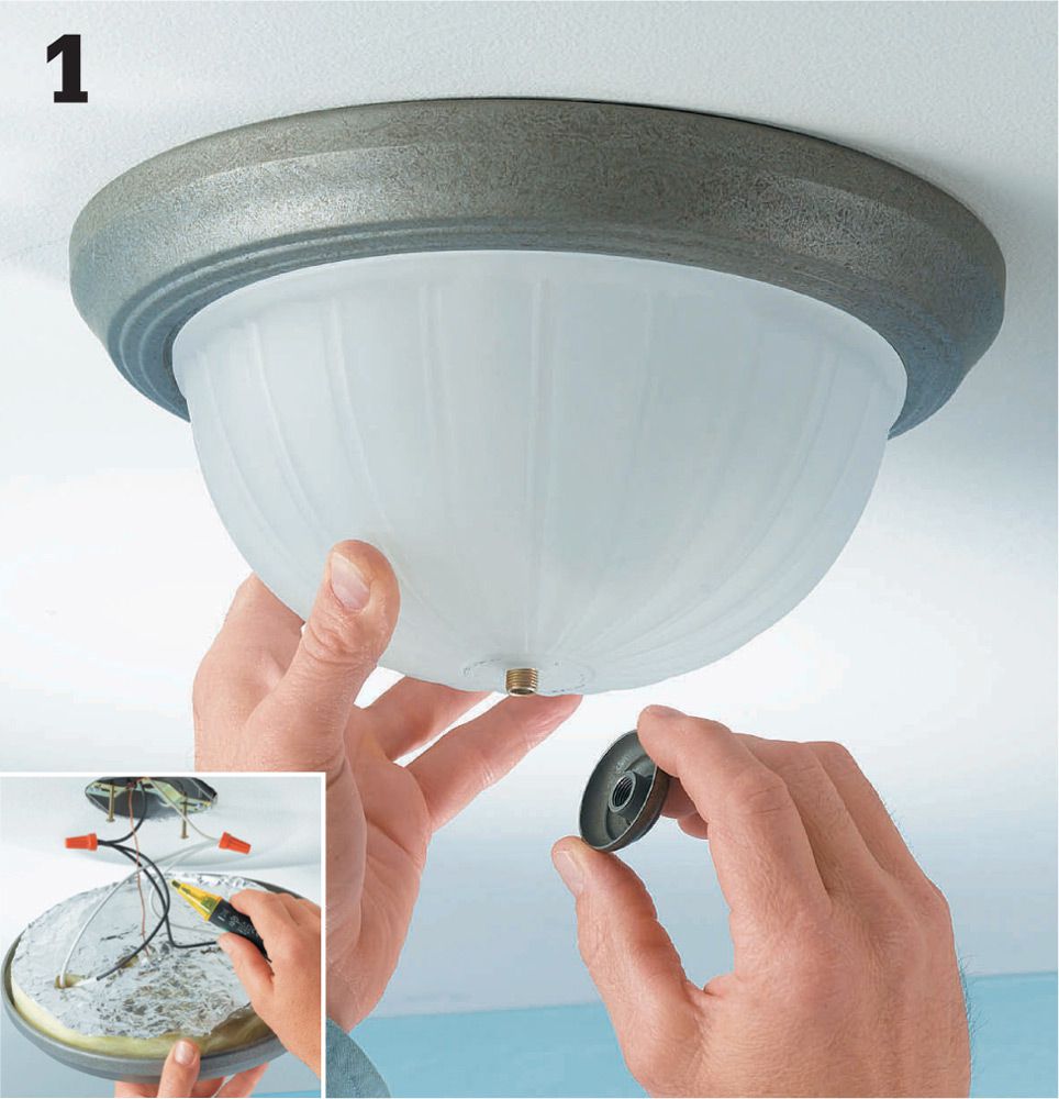
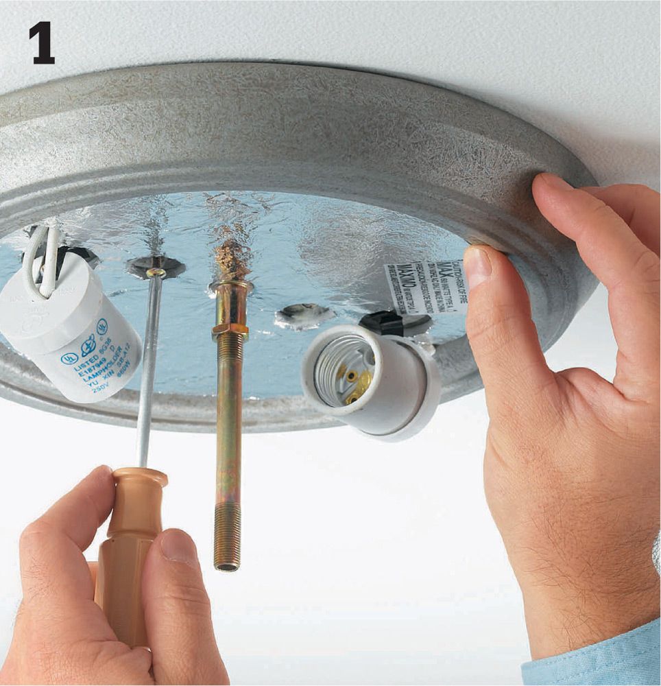
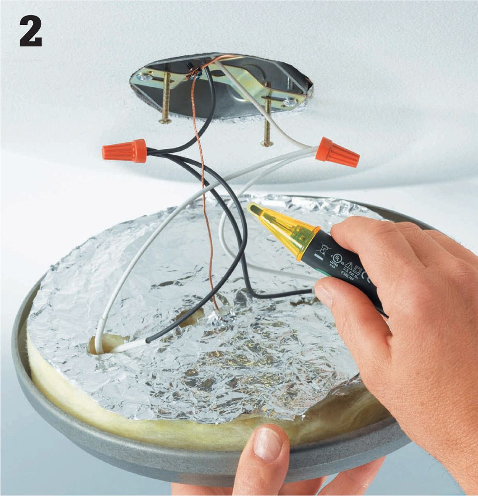
Shut off power to the ceiling light, and remove the shade or diffuser. Loosen the mounting screws and carefully lower the fixture, supporting it as you work (do not let light fixtures hang by their electrical wires alone). Test with a voltage sensor to make sure no power is reaching the connections.
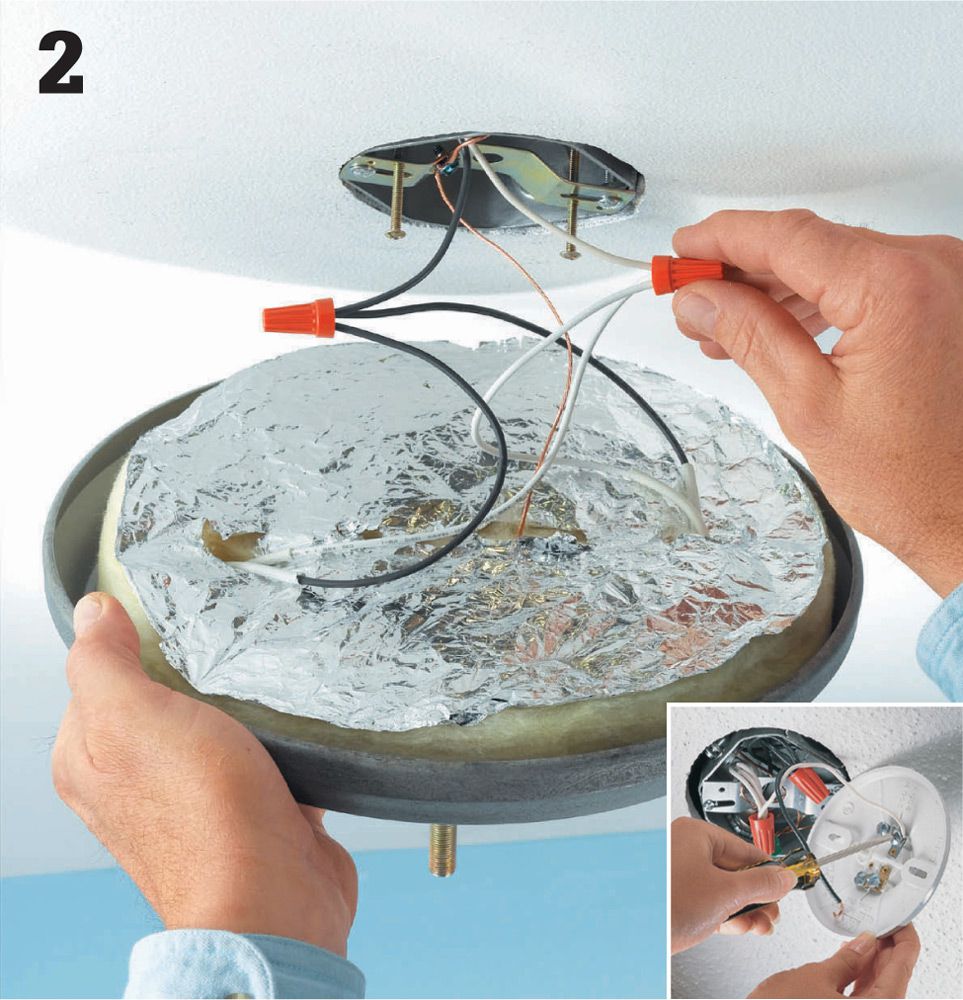
Remove the twist connectors from the fixture wires or unscrew the screw terminals and remove the white neutral wire and the black lead wire (inset).
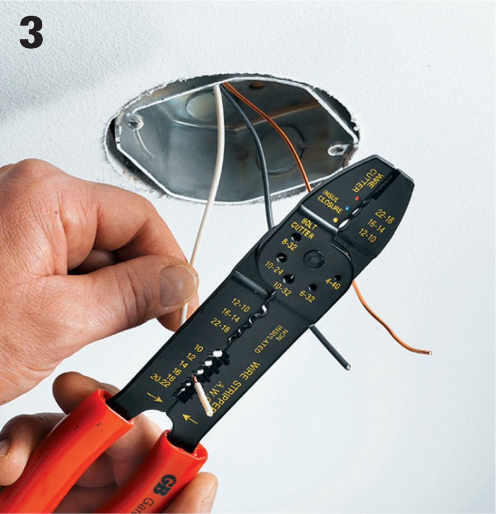
Before you install the new fixture, check the ends of the wires coming from the ceiling electrical box. They should be clean and free of nicks or scorch marks. If they’re dirty or worn, clip off the stripped portion with your combination tool. Then strip away about 3/4" of insulation from the end of each wire.
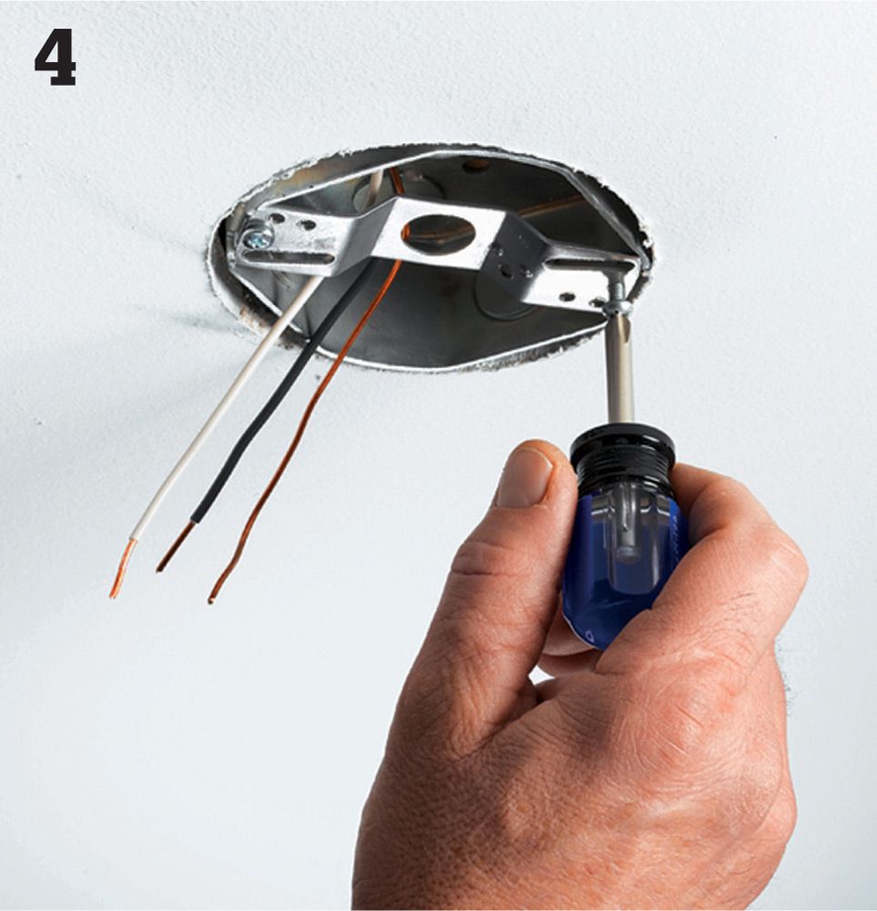
Attach a mounting strap to the ceiling fixture box if there is not one already present. Your new light may come equipped with a strap; otherwise you can find one for purchase at any hardware store.
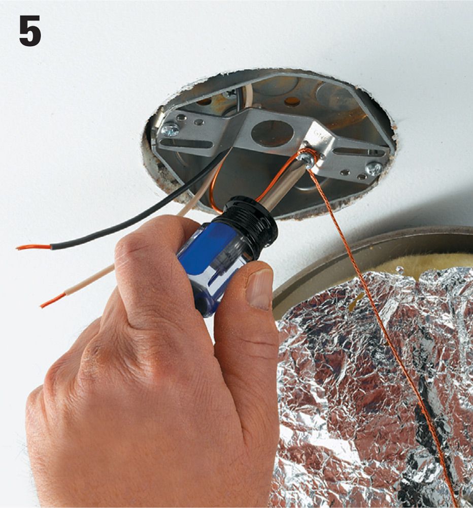
Lift the new fixture up to the ceiling (you may want a helper for this), and attach the bare copper ground wire from the power supply cable to the grounding screw or clip on the mounting strap. Also attach the ground wire from the fixture to the screw or clip.
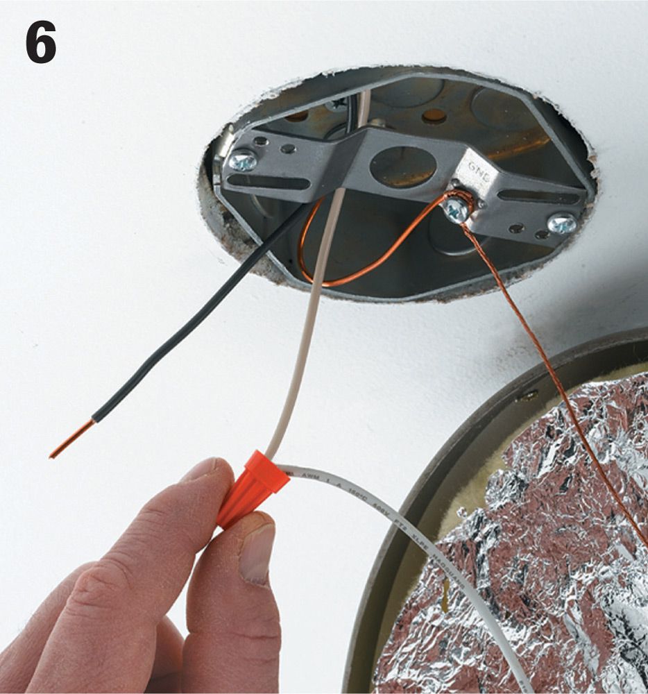
With the fixture supported by a ladder or a helper, join the white wire lead and the white fixture wire with a wire connector (often supplied with the fixture).
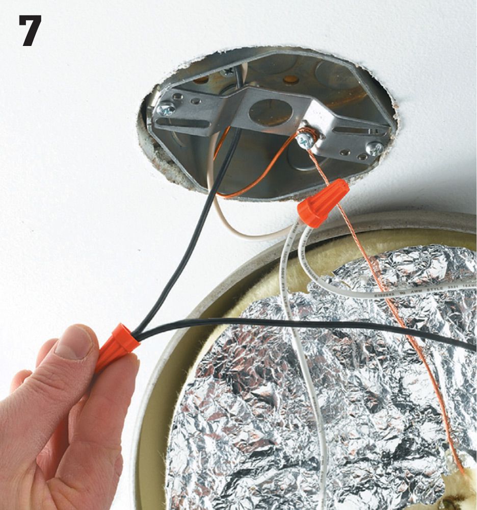
Connect the black power supply wire to the black fixture wire with a wire connector.
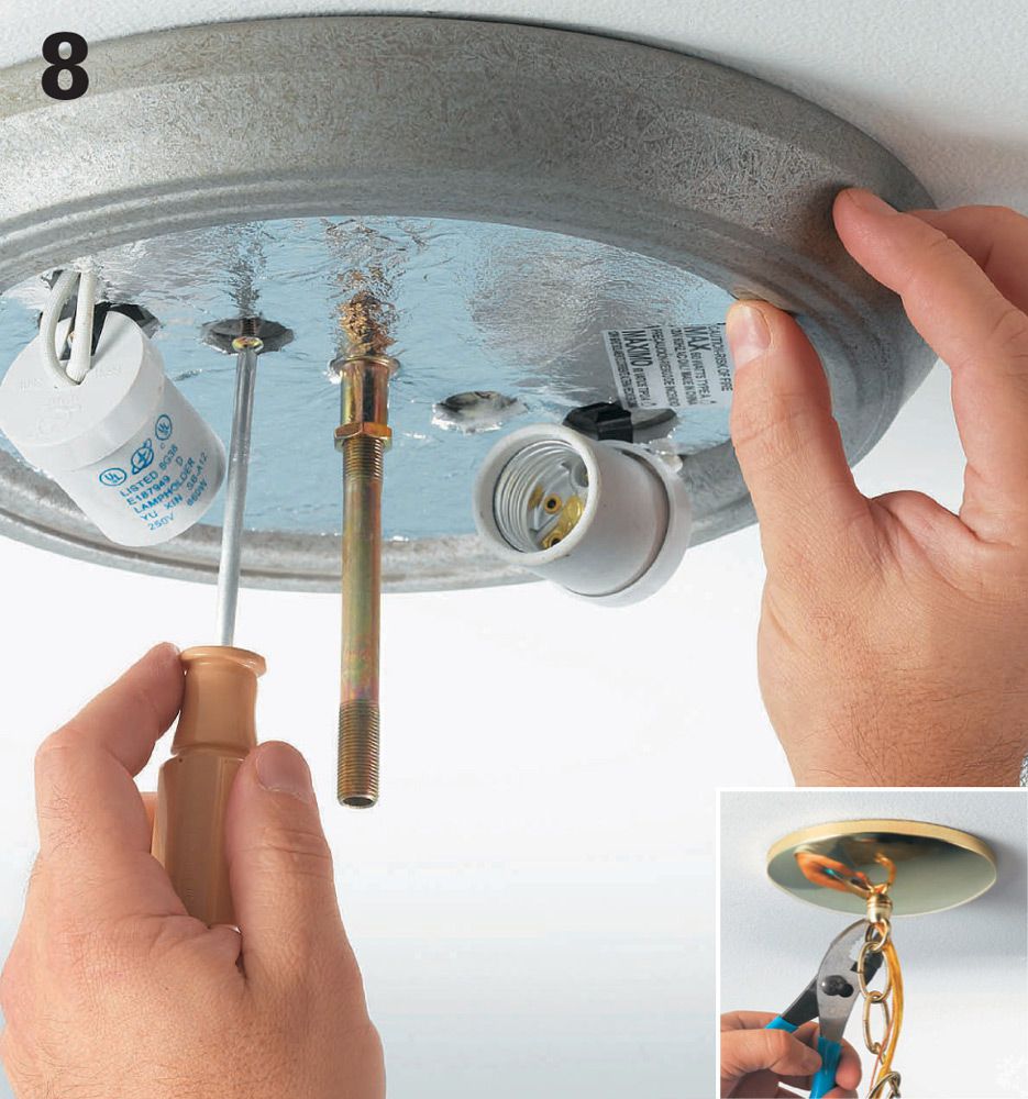
Position the new fixture mounting plate over the box so the mounting screw holes align. Drive the screws until the fixture is secure against the ceiling. Note: Some fixtures are supported by a threaded rod or nipple in the center that screws into a female threaded opening in the mounting strap (inset).
![]() Recessed Ceiling Lights
Recessed Ceiling Lights
Recessed lights are versatile fixtures suited for a variety of situations. Fixtures rated for outdoor use can also be installed in roof soffits and overhangs for accent and security lighting. Recessed fixtures can also be installed over showers or tubs. Be sure to use fixture cans and trims rated for bathroom use.
There are recessed lighting cans in all shapes and sizes for almost every type of ceiling or cabinet. Cans are sold for unfinished ceilings (new construction) or for finished ceilings (retrofit installation). Cans are also rated as insulation compatible or for uninsulated ceilings. Be sure to use the correct one for your ceiling to prevent creating a fire hazard. The 2012 International Residential Code requires that recessed lights installed in unconditioned spaces (such as attics) be insulation contact (IC) rated, air tight, and sealed to the drywall.


Choose the proper type of recessed light fixture for your project. There are two types of fixtures: those rated for installation within insulation (above), and those which must be kept at least 3" from insulation (below). Self-contained thermal switches shut off power if the unit gets too hot for its rating. A recessed light fixture must be installed at least 1/2" from combustible materials.
Tools & Materials ![]()
Recessed-lighting can for new construction or remodeling and trim
Circuit tester
Cable ripper
Combination tool
Pliers
Fish tape
Hack saw
Drywall saw
NM cable
Work gloves
Eye protection
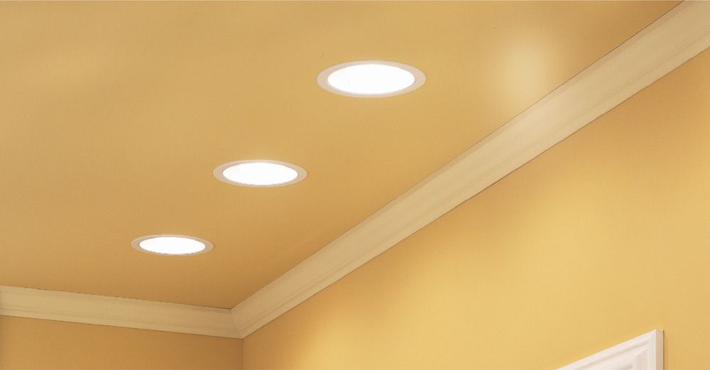
Recessed ceiling lights often are installed in series to provide exacting control over the amount and direction of light. Spacing the canisters in every other ceiling joist bay is a common practice.
![]() Recessed Materials
Recessed Materials
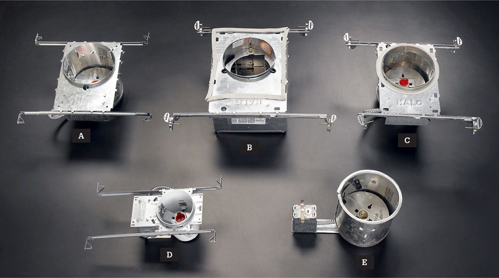
Recessed ceiling light housings come in many sizes and styles for various purposes and budgets. Some are sold with trim kits (below) included. Some common types are: new construction recessed housing (sold in economical multipacks) (A); airtight recessed housings (for heated rooms below unheated ceilings) (B); shallow recessed housings (for rooms with 2" × 6" ceiling joists) (C); small aperture recessed housing (D); recessed slope ceiling housing (for vaulted ceilings) (E).
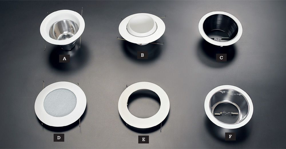
Trim kits for recessed ceiling lights may be sold separately. Common types include: open trim with reflective baffle (A); eyeball trim (B); baffle trim (black) (C); shower light trim (D); open trim (E); baffle trim (full reflective) (F).
![]() How to Install Recessed Ceiling Lights
How to Install Recessed Ceiling Lights
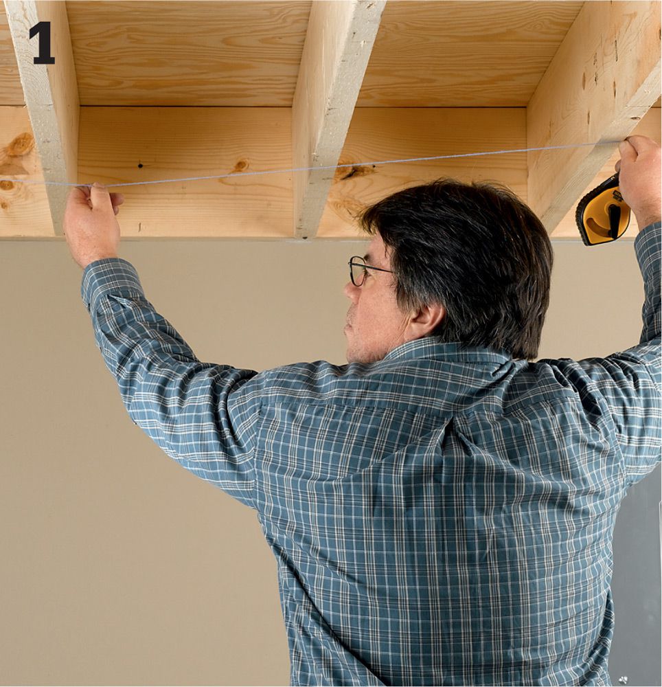
Mark the location for the light canister. If you are installing multiple lights, measure out from the wall at the start and end of the run, and connect them with a chalkline snapped parallel to the wall. If the ceiling is finished with a surface (wallboard), see next page.
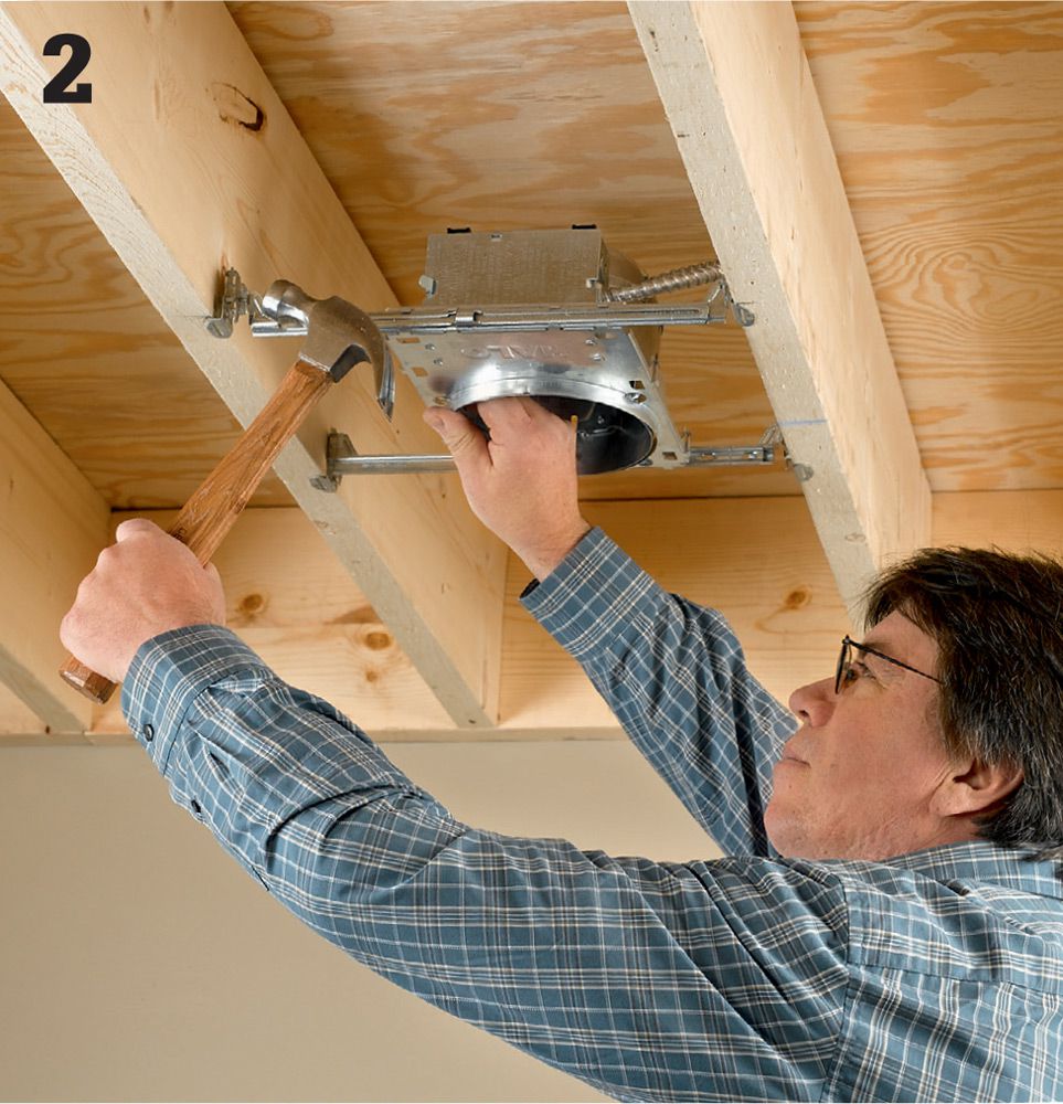
Install the housing for the recessed fixture. Housings for new construction (or remodeling installations where the installation area is fully accessible from either above or below) have integral hanger bars that you attach to each joist in the joist bay.
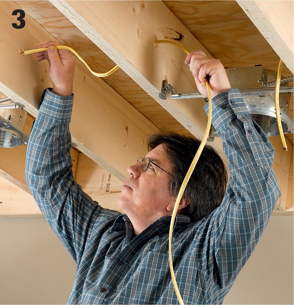
Run electric cable from the switch to each canister location. Multiple lights are generally installed in series so there is no need to make pigtail connections in the individual boxes. Make sure to leave enough extra cable at each location to feed the wire into the housing and make the connection.
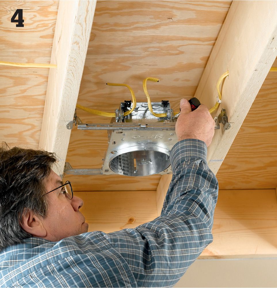
Run the feeder cables into the electrical boxes attached to the canister housings. You’ll need to remove knockouts first and make sure to secure the cable with a wire staple within 8" of the entry point to the box.
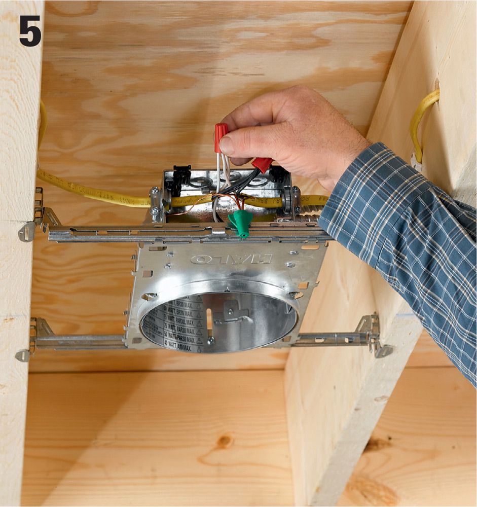
Connect the feeder wires to the fixture wires inside the junction box. Twist the hot lead together with the black fixture wire, as well as the black lead to other fixtures further downline. Also connect the neutral white wires. Join the ground wires and pigtail them to the grounding screw or clip in the box. Finish the ceiling, as desired.
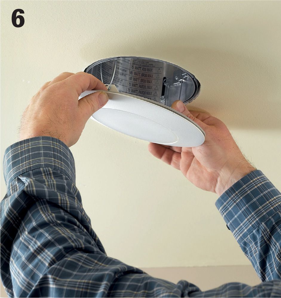
Attach your trim kit of choice. Normally these are hung with torsion spring clips from notches or hooks inside the canister. This should be done after the ceiling is installed and finished for new construction projects. With certain types of trim kits, such as eyeball trim, you’ll need to install the light bulb before the trim kit.
![]() How to Connect a Recessed Fixture Can in a Finished Ceiling
How to Connect a Recessed Fixture Can in a Finished Ceiling

Make the hole for the can. Most fixtures will include a template for sizing the hole. Fish 14/2 cable from the switch location to the hole. Pull about 16" of cable out of the hole for making the connection.
Remove a knockout from the electrical box attached to the can. Thread the cable into the box; secure it with a cable clamp. Remove sheathing insulation. Connect the black fixture wire to the black circuit wire, the white fixture wire to the white circuit wire, and then connect the ground wire to the grounding screw or grounding wire attached to the box.

Retrofit cans secure themselves in the hole with spring-loaded clips. Install the can in the ceiling by depressing the mounting clips so the can will fit into the hole. Insert the can so that its edge is tight to the ceiling. Push the mounting clips back out so they grip the drywall and hold the fixture in place. Install the trim piece.
![]() Track Lights
Track Lights
Track lighting offers a beautiful and functional way to increase the amount of light in a room or simply to update its look. A variety of fixture and lamp options let you control the shape, color, and intensity of the light. Installing track lighting in place of an existing ceiling-mounted light fixture involves basic wiring and hand-tool skills, but the connections are even easier to make than with traditional light fixtures. Once installed, the system is very easy to upgrade or expand in the future.
Tools & Materials ![]()
Drill/driver and bits
Wire stripper
Screwdriver
Voltage sensor
Toggle bolts
Track light heads
Prewired track and fittings
Wire connector
Ceiling box
Eye protection
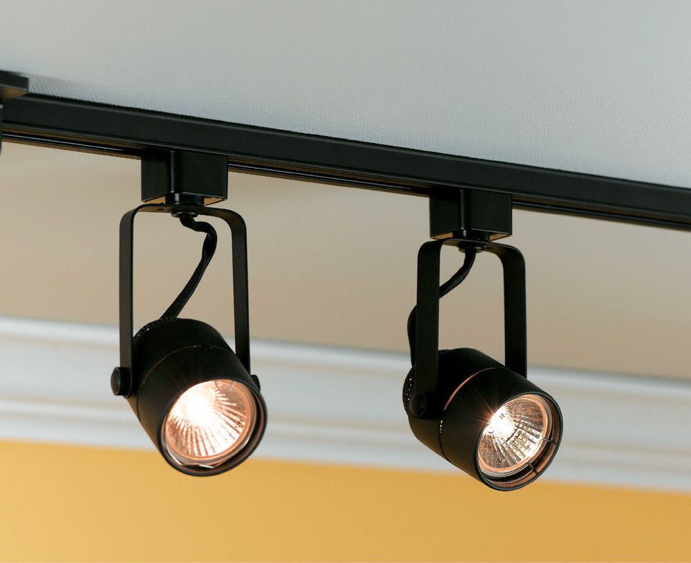
If you currently have a ceiling-mounted light fixture that is not meeting your lighting needs, it’s simple to replace it with a track-lighting fixture. With track lighting you can easily change the type and number of lights, their position on the track, and the direction they aim. These fixtures come in many different styles, including short 3-ft. track systems with just one or two lights up to 12-ft. systems with five or more lights.
![]() How to Install Track Lighting
How to Install Track Lighting
Disconnect the old ceiling light fixture (for remodeling projects) after shutting off power to the circuit at the main service panel. The globe or diffuser and the lamps should be removed before the fixture mounting mechanism is detached.
Test the fixture wires with a voltage sensor to make sure the circuit is dead. Support the fixture from below while you work—never allow a light fixture to hang by its electrical wires alone. Remove the wire connectors and pull the wires apart. Remove the old light fixture.
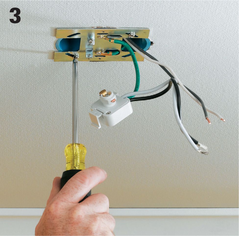
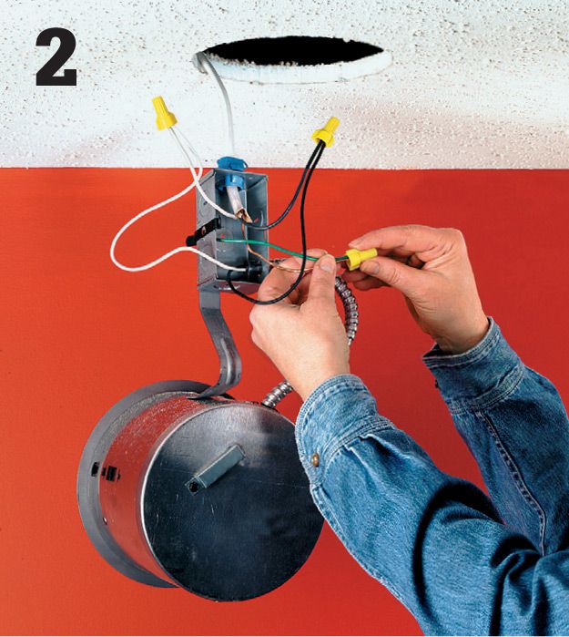
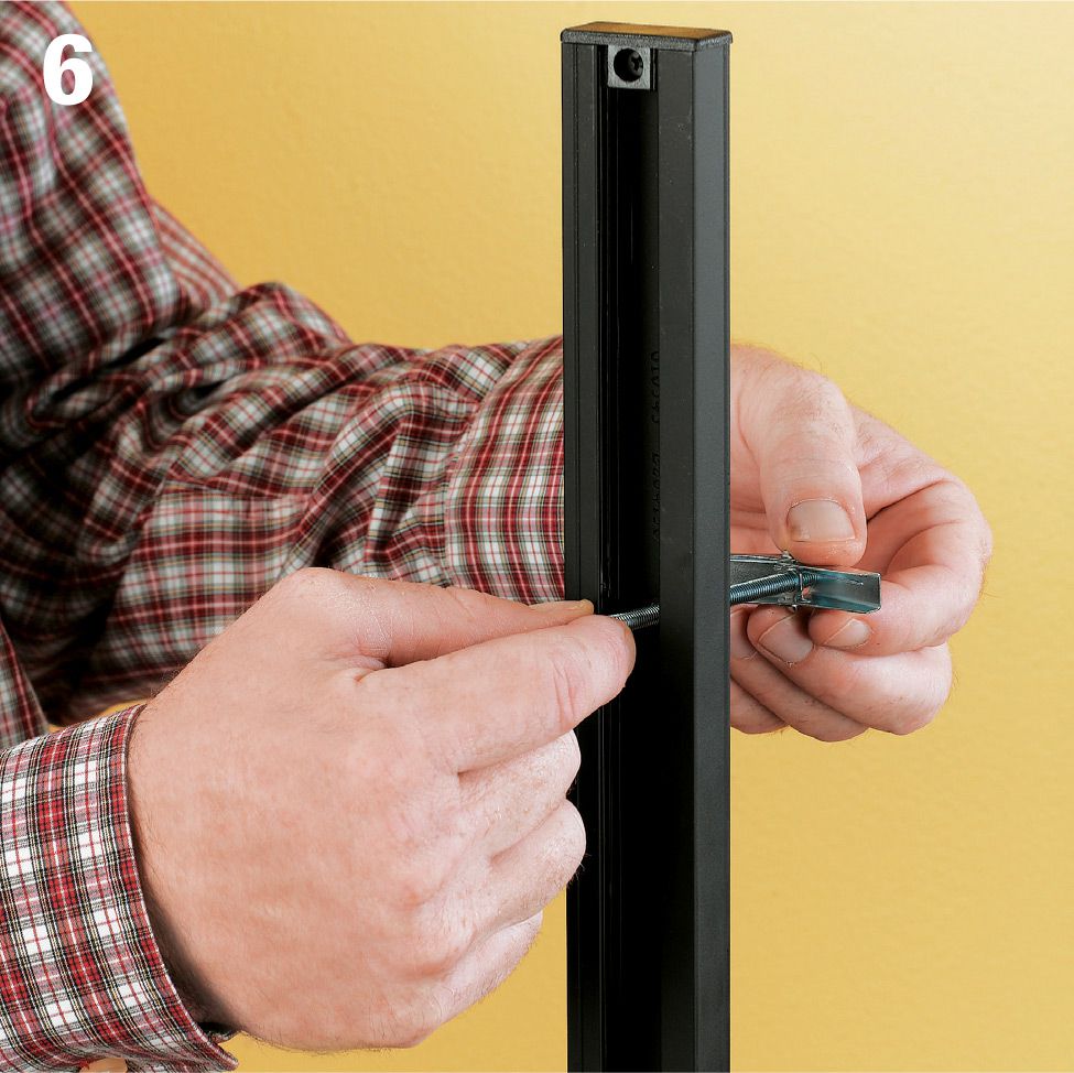
Attach the mounting strap for the new track light to the old ceiling box. If the mounting strap has a hole in the center, thread the circuit wires through the hole before screwing the strap to the box. The green or bare copper ground from the circuit should be attached to the grounding screw or clip on the strap or box.
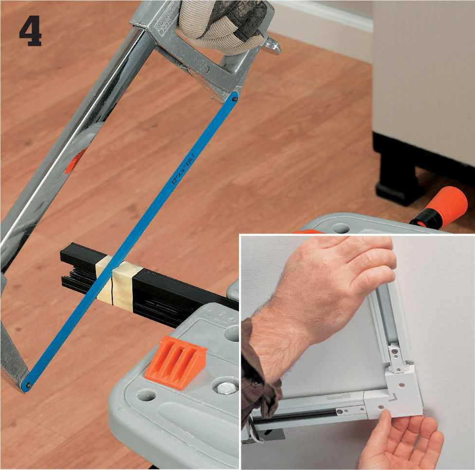
Cut the track section to length, if necessary, using a hack saw. Deburr the cut end with a metal file. If you are installing multiple sections of track, assemble the sections with the correct connector fittings (sold separately from your kit). You can also purchase T-fittings or L-fittings (inset photo) if you wish to install tracks in either of these configurations.
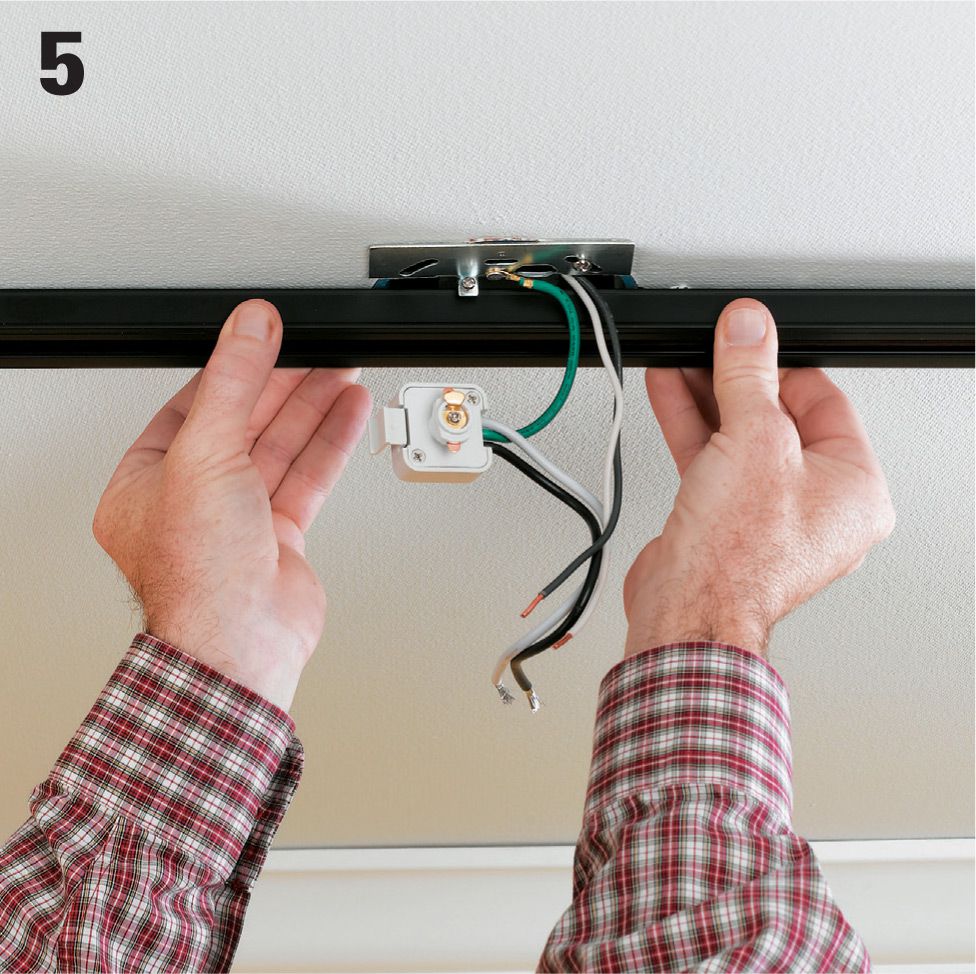
Position the track section in the mounting saddle on the mounting strap and hold it temporarily in place in the location where it will be installed. The track section will have predrilled mounting holes in the back. Draw a marking point on the ceiling at each of these locations. If your track does not have predrilled mounting holes, remove it and drill a 3/16" hole in the back every 16".
Insert the bolt from a toggle bolt or molly bolt into each predrilled screw location and twist the toggle or molly back onto the free end. These types of hardware have greater holding power than anchor sleeves. Drill a 5/8" dia. access hole in the ceiling at each of the mounting hole locations you marked on the ceiling in step 5.
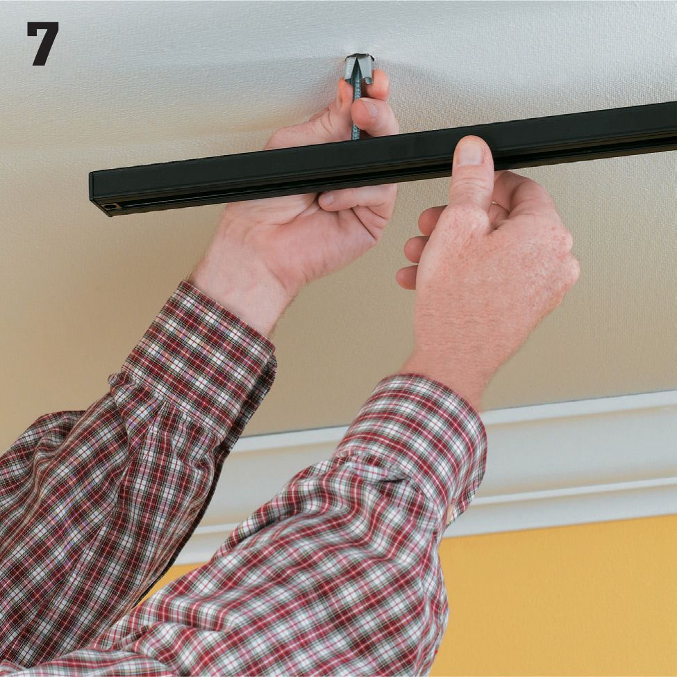
Insert the toggle or molly into the access hole far enough so it clears the top of the hole and the wings snap outward. Then tighten each bolt so the track is snug against the ceiling. If the mounting hole happens to fall over a ceiling joint, simply drive a wallboard screw at that hole location.
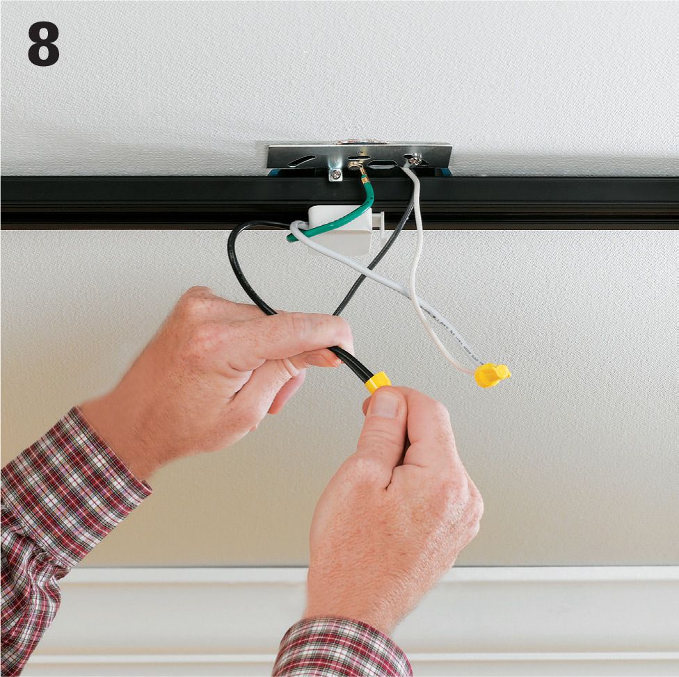
Hook up wires from the track’s power supply fitting to the circuit wires. Connect black to black and white to white. The grounding wire from the power supply fitting can either be pigtailed to the circuit ground wire and connected to the grounding screw or clip, or it can be twisted together with the circuit grounding wire at the grounding terminal. Snap the fitting into the track if you have not already done so.
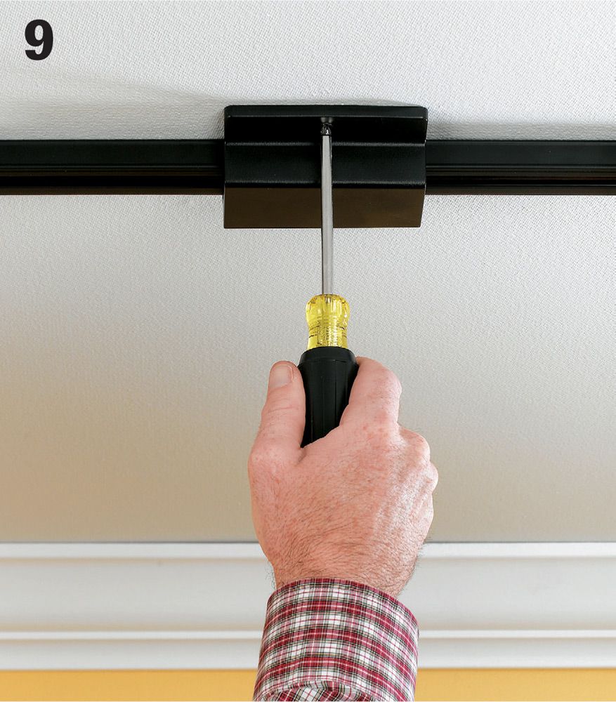
Attach the protective cover that came with your kit to conceal the ceiling box and the electrical connections. Some covers simply snap in place, others require a mounting screw.
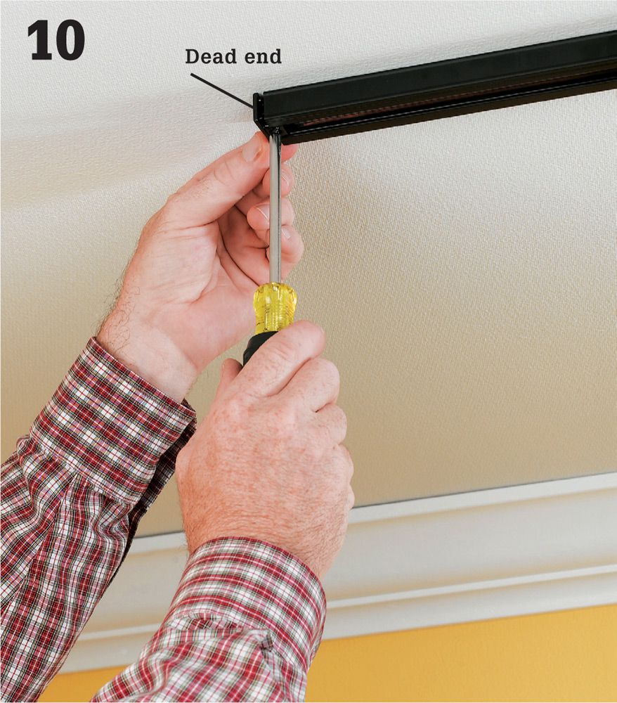
Cap the open ends of the track with a dead end cap fitting. These also may require a mounting screw. Leaving track ends open is a safety violation.
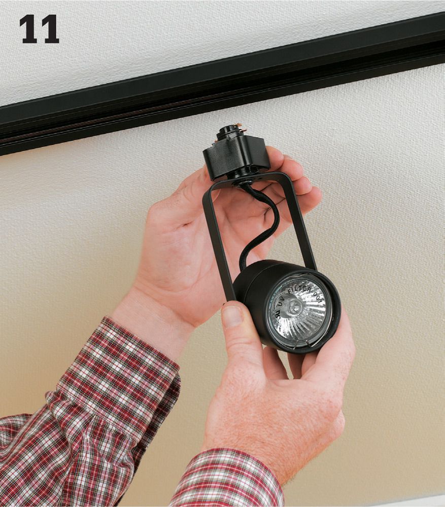
Insert the light heads into the track by slipping the stem into the track slot and then twisting it so the electrical contact points on the head press against the electrified inner rails of the track slot. Tug lightly on the head to make sure it is secure before releasing it.
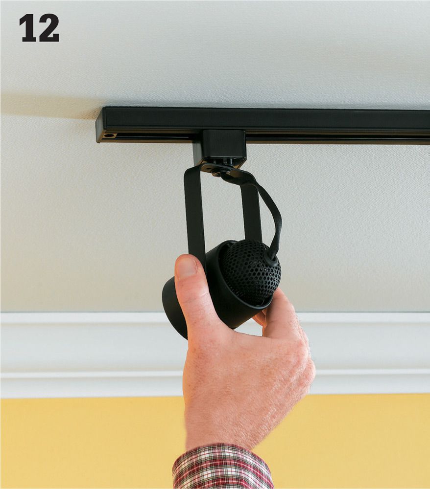
Arrange the track light heads so their light falls in the manner you choose, and then depress the locking tab on each fixture to secure it in position. Restore power, and test the lights.
![]() Undercabinet Lights
Undercabinet Lights
Hardwired undercabinet lights illuminate the kitchen countertop and sink areas that fall in the shadow of ceiling lights. Most of these light fixtures, which are often called strip lights, utilize fluorescent, halogen, or xenon bulbs that emit very low levels of heat and are therefore very efficient.
If you are doing a kitchen remodel with all-new cabinets, run the new light circuit wiring before the cabinets are installed. For a retrofit, you’ll need to find an available power source to tie into. Options for this do not include the dedicated 20-amp small-appliance receptacle circuits that are required in kitchens. The best bet is to run new circuit wire from a close-by ceiling light switch box, but this will mean cutting into the walls to run cable. Another option is to locate a receptacle that’s on the opposite side of a shared wall, preferably next to a location where a base cabinet is installed in the kitchen. This room should not be a breakfast room, dining, room, pantry, or similar area, because these rooms are also served by the small appliance receptacle circuits. By cutting an access hole in the cabinet back you can tie into the receptacle box and run cable through the wall behind the cabinets, up to the upper cabinet location, and out the wall to supply the fixture that’s mounted to the underside of the upper cabinet.
You can purchase undercabinet lights that are controlled by a wall switch, but most products have an integral on/off button so you can control lights individually.
Tools & Materials ![]()
Circuit tester
Utility knife
Wallboard saw
Hammer
Screwdriver
Drill and hole saw
Jigsaw
Wire stripper
Undercabinet lighting kit
14/2 NM cable
Wire connectors
Switch box
Switch
Eye protection
Hardboard panel adhesive
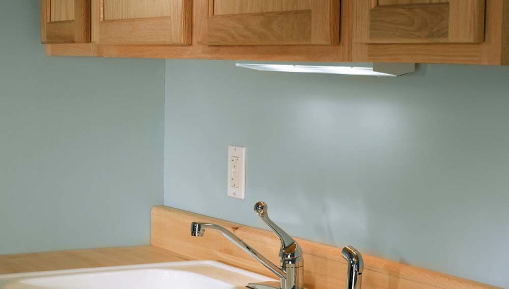
Undercabinet lights provide directed task lighting that bring sinks and countertop work surfaces out from the shadows. Hardwired lights may be controlled either by a wall switch or an onboard on/off switch located on the fixture. Note: Do not supply power for lights from the small-appliance circuit.
![]() How to Install a Hardwired Undercabinet Light
How to Install a Hardwired Undercabinet Light
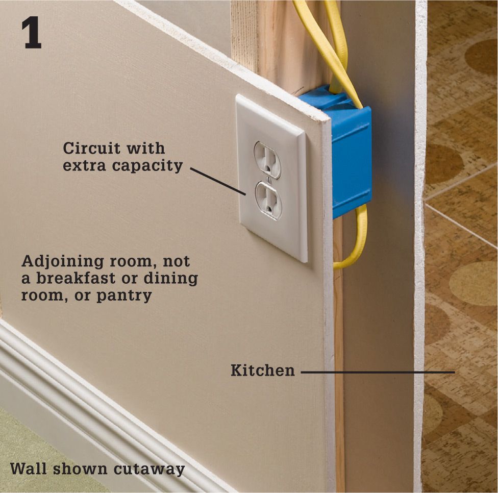
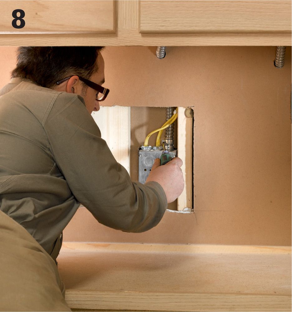
Look in the adjoining room for a usable power source in the form of a receptacle that has a box located in the wall behind your base cabinets. Unlike the small-appliance circuit with outlets in your backsplash area, these typically are not dedicated circuits (which can’t be expanded). Make sure that the receptacle’s circuit has enough capacity to support another load. Shut the power to the receptacle off at the main service panel and test for power.
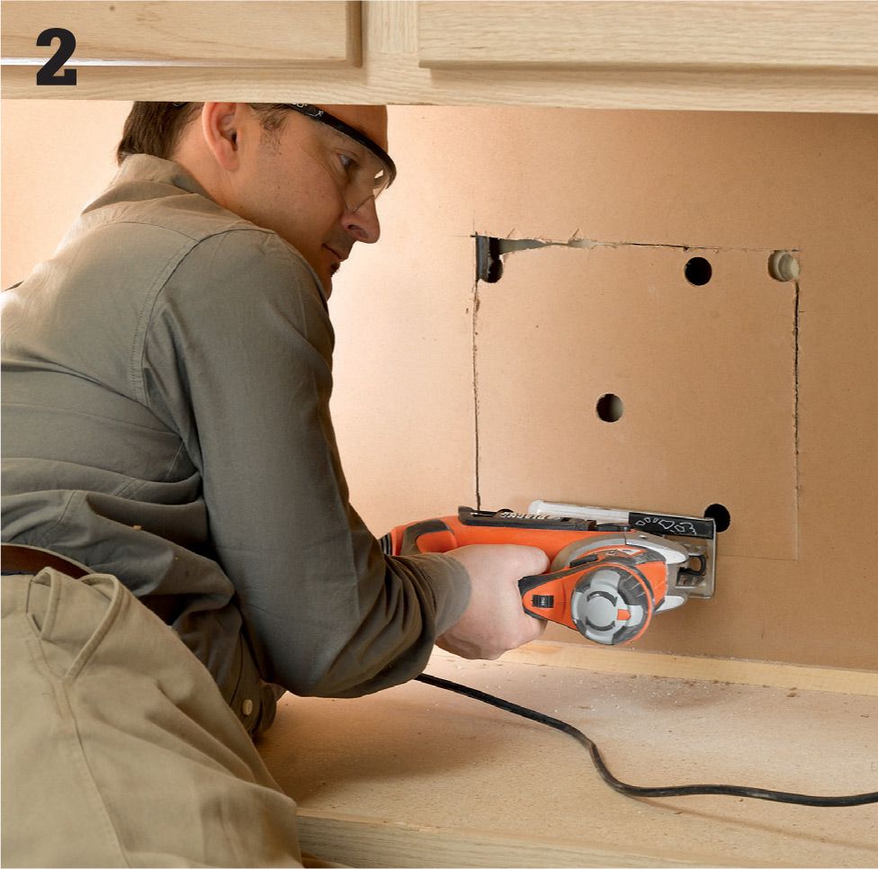
Cut a hole in the base cabinet back panel to get access to the wall behind it in roughly the area where you know the next-door receptacle to be. Use a keyhole saw or drywall saw and make very shallow cuts until you have positively identified the locations of the electrical box and cables. Then finish the cuts with a jigsaw.
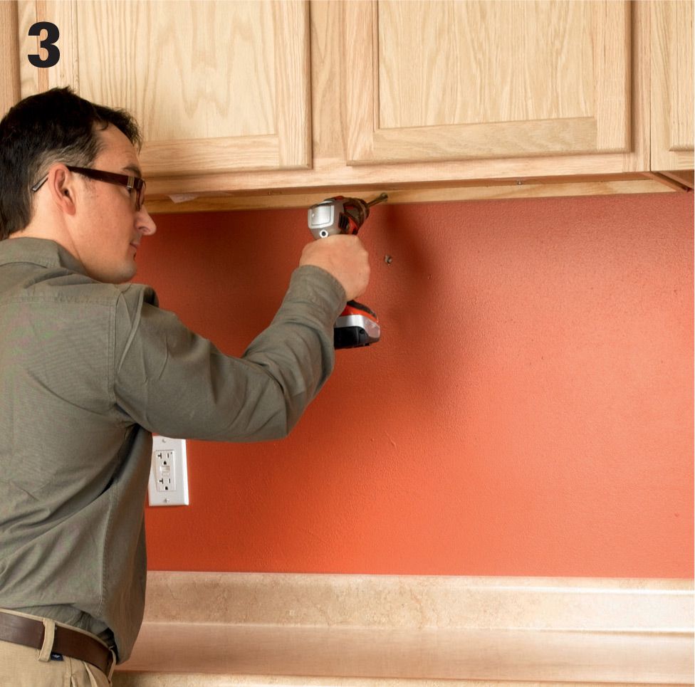
Drill an access hole into the kitchen wall for the cable that will feed the undercabinet light. A 1/2" dia. hole should be about the right size if you are using 12-ga. or 14-ga. sheathed NM cable.
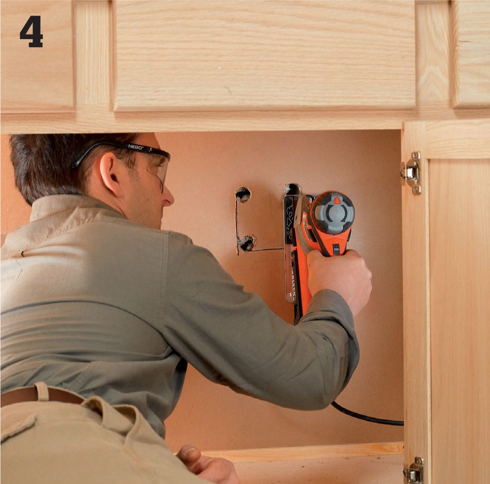
Cut a small access hole (4" × 4" or so) in the back panel of the base cabinet directly below the undercabinet light location.
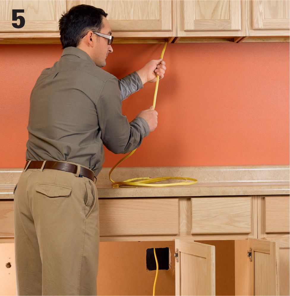
Feed cable into the access hole at the light location until the end reaches the access hole below. Don’t cut the cable yet. Reach into the access hole and feel around for the free cable end, and then pull it out through the access hole once you’ve found it. Cut the cable, making sure to leave plenty of extra on both ends.
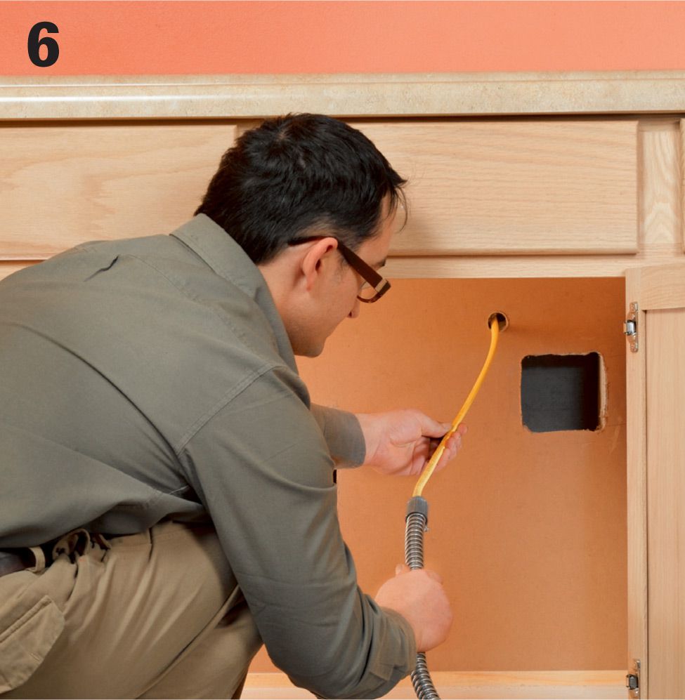
String the cable into a piece of flexible conduit that’s long enough to reach between the two access holes in the base cabinets. Attach a connector to each end of the conduit to protect the cable sheathing from the sharp edges of the cut metal. Tip: To make patching the cabinet back easier, drill a new access hole for the cable near the square access hole.
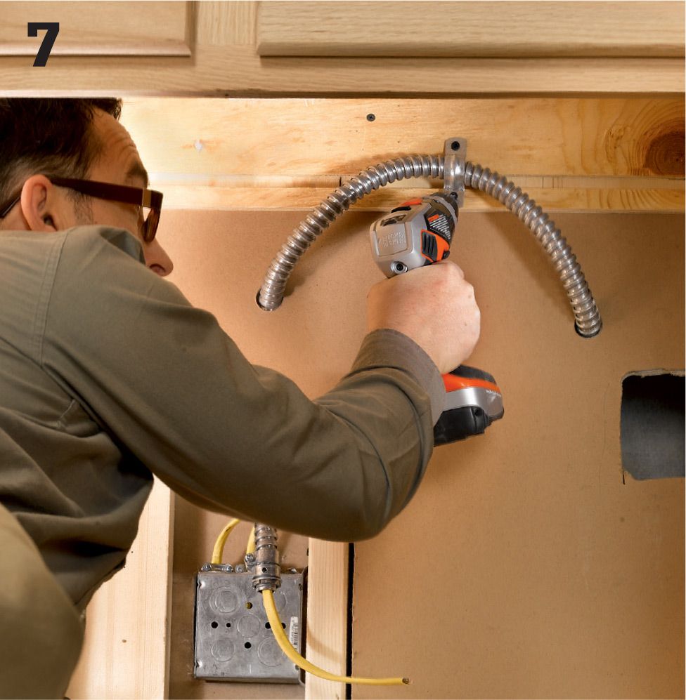
Hang the conduit with hanger straps attached to the base cabinet frame or back panel, drilling holes in the side walls of the cabinet where necessary to thread the conduit through. On back panels, use small screws to hang the straps instead of brads or nails. Support the conduit near both the entrance and the exit holes (the conduit should extend past the back panels by a couple of inches).
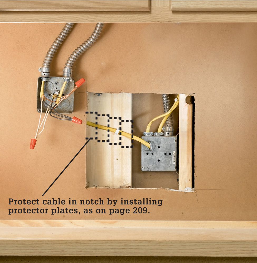
Variation: If you are installing more than one undercabinet light, run cable down from each installation point as you did for the first light. Mount an electrical junction box to the cabinet back near the receptacle providing the power. Run the power cables from each light through flexible conduit and make connections inside the junction box. Be sure to attach the junction box cover once the connections are made.
Remove the receptacle from the box you are tying into and insert the new circuit cable into one of the knockouts using a cable clamp. Check a wire capacity chart (see page 26) to make sure the box is big enough for the new conductors. Replace it with a larger box if necessary. Reinstall the receptacle once the connections are made.
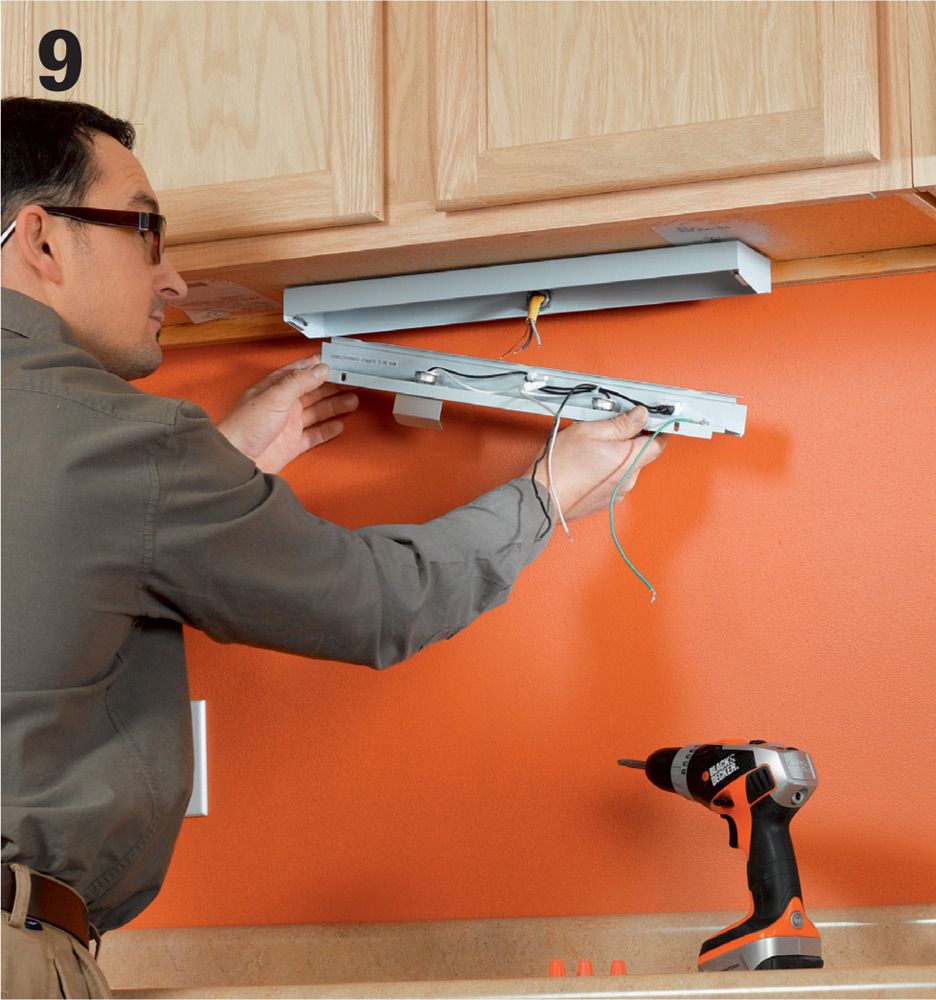
Install the undercabinet light. Some models have a removable diffuser that allows access to the fixture wires, and these should be screwed to the upper cabinet prior to making your wiring hookups. Other models need to be connected to the circuit wires before installation. Check your manufacturer’s installations.
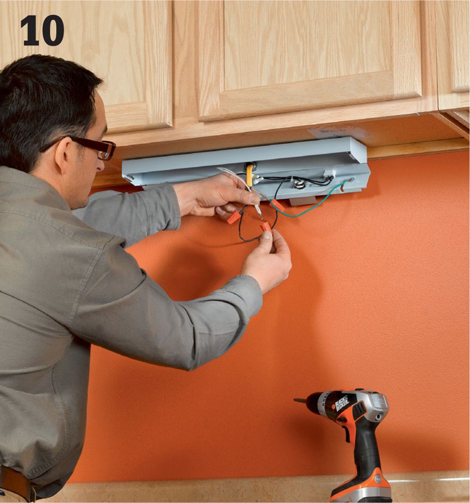
Connect wires inside the light fixture according to the light manufacturer’s directions. Make sure the incoming cable is stapled just before it enters the light box and that a cable clamp is used at the knockout in the box to protect the cable. Restore power, and test the light.
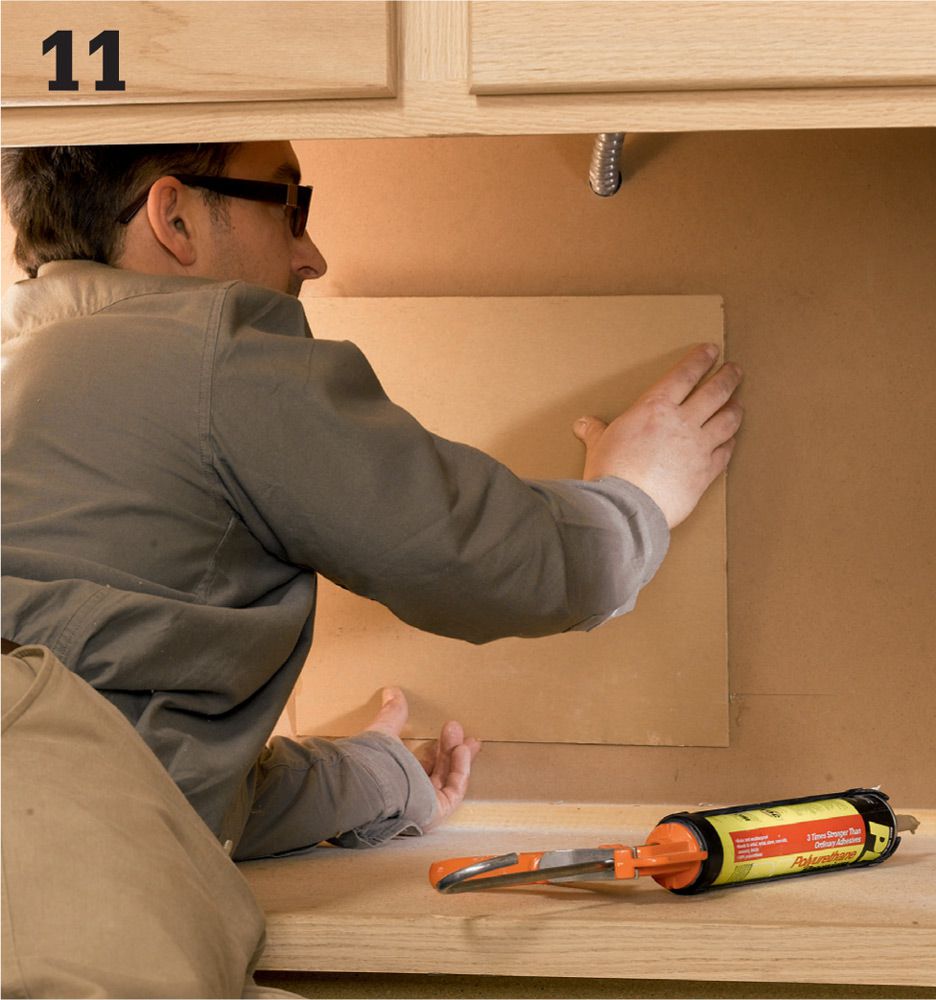
Cut patches of hardboard and fit them over the access holes, overlapping the edges of the cutouts. Adhere them to the cabinet backs with panel adhesive.
![]() Vanity Lights
Vanity Lights
Many bathrooms have a single fixture positioned above the vanity, but a light source in this position casts shadows on the face and makes grooming more difficult. Light fixtures on either side of the mirror is a better arrangement.
For a remodel, mark the mirror location, run cable, and position boxes before drywall installation. You can also retrofit by installing new boxes and drawing power from the existing fixture.
The light sources should be at eye level; 66" is typical. The size of your mirror and its location on the wall may affect how far apart you can place the sconces, but 36" to 40" apart is a good guideline.
Tools & Materials ![]()
Drywall saw
Drill
Combination tool
Circuit tester
Screwdrivers
Hammer
Electrical boxes and braces
Vanity light fixtures
NM cable
Wire connectors
Eye protection
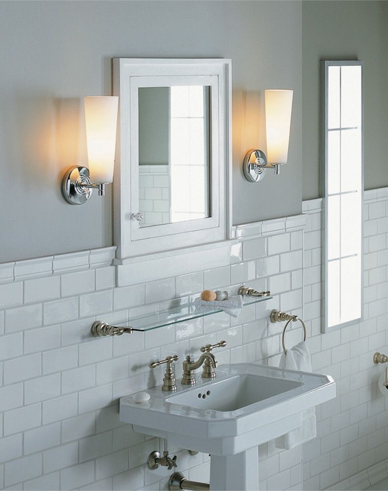
Vanity lights on the sides of the mirror provide good lighting.
![]() How to Replace Vanity Lights in a Finished Bathroom
How to Replace Vanity Lights in a Finished Bathroom
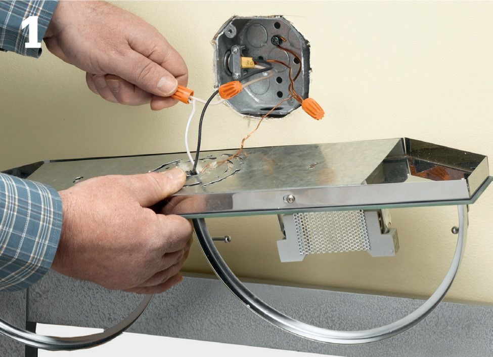
Turn off the power at the service panel. Remove the old fixture from the wall, and test to make sure that the power is off. Then remove a strip of drywall from around the old fixture to the first studs beyond the approximate location of the new fixtures. Make the opening large enough that you have room to route cable from the existing fixture to the boxes.
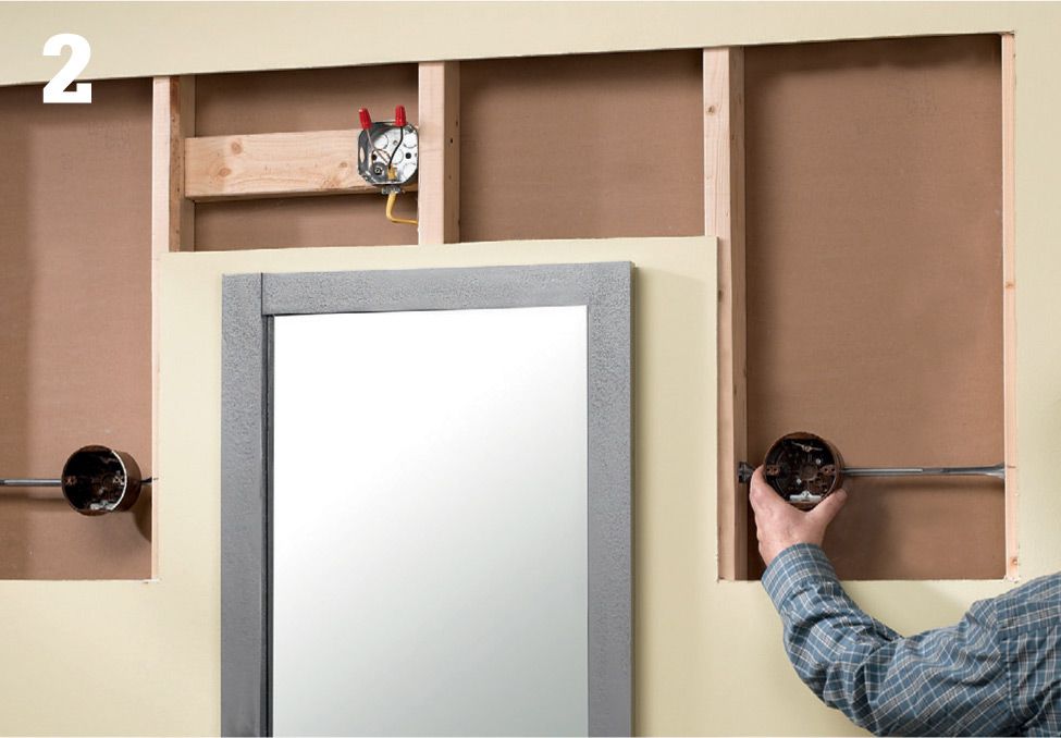
Mark the location for the fixtures, and install new boxes. Install the boxes about 66" above the floor and 18" to 20" from the centerline of the mirror (the mounting base of some fixtures is above or below the bulb, so adjust the height of the bracing accordingly). If the correct location is on or next to a stud, you can attach the box directly to the stud; otherwise you’ll need to install blocking or use boxes with adjustable braces (shown).
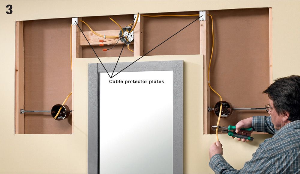
Open the side knockouts on the electrical box above the vanity. Then drill 5/8" holes in the centers of any studs between the old fixture and the new ones. Run two NM cables from the new boxes for the fixtures to the box above the vanity. Protect the cable with metal protector plates. Secure the cables with cable clamps, leaving 11" of extra cable for making the connection to the new fixtures. Remove sheathing, and strip insulation from the ends of the wires.
Connect the white wires from the new cables to the white wire from the old cable, and connect the black wires from the new cables to the black wire from the old cable. Connect the ground wires. Cover all open boxes, and then replace the drywall, leaving openings for the fixture and the old box. (Cover the old box with a solid junction box cover plate.)
Install the fixture mounting braces on the boxes. Attach the fixtures by connecting the black circuit wire to the black fixture wire and connecting the white circuit wire to the white fixture wire. Connect the ground wires. Position each fixture over each box, and attach with the mounting screws. Restore power, and test the circuit.
![]() Low-Voltage Cable Lights
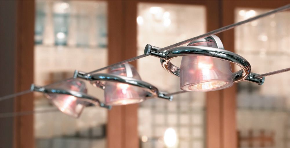
Low-Voltage Cable Lights
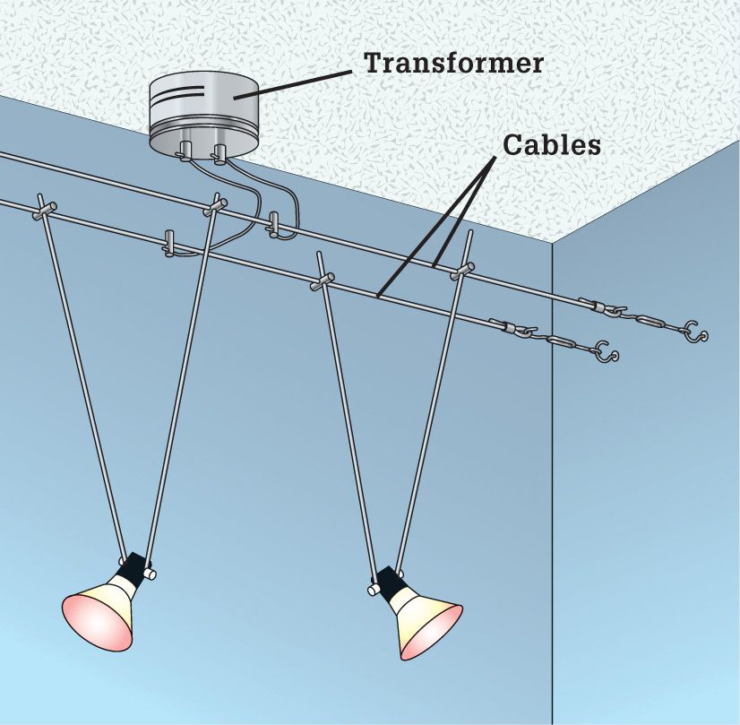
This unique fixture system is a mainstay of retail and commercial lighting and is now becoming common in homes. Low-voltage cable systems use two parallel cables to suspend and provide electricity to fixtures mounted anywhere on the cables. A 12-volt transformer feeds low-voltage power to the cables.
The system’s ease of installation, flexibility, and the wide variety of individual lights available make it perfect for all kinds of spaces. Low-voltage cable light systems are ideal for retrofits and for situations where surface-mounted track is undesirable or impossible to install.
Tools & Materials ![]()
Combination tool
Screwdriver
Drill
Fish tape
Low-voltage cable light kit
Switch
Electrical boxes
NM cable
Level
Eye protection
Low-voltage Cable Lighting Kit ![]()
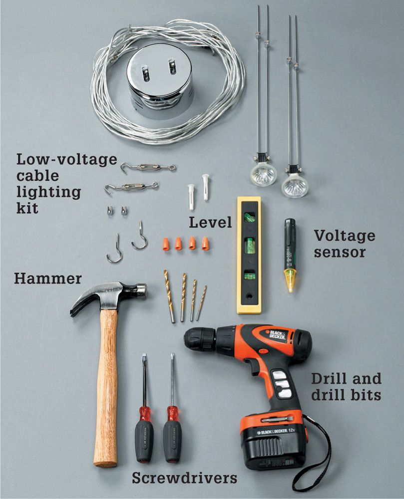
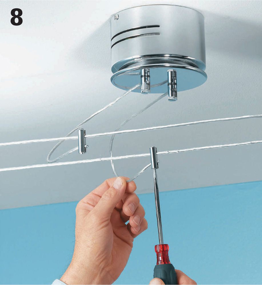
Low-voltage cable lights are low profile and easy to install, but they provide a surprising amount of light.
![]() How to Install Low-Voltage Landscape Lights
How to Install Low-Voltage Landscape Lights
Cable Light Kits ![]()
Low-voltage cable lights typically are sold in kits that contain the hanging lights, the low-voltage cable, and a decorative transformer that can be ceiling mounted or wall mounted.
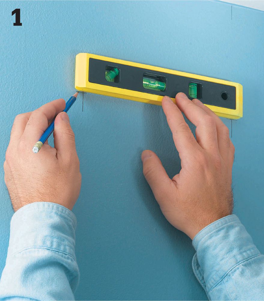
Lay out locations for the screw eyes that are used to suspend the cables, which should be in a parallel line. The path should lead the cables within a foot of the existing ceiling fixture box that you are using to provide power.
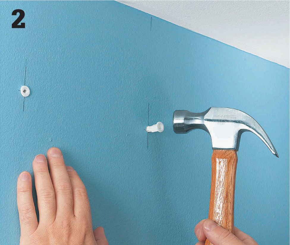
Install wall anchors at the appointed locations for the screw eyes that will suspend the cables. Plastic sleeve anchors are adequate in most cases. Drive the anchors into guide holes with a hammer.
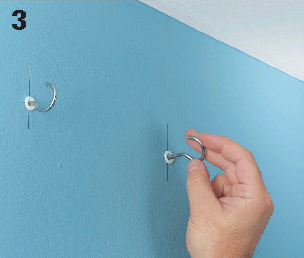
Twist the screw eyes into the wall anchor sleeves, taking care to make sure they are driven in equal amounts and are not overdriven. Install a set of screw eyes the same distance apart on each facing wall in the installation area. Cut two pieces of low-voltage cable to span between screw eyes on facing walls. Recommendations may vary — for the project shown here the cable is cut 12" shorter than the distance between the screw eyes.
Use the crimping hardware in your kit to form small loops at the ends of each cable. Slip the loops over the screw eyes on one end, and attach them to turnbuckles at the opposite ends. Slide the turnbuckles over the screw eyes and tighten them until the cables are taut.
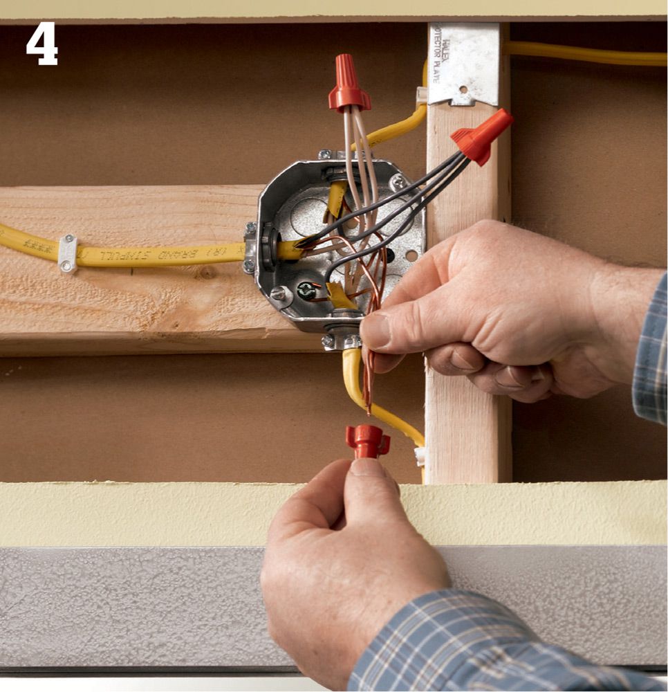
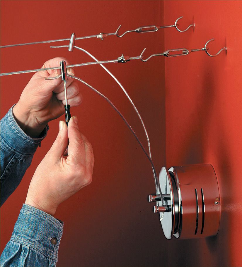
Attach the transformer crossbar to the electrical box containing the circuit leads. Shut off the power at the main service panel and test for power, and then remove the old fixture, if you have not already done so.
Make wiring connections for the transformer inside the electrical box. Make sure the transformer is supported while you join the wires. Be sure to attach the grounding wires to the grounding screw or clip in the box.
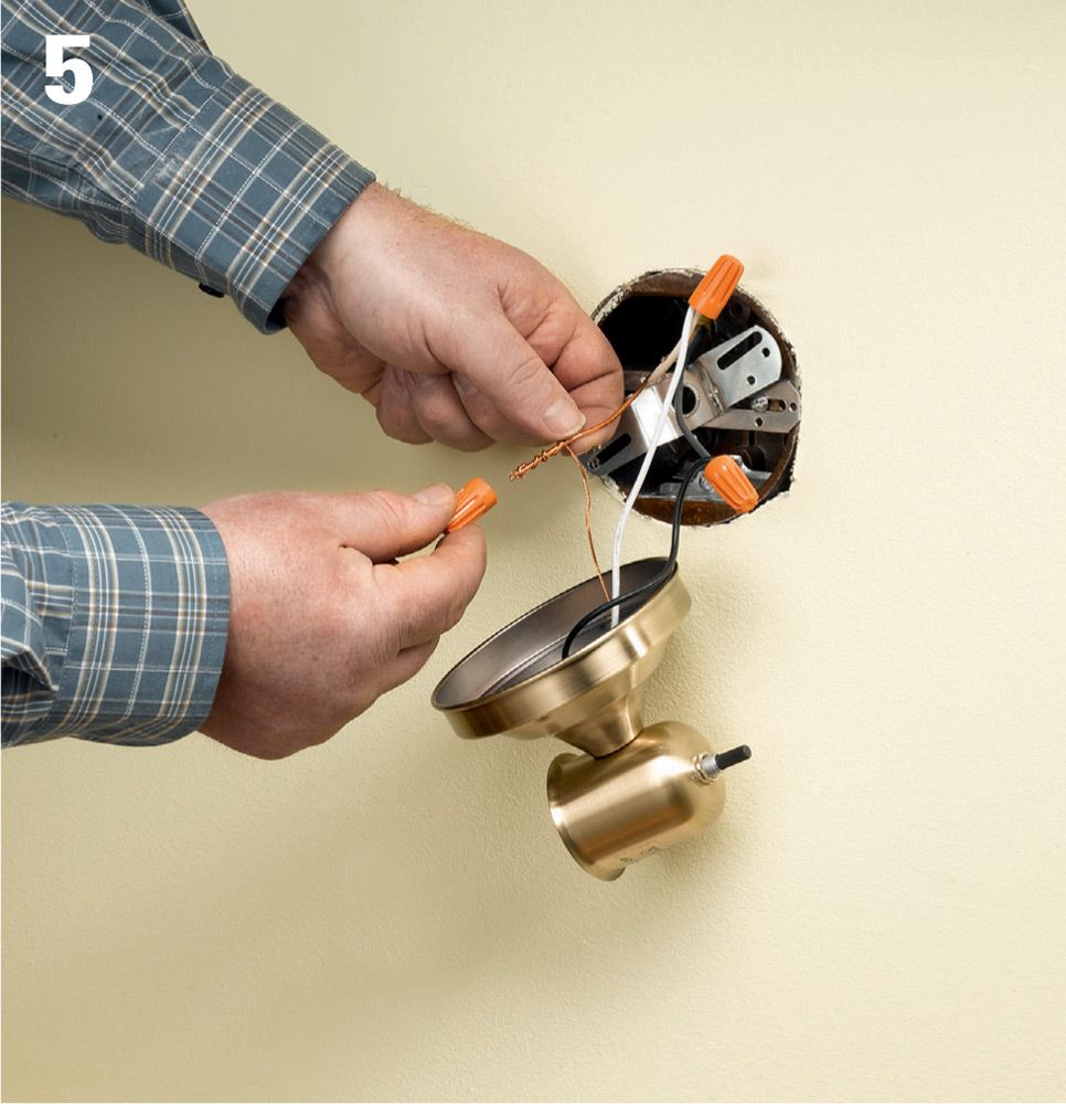
Mount the transformer onto the electrical box according to the manufacturer’s instructions. The model shown here has a separate chrome cover that is secured with a setscrew after the transformer is mounted to the crossbar.
Thread short lengths of cable into the openings on the screw terminals on the transformer. Tighten the screws until the pointed probe in each terminal pierces the cable sheathing and makes contact with the wire inside. Do the same with the other ends of the jumper cables using the provided connector hardware.

Hang the light fixture holders from the cables, tightening the screws in the hanger ends until their probes pierce the cable sheathing and make contact. It’s a good idea to hang all of the fixtures and arrange them to your liking before you begin tightening the screws and piercing the sheathing.
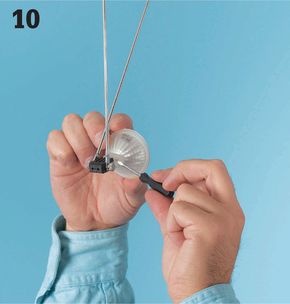
Insert the special low-voltage bulbs into the fixture holders and secure them as instructed (here, we are tightening a setscrew). Turn on the power and test the lights, adjusting the angles and directions of the bulbs.
Wall-Mount It ![]()
Install the transformer in a wall location if there is a more convenient power source or if you simply prefer the appearance of the wall location.
![]() Hard-Wired Smoke & CO Alarms
Hard-Wired Smoke & CO Alarms
Smoke and carbon monoxide (CO) alarms are an essential safety component of any living facility. All national fire protection codes require that new homes have a hard-wired smoke alarm in every sleeping room and on every level of a residence, including basements and habitable attics.
Three types of alarms exist that can alert you to a fire. Photoelectric alarms are better at detecting fires with lots of flames. Ionization alarms are slightly better at detecting smoldering fires. Heat alarms detect high temperature created by a fire.
Many experts recommend installing photoelectric alarms instead of the more common ionization alarms, or as an alternative, installing some of each type. Heat alarms may be installed in addition to smoke alarms but may not be substituted for them.
Smoke alarms have a limited service life of about ten years. You should replace smoke alarms after ten years regardless of whether the alarm sounds when you press the test button. The test button, especially on older alarms, may only test the sounding device, not the smoke detection system.
Hard-wired alarms operate on your household electrical current but have battery backups in case of a power outage. On new homes, all smoke alarms must be wired in a series so that every alarm sounds regardless of the fire’s location. When wiring a series of alarms, be sure to use alarms of the same brand to ensure compatibility. Always check local codes before starting the job.
Tools & Materials ![]()
Screwdriver
Combination tool
Fish tape
Drywall saw
Wall or ceiling outlet boxes
Cable clamps (if boxes are not self-clamping)
Two- and three-wire 14-gauge NM cable
Alarms
Wire connectors
15-amp single-pole AFCI breaker
Eye protection
Smoke alarms installed on the ceiling should be at least 4" from the wall. Smoke alarms installed on the wall should be at least 4" and not more than 12" from the ceiling. As always, read and follow the manufacturer’s instructions.
Smoke and CO alarms are considered such important safety devices that national codes require updating these alarms to current code requirements during some types of remodeling projects. Enforcement of this requirement varies by jurisdiction, so check with your building department about their policies when adding a bedroom and before major remodeling.
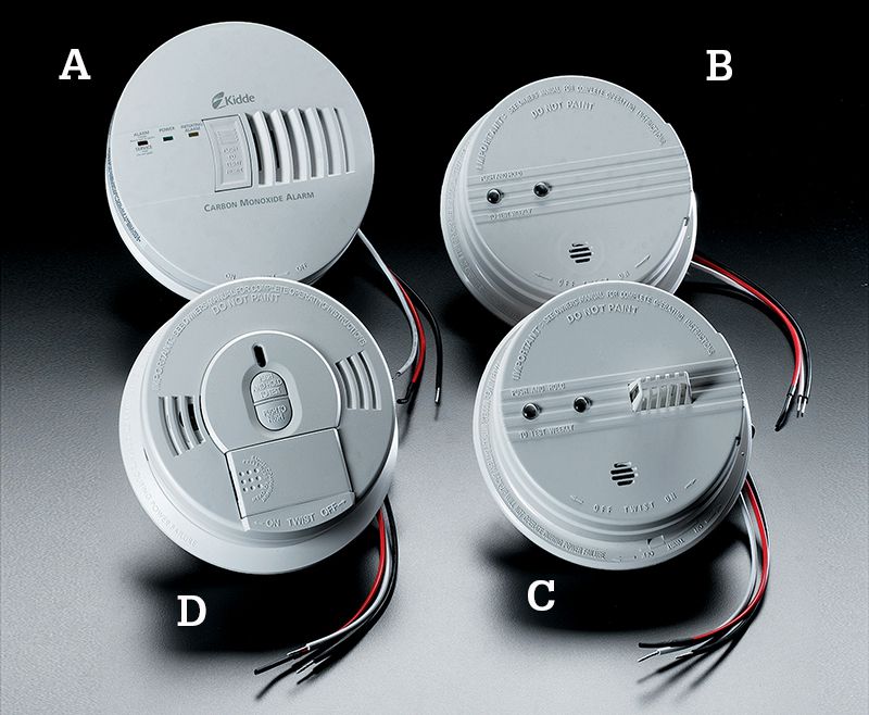
Smoke alarms and carbon monoxide (CO) alarms are required in new construction. Hard-wired CO alarms (A) are triggered by the presence of carbon monoxide gas. Smoke alarms are available in photoelectric and ionizing models. In ionizing detectors (B), a small amount of current flows in an ionization chamber. When smoke enters the chamber, it interrupts the current, triggering the alarm. Photoelectric alarms (C) rely on a beam of light, which when interrupted by smoke triggers an alarm. Heat alarms (D) sound an alarm when they detect areas of high heat in the room.
![]() How to Connect a Series of Hard-Wired Smoke Alarms
How to Connect a Series of Hard-Wired Smoke Alarms
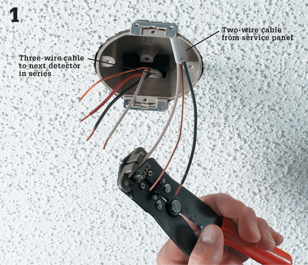
Pull 14/2 NM cable from the panel into the first ceiling electrical box in the smoke alarm series. Pull 14/3 NM cable between the remaining alarm outlet boxes. Use cable clamps to secure the cable in each outlet box. Remove sheathing, and strip insulation from wires.
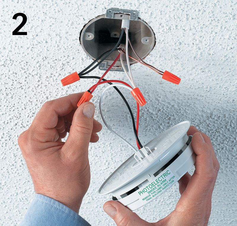
Ensure power is off, and test for power. Wire the first alarm in the series. Use a wire connector to connect the ground wires. Splice the black circuit wire with the alarm’s black lead and the black wire going to the next alarm in the series. Splice the white circuit wire with the alarm’s white wire and the white (neutral) wire going to the next alarm in the series. Splice the red traveler wire with the odd-colored alarm wire (in this case, also a red wire).
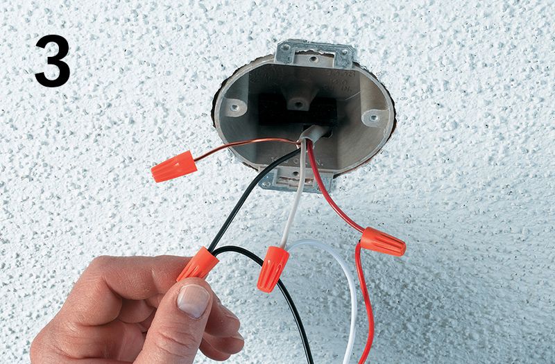
Wire the remaining alarms in the series by connecting the like-colored wires in each outlet box. Always connect the red traveler wire to the odd-colored (in this case, red) alarm wire. This red traveler wire connects all the alarms together so that when one alarm sounds, all the alarms sound. If the alarm doesn’t have a grounding wire, cap the ground with a wire connector. When all alarms are wired, install and connect the new 15-amp AFCI breaker.
![]() Landscape Lights
Landscape Lights
Some landscape lighting manufacturers pitch their systems as security products. If you keep the outside of your house well lit, the reasoning goes, the thieves will turn elsewhere to find easier pickings. It’s possible that the companies are right about this. But probably the stronger arguments are for improved safety and appearance.
It can’t be surprising that adding some light to the dark makes going places safer. This idea has been around for a long time—a very long time. But the notion that you can improve the look of your house by adding some nightlights is more recent. In fact, decorating with exterior lights became widespread only in the last 25 years, when low-voltage landscape lighting showed up.
Low-voltage lights are powered by a transformer that steps 120-volt current down to a safe 12 volts. Choosing the location for the transformer is an important part of planning. You have two options: inside the house and outside the house. The outside installation is a little easier, but the inside one is a little better, especially from a security standpoint. Also take some time to review your light placement. Once you are happy with the plan, drive a small stake where you want each light to go.
Tools & Materials ![]()
Drill/driver & bits
Hammer
Screwdrivers
Hacksaw
Spade
Low-voltage fixture
Wires
Transformer
Stakes
Hacksaw
Eye protection

Low-voltage lights are safe to install and use to beautify your outdoor spaces. Unlike solar landscape lights, they are powered by good old reliable electricity, so they really can stay on all night if you wish them to.
![]() Parts of a Landscape Light System
Parts of a Landscape Light System
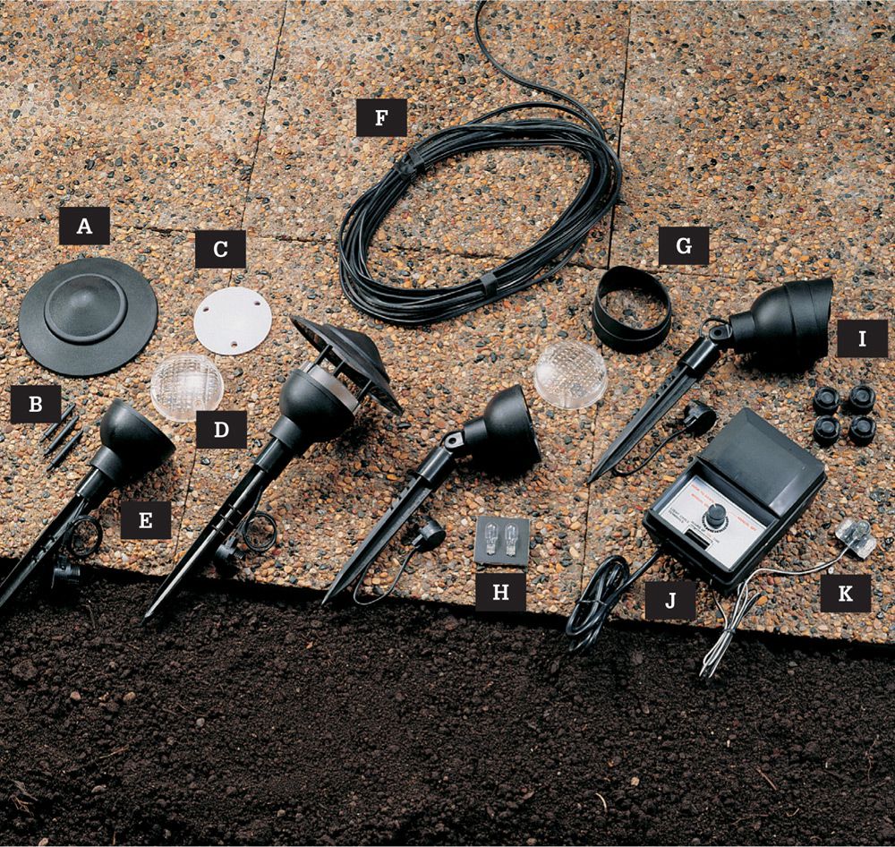
Landscape lighting can be ordered in kit form or as individual pieces. Kits include a few light heads, some wire, and a transformer that changes standard house current into low-voltage power. If you want half a dozen lights along the front walk, for example, then the kit is a good idea. It’s cheaper, very easy to install, and will last a long time unless the lights get run over by a lawnmower.
Typical low-voltage outdoor lighting systems consist of: lens cap (A), lens cap posts (B), upper reflector (C), lens (D), base/stake/cable connector assembly (contains lower reflector) (E), low-voltage cable (F), lens hood (G), 7-watt 12-volt bulbs (H), cable connector caps (I), control box containing transformer and timer (J), and light sensor (K).
![]() How To Modify Landscape Lights for Deck Installation
How To Modify Landscape Lights for Deck Installation
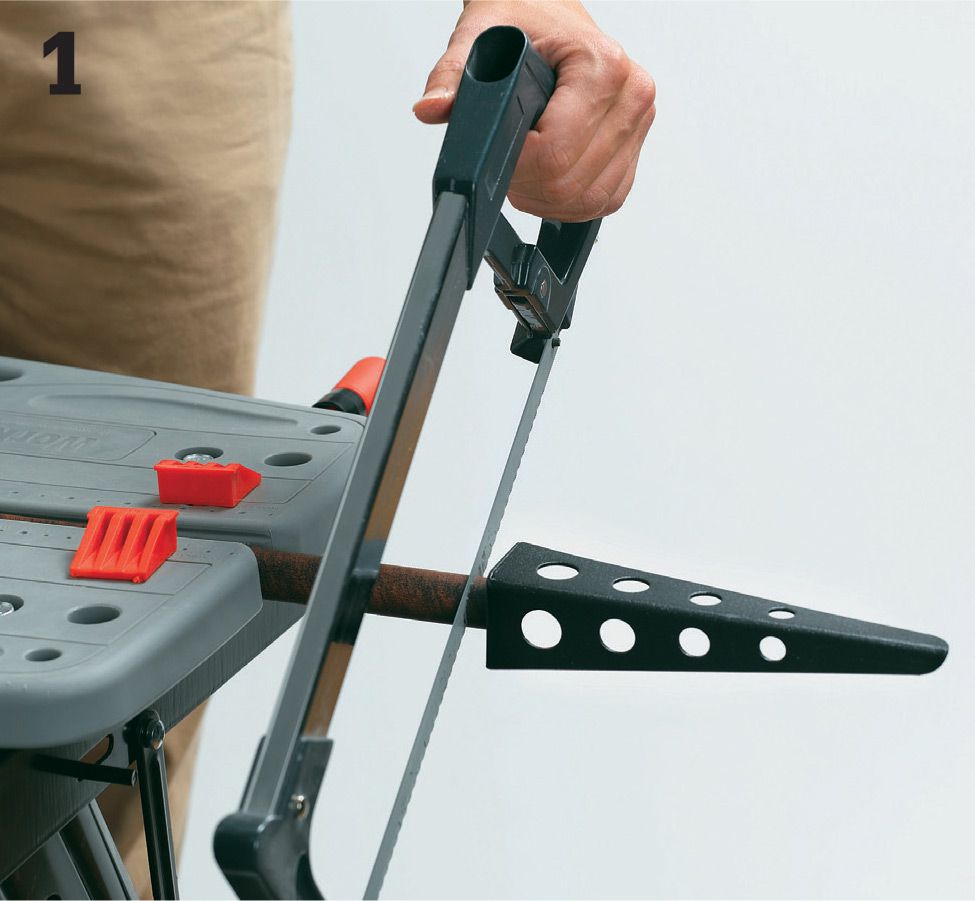
Specialty lights can cost a lot more than the standard plastic spike-base lamps. Because of this, many people modify the cheaper units to serve other purposes. To do this, first cut off the spike-base with a hacksaw.
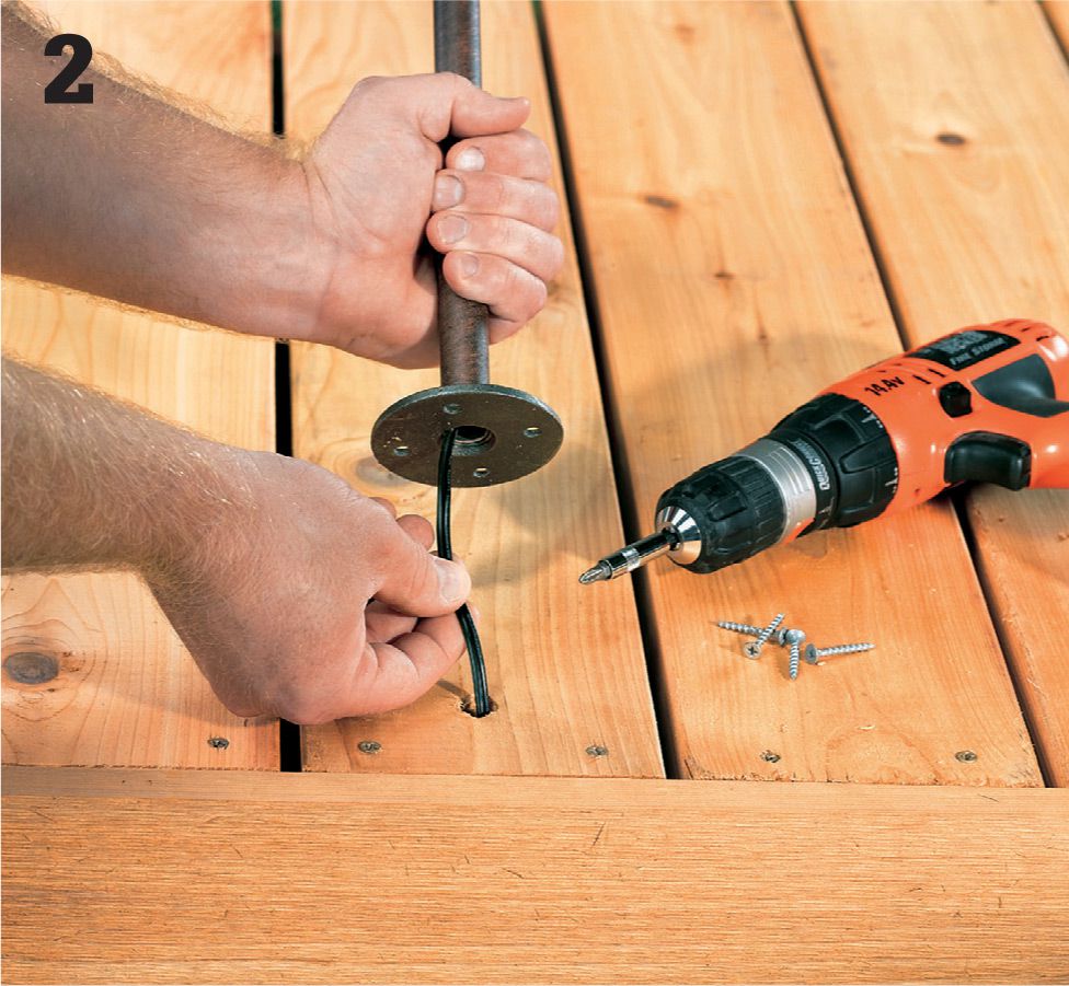
To install a modified light on a deck, bore a wire-clearance hole through a deck board. Then feed the low-voltage wire through this hole, and attach the base to the deck with screws. The same technique can be used to install modified units on planters or railings.
![]() How to Install Low-Voltage Landscape Lights
How to Install Low-Voltage Landscape Lights
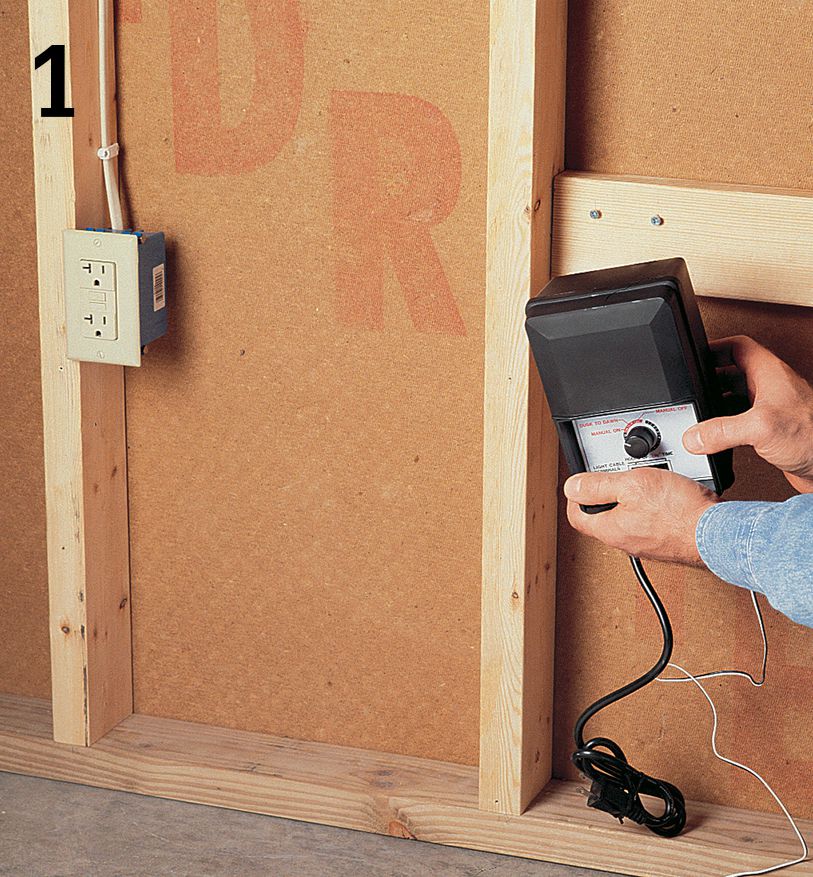
Install the transformers. In a garage, mount one on a wall within 24" of a GFCI receptacle and at least 12" off the floor. On an outdoor receptacle on a wall or a post, mount the transformer on the same post or an adjacent post at least 12" off the ground and not more than 24" from the receptacle.
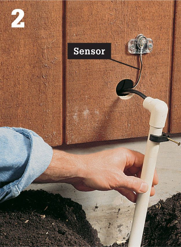
Drill a hole through the wall or rim joist for the low-voltage cable and any sensors to pass through. If a circuit begins in a high-traffic area, protect the cable by running it through a short piece of PVC pipe or conduit, and then into the shallow trench.
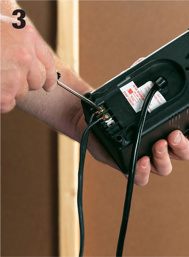
Attach the end of the low-voltage wire to the terminals on the transformer. Make sure that both strands of wire are held tightly by their terminal screws.
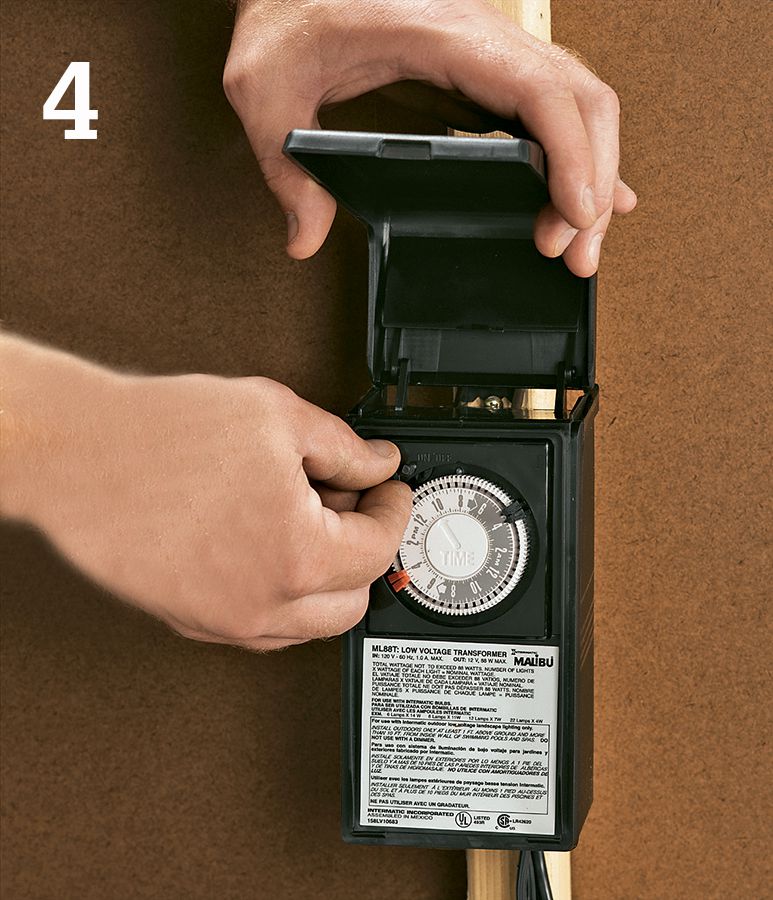
Transformers usually have a simple mechanism that allows you to set times for the lights to come ON and go OFF automatically. Set these times before hanging the transformer.
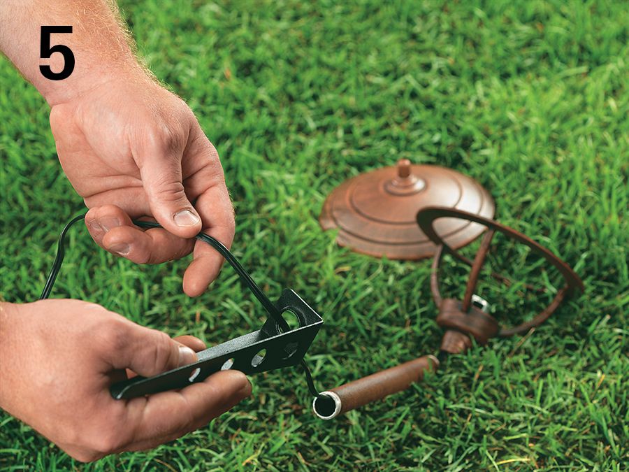
Many low-voltage light fixtures are modular, consisting of a spiked base, a riser tube, and a lamp. On these units, feed the wires and the wire connector from the light section down through the riser tube and into the base.
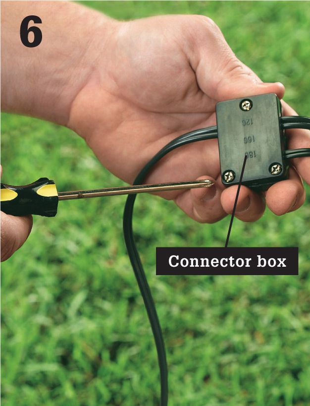
Take apart the connector box and insert the ends of the fixture wire and the low-voltage landscape cable into it. Puncture the wire ends with the connector box leads. Reassemble the connector box.
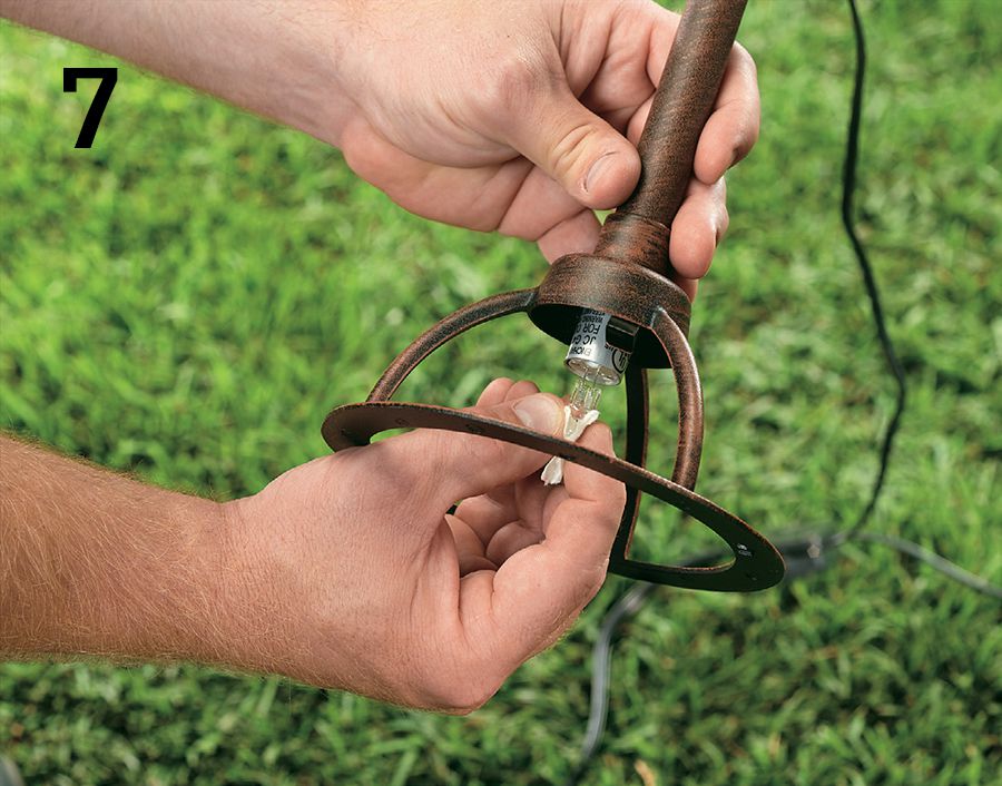
Feed the wire connector back into the light base, and attach it to the lampholder according to directions. Install the low-voltage light bulb.

Assemble the fixture parts that cover the bulb, including the lens cap and reflector or the cap.

Lay out the lights, with the wires attached, in the pattern you have chosen. Then cut the sod between fixtures with a spade. Push the blade at least 6" deep and pry open a seam by rocking the blade back and forth.
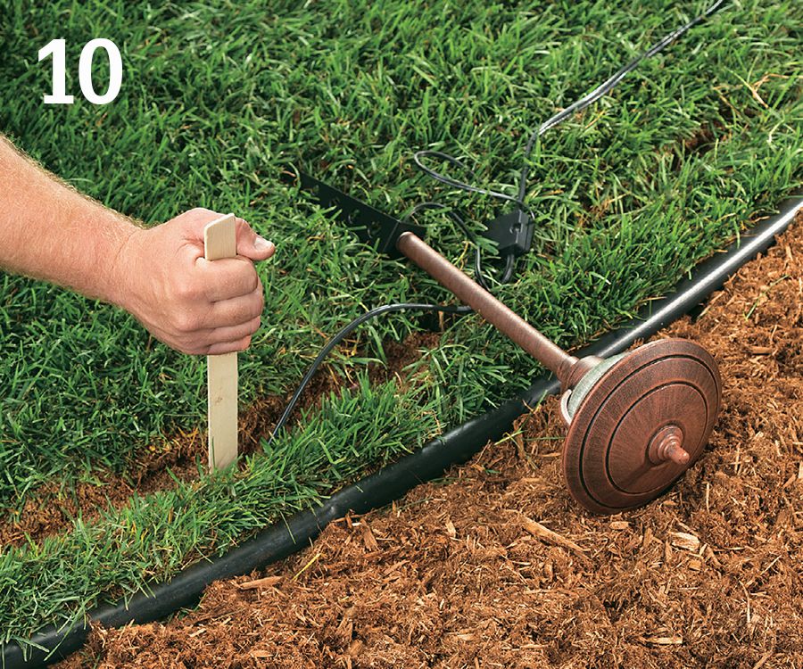
Gently force the cable into the slot formed by the spade; don’t tear the wire insulation. A paint stick (or a cedar shingle) is a good tool for this job. Push the wire to the bottom of the slot.

Firmly push the light into the slot in the sod. If the lamp doesn’t seat properly, pull it out and cut another slot at a right angle to the first, and try again.
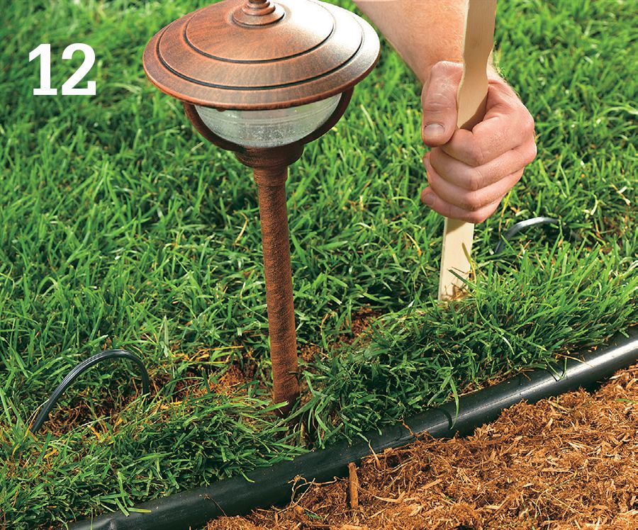
Once the lamp is stabilized, tuck any extra wire into the slot using the paint stick. No part of the wire should be exposed when you are done with the job.
![]() Doorbells
Doorbells
Most doorbell problems are caused by loose wire connections or worn-out switches. Reconnecting loose wires or replacing a switch requires only a few minutes. Doorbell problems also can occur if the chime unit becomes dirty or worn or if the low-voltage transformer burns out. Both parts are easy to replace. Because doorbells operate at low voltage, the switches and the chime unit can be serviced without turning off power to the system. However, when replacing a transformer, always turn off the power at the main service panel.
Some older houses have other low-voltage transformers in addition to the doorbell transformer. These transformers control heating and air-conditioning thermostats (see page 224 to 227) or other low-voltage systems. When testing and repairing a doorbell system, it is important to identify the correct transformer. A doorbell transformer has a rating of 24 volts or less. This rating is printed on the face of the transformer. The location of your doorbell transformer is based on local custom and the age of your home. It may be near or attached to the service panel. It may be in the attic, basement, crawlspace, or garage.
In most modern heating and air-conditioning systems, the transformer serving the system is inside the furnace cabinet. In older systems, it may be located near the furnace.
Occasionally, a doorbell problem is caused by a broken low-voltage wire somewhere in the system. You can test for wire breaks with a battery-operated multitester. If the test indicates a break, new low-voltage wires must be installed between the transformer and the switches or between the switches and chime unit. Replacing low-voltage wires is not a difficult job, but it can be time-consuming. You may choose to have an electrician do this work.
Tools & Materials ![]()
Continuity tester
Screwdriver
Multimeter
Needlenose pliers
Cotton swab
Rubbing alcohol
Replacement doorbell switch (if needed)
Masking tape
Replacement chime unit (if needed)
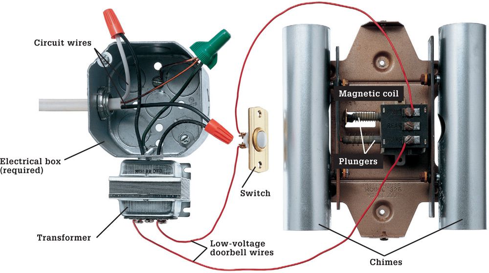
A home doorbell system is powered by a transformer that reduces 120-volts to 24 volts or less. Current flows from the transformer to one or more push-button switches. When pushed, the switch activates a magnetic coil inside the chime unit, causing a plunger to strike a musical tuning bar.
![]() How to Test a Nonfunctional Doorbell System
How to Test a Nonfunctional Doorbell System
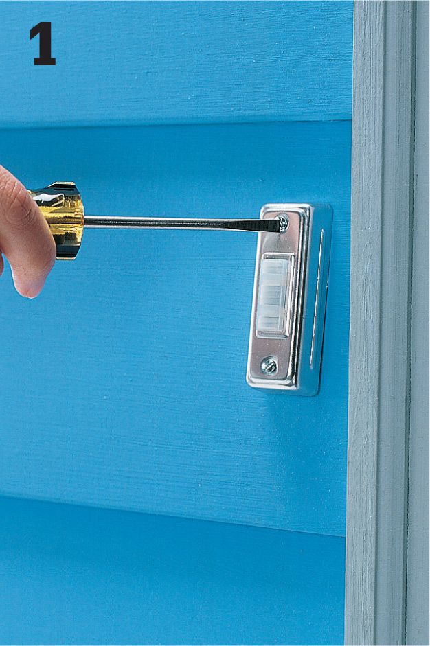
Remove the mounting screws holding the doorbell switch to the siding.
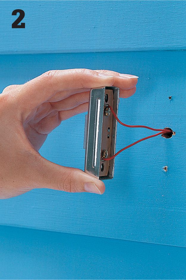
Carefully pull the switch away from the wall.
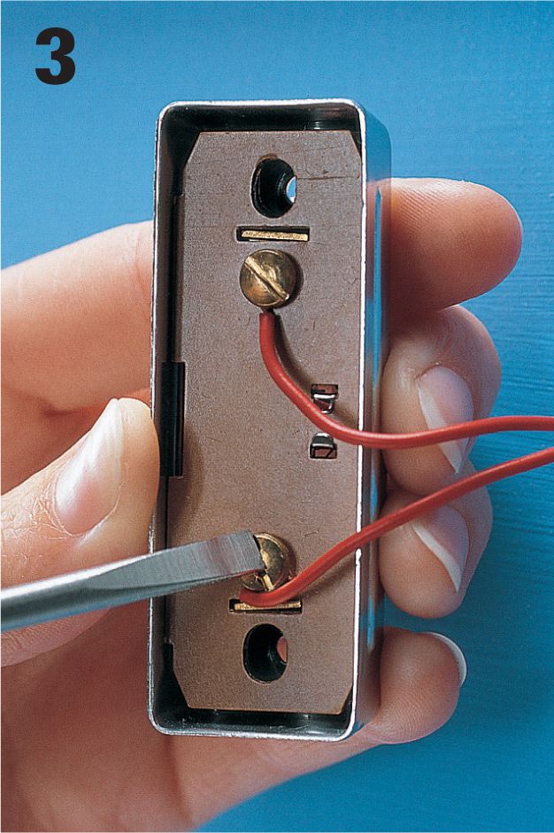
Inspect wire connections on the switch. If wires are loose, reconnect them to the screw terminals. Test the doorbell by pressing the button. If the doorbell still does not work, disconnect the switch and test it with a continuity tester.
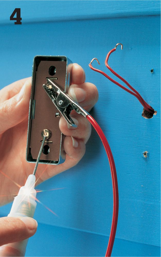
Attach the clip of a continuity tester to one screw terminal and touch the probe to the other screw terminal. Press the switch button. The tester should glow. If not, then the switch is faulty and must be replaced.
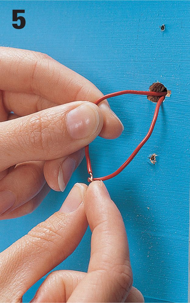
Twist the doorbell switch wires together temporarily to test the other parts of the doorbell system.
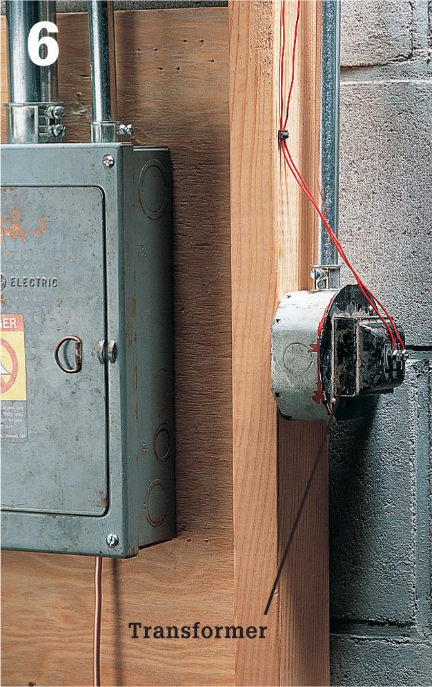
Locate the doorbell transformer. If it’s not near the service panel, look in the garage, crawlspace, and attic.
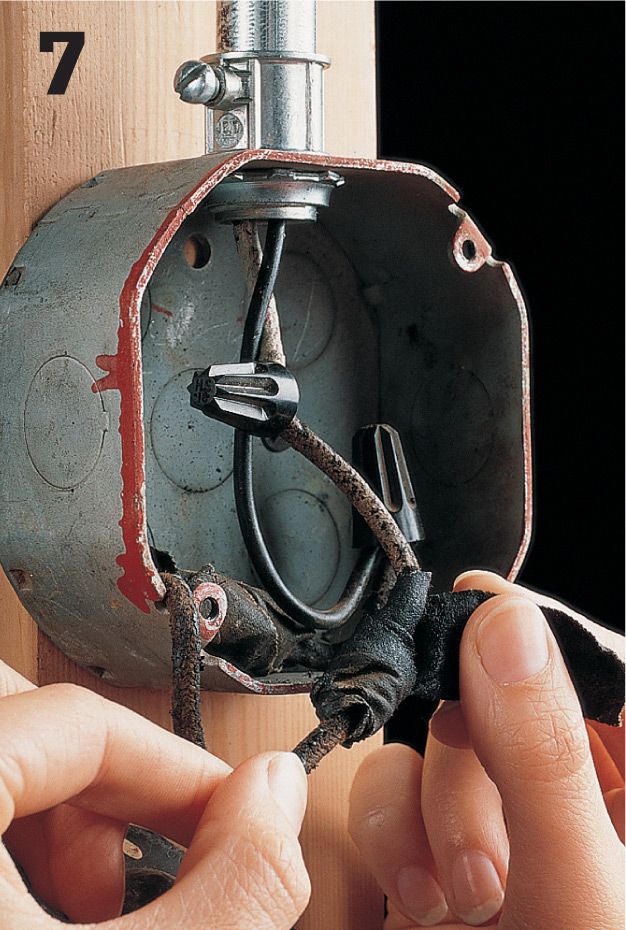
Identify the doorbell transformer by reading its voltage rating. Doorbell transformers have a voltage rating of 24 volts or less. Turn off power to the transformer at the main service panel. Remove the cover on the electrical box, and test wires for power. Reconnect any loose wires. Replace taped connections with wire connectors.
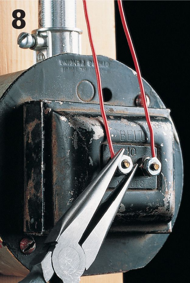
Reattach the cover plate. Inspect the low-voltage wire connections, and reconnect any loose wires using needlenose pliers or a screwdriver. Turn on power to the transformer at the main service panel.
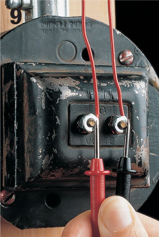
Touch the probes of the multitester to the low-voltage screw terminals on the transformer. If the transformer is operating properly, the meter will detect power within 2 volts of the transformer’s rating. If not, the transformer is faulty and must be replaced.
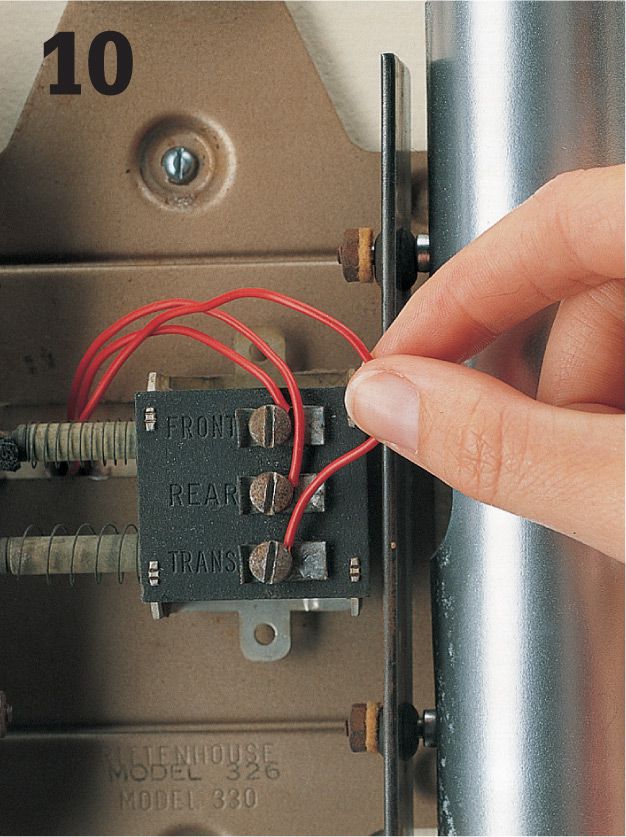
Test the chime unit. Remove the cover plate on the doorbell chime unit. Inspect the low-voltage wire connections, and reconnect any loose wires.
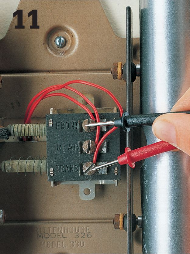
Test that the chime unit is receiving current. Touch probes of a multimeter to screw terminals. If the multimeter detects power within 2 volts of the transformer rating, then the unit is receiving proper current. If it detects no power or very low power, there is a break in the low-voltage wiring, and new wires must be installed.
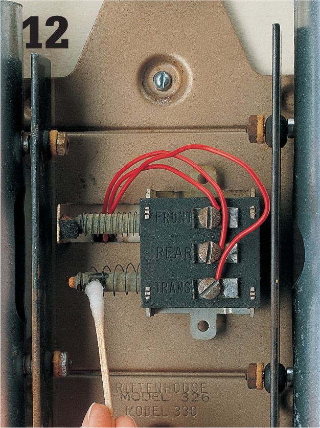
Clean the chime plungers (some models) with a cotton swab dipped in rubbing alcohol. Reassemble doorbell switches, and then test the system by pushing one of the switches. If the doorbell still does not work, then the chime unit is faulty and must be replaced (see page 223).
![]() How to Replace a Doorbell Switch
How to Replace a Doorbell Switch
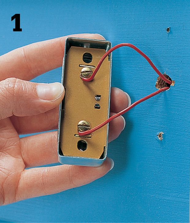
Remove the doorbell switch mounting screws, and carefully pull the switch away from the wall.
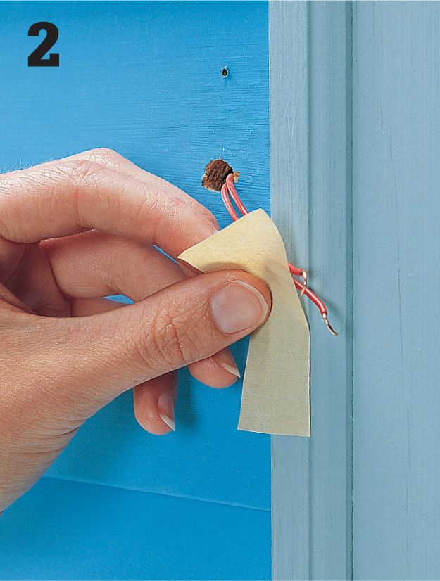
Disconnect wires from the switch. Tape wires to the wall to prevent them from slipping into the wall cavity.
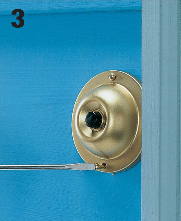
Purchase a new doorbell switch, and connect the wires to the screw terminals on the new switch. (Wires are interchangeable and can be connected to either terminal.) Anchor the switch to the wall.
![]() How to Replace a Doorbell Chime Unit
How to Replace a Doorbell Chime Unit
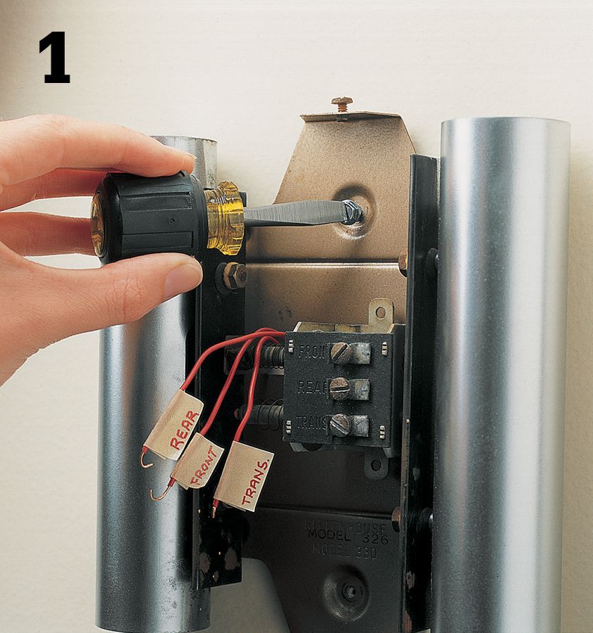
Turn off power to the doorbell at the main panel. Remove the cover plate from the old chime. Label the low-voltage wires FRONT, REAR, or TRANS to identify their screw terminal locations. Disconnect the wires. Remove the old chime unit.
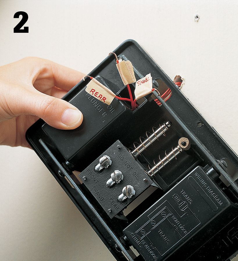
Purchase a new chime unit that matches the voltage rating of the old unit. Thread the low-voltage wires through the base of the new chime unit. Attach the chime unit to the wall using the mounting screws included with the installation kit.
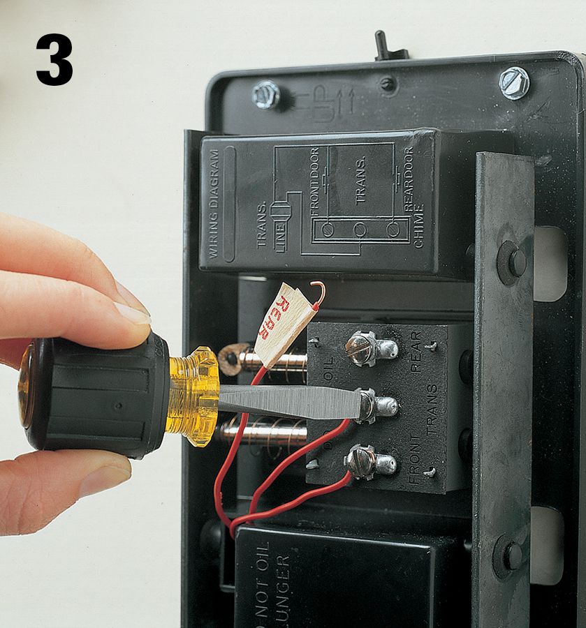
Connect the low-voltage wires to the screw terminals on the new chime unit. Attach the cover plate, and turn on the power at the main service panel.
![]() Programmable Thermostats
Programmable Thermostats
Athermostat is a temperature-sensitive switch that automatically controls home heating and air-conditioning systems. There are two types of thermostats. Low-voltage thermostats control whole-house heating and air conditioning from one central location. Line-voltage thermostats are used in zone heating systems, where each room has its own heating unit and thermostat.
A low-voltage thermostat is powered by a transformer (usually located inside the furnace) that reduces 120-volt current to about 24 volts. A low-voltage thermostat is very durable, but failures can occur if wire connections become loose or dirty, if thermostat parts become corroded, or if a transformer wears out. Some thermostat systems have two transformers. One transformer controls the heating unit, and the other controls the air-conditioning unit.
Line-voltage thermostats are powered by the same circuit as the heating unit, usually a 240-volt circuit. Always make sure to turn off the power before servicing a line-voltage thermostat (typically, these are found in electric heaters).
A thermostat can be replaced in about one hour. Many homeowners choose to replace standard low-voltage or line-voltage thermostats with programmable setback thermostats. These programmable thermostats can cut energy use by up to 35 percent.
When buying a new thermostat, make sure the new unit is compatible with your heating/air-conditioning system. For example, a thermostat intended for a furnace and air conditioner may not work with a heat pump. For reference, take along the brand name and model number of the old thermostat and of your heating/air-conditioning units. When buying a new low-voltage transformer, choose a replacement with voltage and amperage ratings that match the old thermostat.
Tools & Materials ![]()
Screwdriver
Masking tape
New thermostat
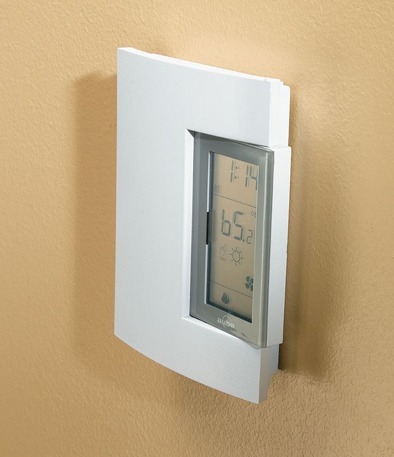
A programmable thermostat allows you to significantly reduce your energy consumption by taking greater control over your heating and cooling system.
![]() Traditional Low-Voltage Thermostats
Traditional Low-Voltage Thermostats
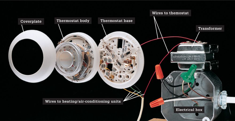
Low-voltage thermostat systems have a transformer that is either connected to an electrical junction box or mounted inside a furnace access panel. Very thin wires (18 to 22 gauge) send current to the thermostat. The thermostat constantly monitors room temperatures and sends electrical signals to the heating/cooling unit through additional wires. The number of wires connected to the thermostat varies from two to six, depending on the type of heating/air-conditioning system. In the common four-wire system shown above, power is supplied to the thermostat through a single wire attached to screw terminal R. Wires attached to other screw terminals relay signals to the furnace heating unit, the air-conditioning unit, and the blower unit. Before removing a thermostat, make sure to label each wire to identify its screw terminal location.
![]() Programmable Thermostats
Programmable Thermostats
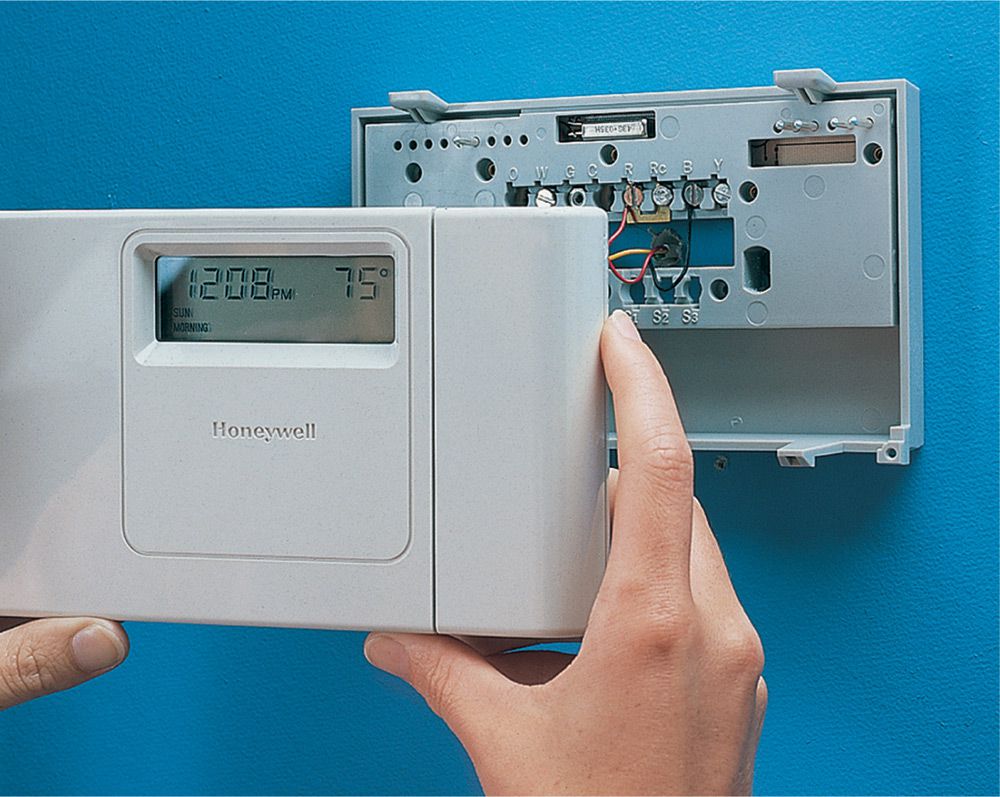
Programmable thermostats contain sophisticated circuitry that allows you to set the heating and cooling systems in your house to adjust automatically at set times of the day. Replacing a manual thermostat with a programmable model is a relatively simple job that can have big payback on heating and cooling energy savings.
![]() How to Upgrade to a Programmable Thermostat
How to Upgrade to a Programmable Thermostat
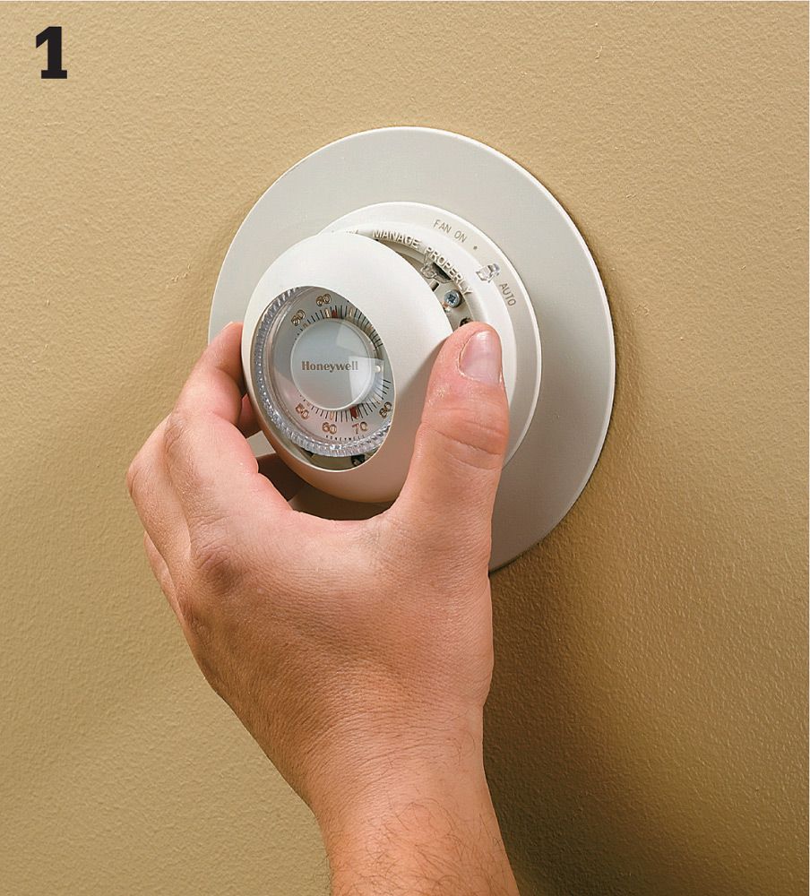
Start by removing the existing thermostat. Turn off the power to the furnace at the main service panel, and test for power. Then remove the thermostat cover.
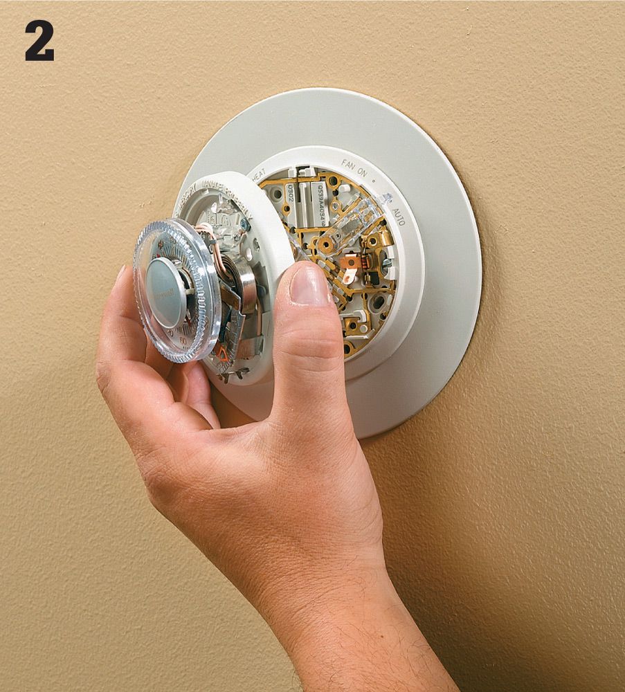
The body of the thermostat is held to a wall plate with screws. Remove these screws, and pull the body away from the wall plate. Set the body aside.
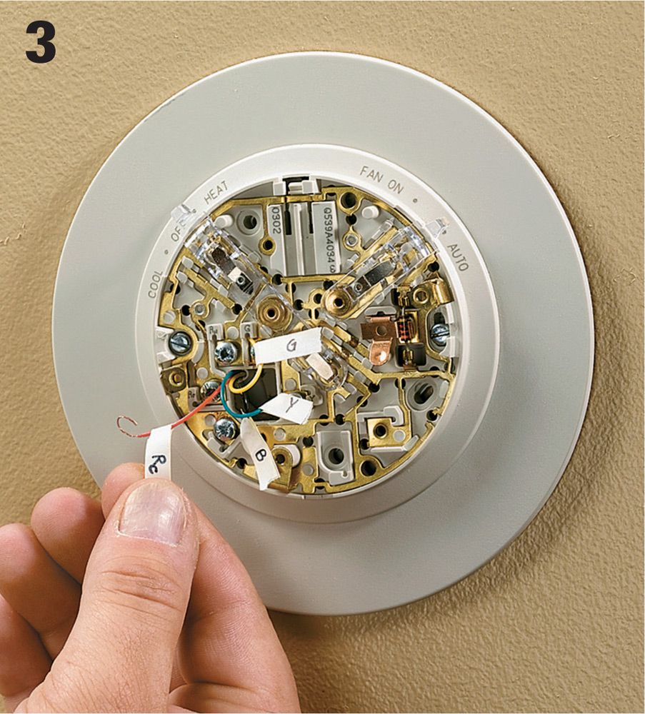
The low-voltage wires that power the thermostat are held by screw terminals to the mounting plate. Do not remove the wires until you label them with tape according to the letter printed on the terminal to which each wire is attached.
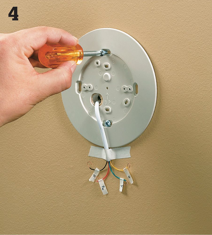
Once all the wires are labeled and removed from the mounting plate, tape the cable that holds these wires to the wall to keep it from falling back into the wall. Then unscrew the mounting plate and set it aside.
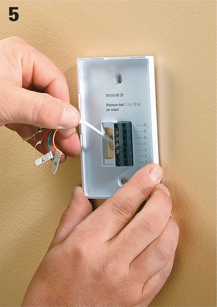
Position the new thermostat base on the wall, and guide the wires through the central opening. Screw the base to the wall using wall anchors if necessary.
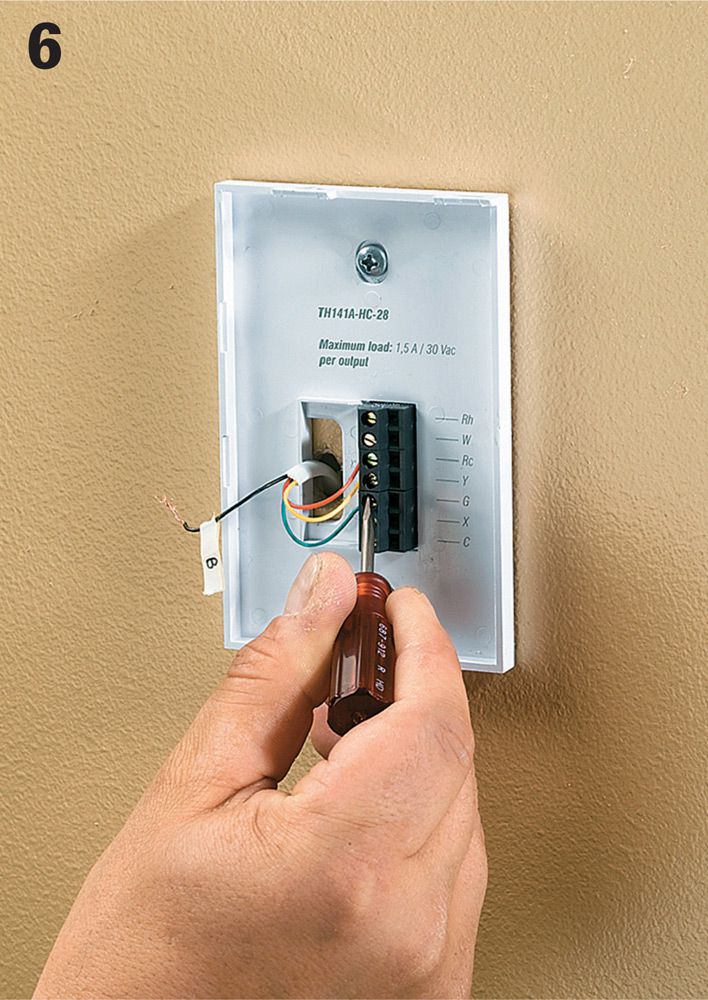
Check the manufacturer’s instructions to establish the correct terminal for each low-voltage wire. Then connect the wires to these terminals, making sure each screw is secure.
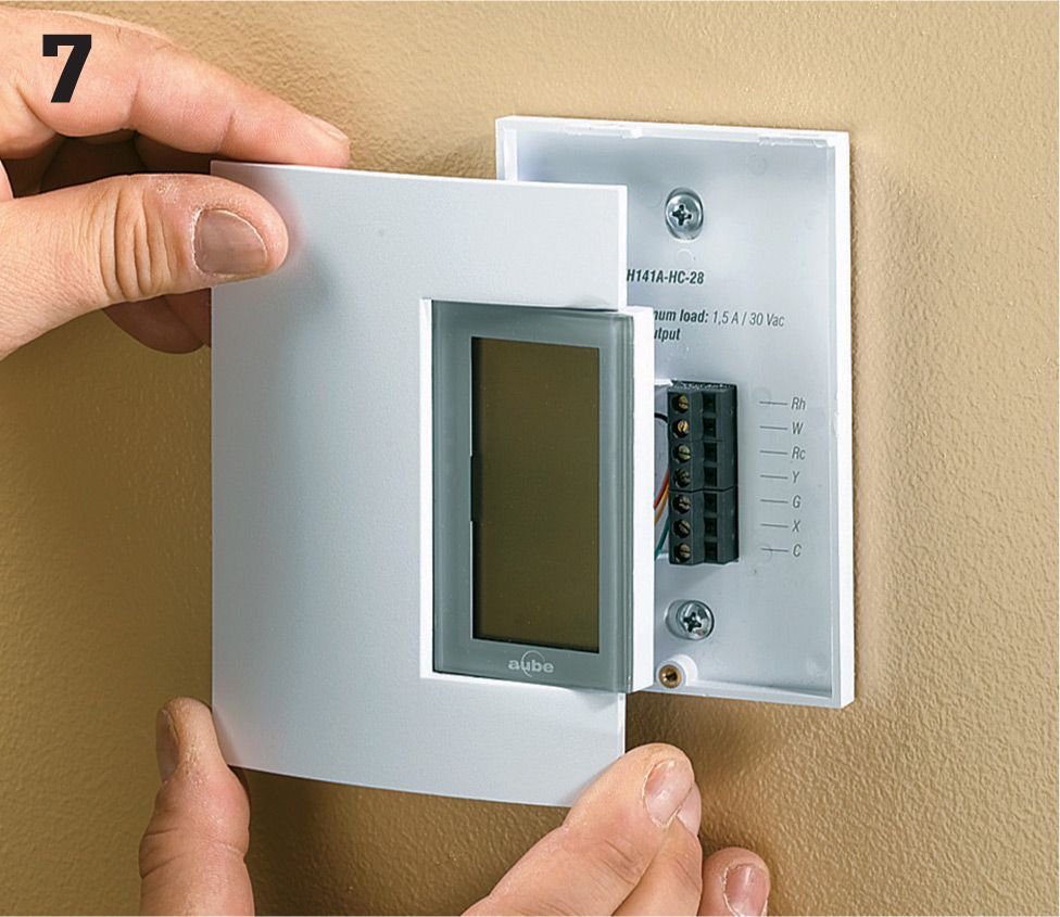
Programmable thermostats require batteries to store the programs so they won’t disappear if the power goes out in a storm. Make sure to install batteries before you snap the thermostat cover in place. Program the new unit to fit your needs, and then turn on the power to the furnace.
Mercury Thermostats ![]()
Older model thermostats (and even a few still being made today) often contained one or more small vials of mercury totaling 3 to 4 grams in weight. Because mercury is a highly toxic metal that can cause nerve damage in humans, along with other environmental problems, DO NOT dispose of an old mercury thermostat with your household waste. Instead, bring it to a hazardous waste disposal site or a mercury recycling site if your area has one (check with your local solid waste disposal agency). The best way to determine if your old thermostat contains mercury is simply to remove the cover and look for the small glass vials or ampules containing the silverfish mercury substance. If you are unsure, it is always better to be safe and keep the device in question out of the normal waste stream.
![]() Wireless Switches
Wireless Switches
Sometimes a light switch is just in the wrong place, or it would be more convenient to have two switches controlling a single fixture. Adding a second switch the conventional way generally requires hours of work and big holes in walls. (Electricians call this a three-way switch installation.) Fortunately wireless switch kits are available to perform basically the same function for a fraction of the cost and effort. There is a bit of real wiring involved here, but it’s not nearly as complicated as the traditional method of adding a three-way switch installation.
The kits work by replacing a conventional switch with a unit that has a built-in radio frequency receiver that will read a remote device mounted within a 50-ft. radius. The kits come with a remote, battery-powered switch (it looks like a standard light switch) that you can attach to a wall with double-sided tape.
Two other similar types of wireless switch kits are also available. One allows you to control a plugged-in lamp or appliance with a remote light switch. The second type allows you to control a conventional light fixture remotely, but instead of replacing the switch, the receiver screws in below the light bulb. This is particularly useful if you want to control a pull-chain light from a wall switch.
Tools & Materials ![]()
Voltage sensor
Screwdrivers
Wire connectors
Wireless switch transmitter & receiver/switch
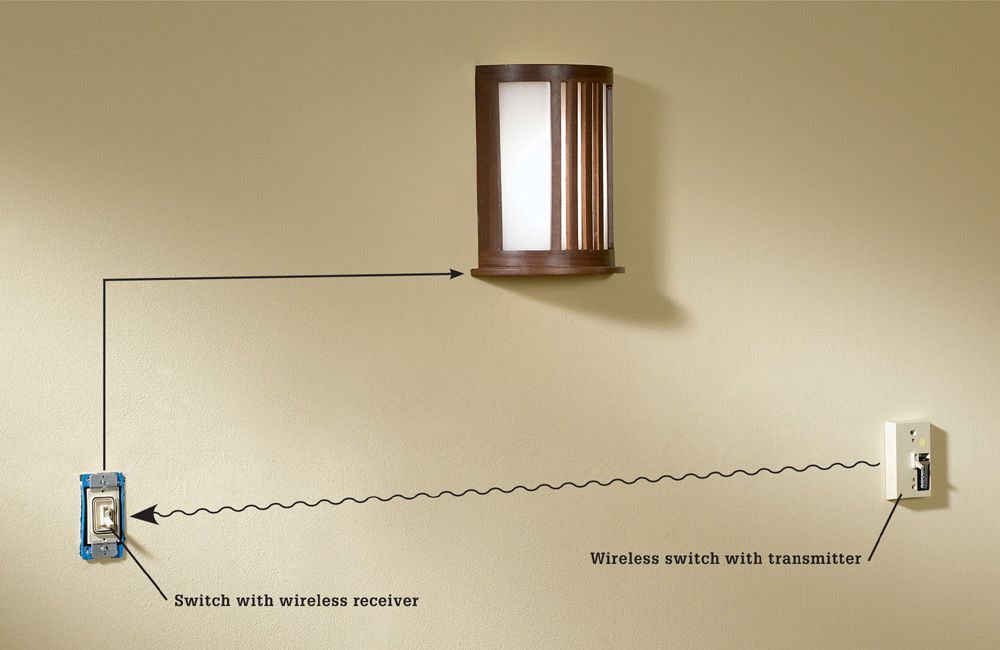
A wireless switch is a two-part switching system: a wireless switch with a battery-powered transmitter can be attached to any wall surface; an existing switch is then replaced with a new switch containing a receiver that is triggered by signals from the wireless transmitter, effectively creating a three-way switch condition.
Wireless Switch Products ![]()
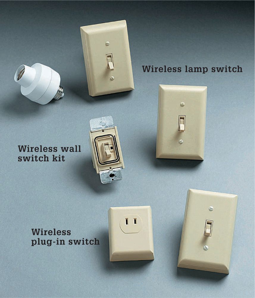
Wireless kits are available to let you switch lights on and off remotely in a variety of ways: at the switch, at the plug, or at the bulb socket.
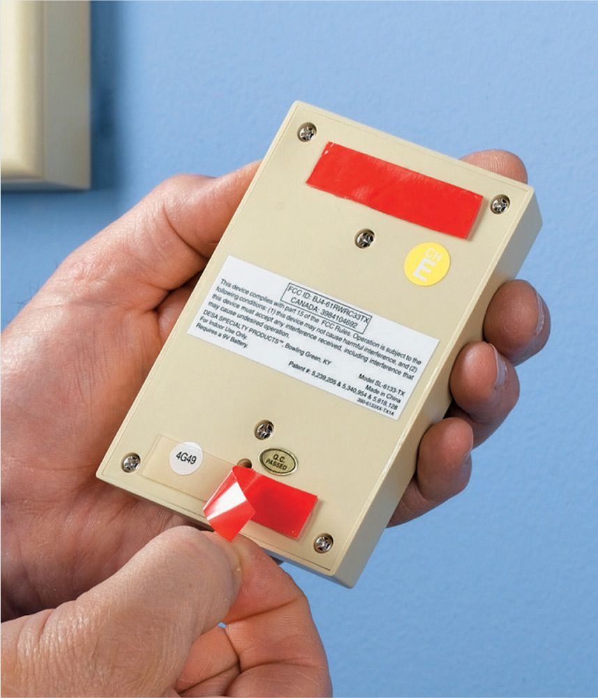
The remote switch is a wireless transmitter that requires a battery. The transmitter switch attaches to the wall with adhesive tape or velcro strips.
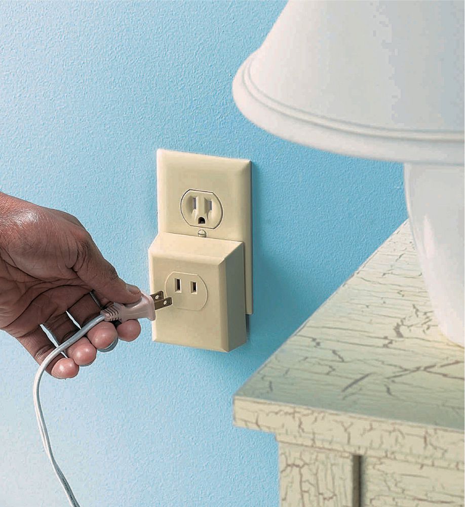
A receiver with a receptacle can be plugged into any receptacle to give it wireless functionality. The switch is operated with a remote control transmitter.
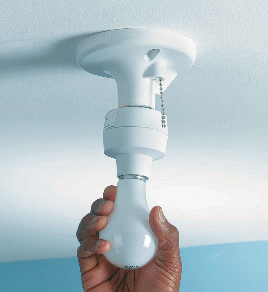
A radio-controlled light fixture can be threaded into the socket of any existing light fixture so it can be turned on and off with a remote control device.
![]() How To Install a Wireless Wall Switch
How To Install a Wireless Wall Switch
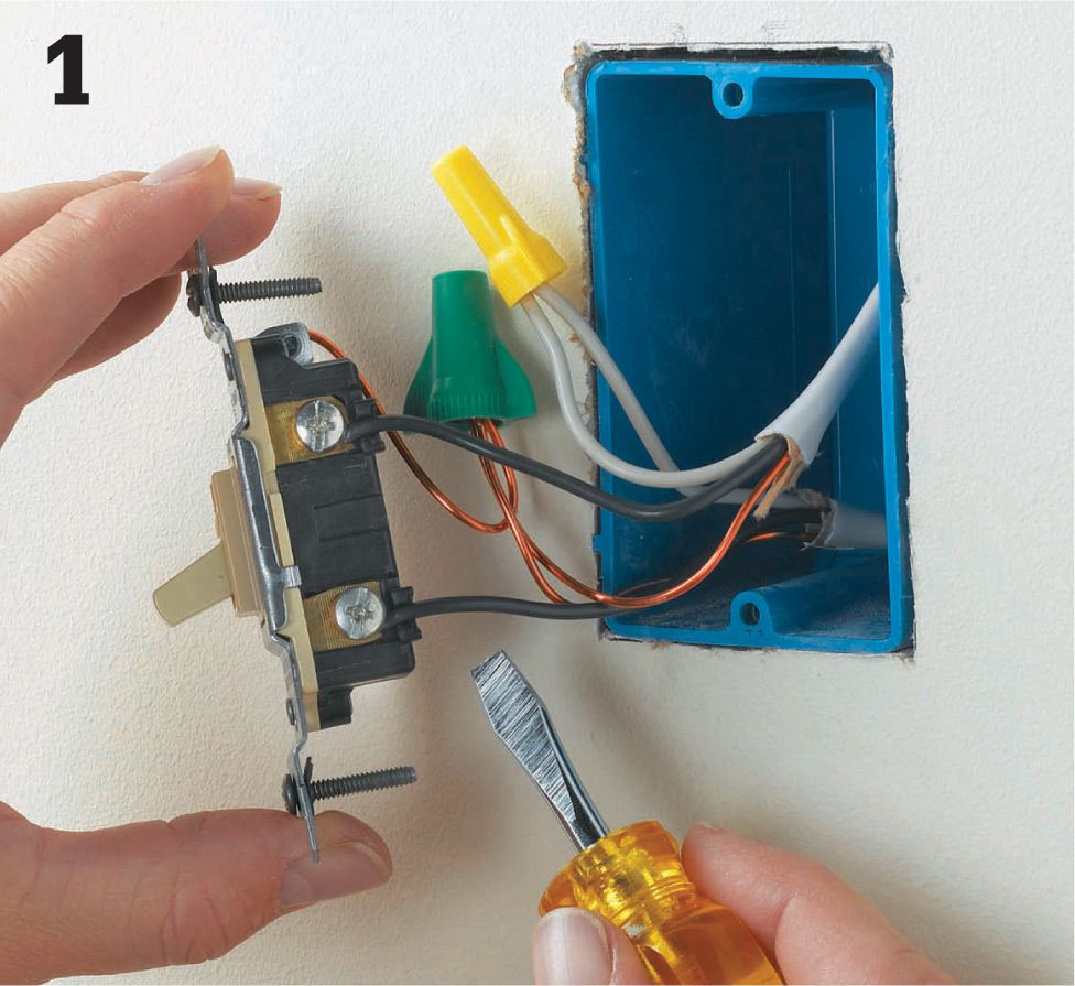
Get rid of the old switch. Shut off power to the switch circuit, and then disconnect and remove the old switch.
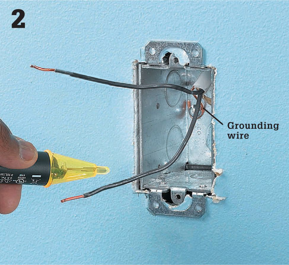
Identify the lead wire. Carefully separate the power supply wires (any color but white or green) in the switch box so they are not contacting each other or any other surface. Restore power and test each lead wire with a sensor to identify which wire carries the power (the LINE) and which is headed for the fixture the switch controls (the LOAD). Shut power back off, and then label the wires.
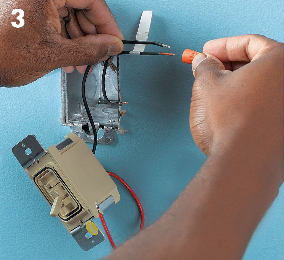
Connect the LINE wire to the LINE terminal or wire on the switch. Connect the LOAD wire (or wires) to the LOAD terminal or wire. The neutral whites (if present) and green grounding wires should be twisted together with a connector. The greens should be grounded to the grounding clip or terminal in the box. Note: Some switch boxes, such as the one above, are wired with NM2 cable that has two blacks and a green wire and no white.
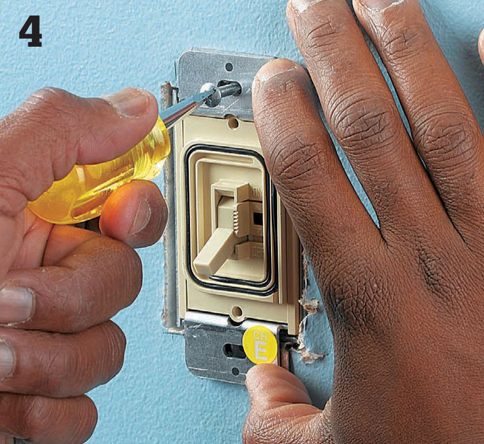
Once the wires are firmly connected, you can attach the switch to the box. Tuck the new switch and wires neatly back into the box. Then drive the two long screws that are attached to the new switch into the two holes in the electrical box.
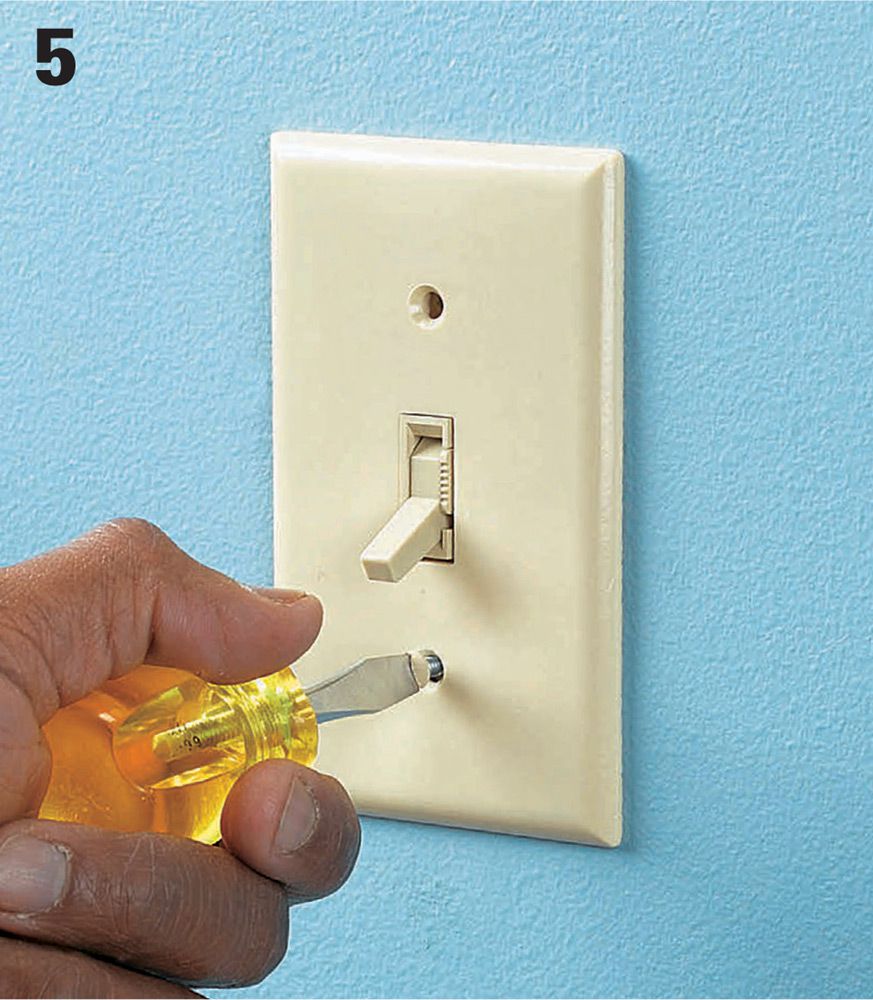
Attach the cover plate to the new wireless switch. Turn the power service back on, and test to make sure the switch operates normally.
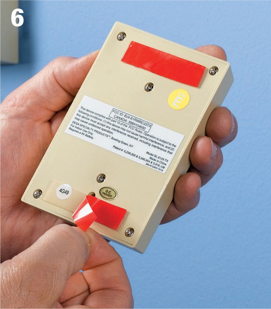
Remove the backing from the adhesive pads on the back of the wireless switch transmitter box. Install a new 9-volt battery (or other type as required) in the box, and connect it to the switch transmitter terminals.
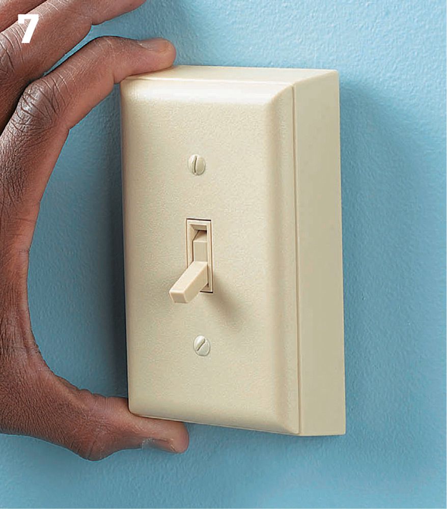
Stick the transmitter box to the wall at the desired location. The box should be no more than 50 ft. from the receiver switch (see manufacturer’s suggestions). The box should be at the same height (usually 48") as the other switch boxes.
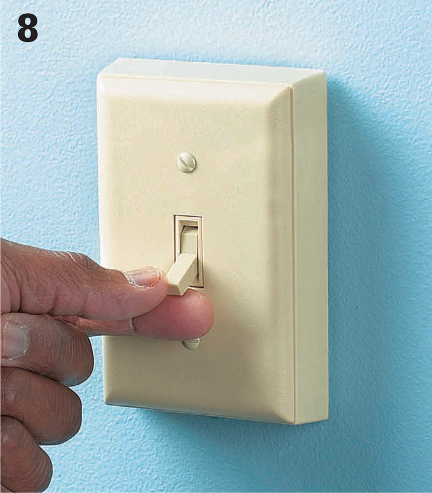
Test the operation of both switches. Each switch should successfully turn the light fixture on and off. You’ve just successfully created a three-way switch installation without running any new wires.
![]() Baseboard Heaters
Baseboard Heaters
Baseboard heaters are a popular way to provide additional heating for an existing room or primary heat to a converted attic or basement.
Heaters are generally wired on a dedicated 240-volt circuit controlled by a thermostat. Several heaters can be wired in parallel and controlled by a single thermostat (see circuit map 15, page 157).
Baseboard heaters are generally surface-mounted without boxes, so in a remodeling situation, you only need to run cables before installing wallboard. Be sure to mark cable locations on the floor before installing drywall. Retrofit installations are also not difficult. You can remove existing baseboard and run new cable in the space behind. Baseboard heaters (and other heating equipment) get very hot and can ignite nearby combustible materials. Maintain the manufacturers recommended distance between the heater and materials such as curtains, blinds, and wood.
Tools & Materials ![]()
Drill/driver
Wire stripper
Cable ripper
Wallboard saw
Baseboard heater or heaters
240-thermostat (in-heater or in-wall)
12/2 NM cable
Electrical tape
Basic wiring supplies
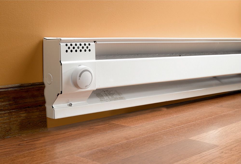
Baseboard heaters can provide primary or supplemental heat for existing rooms or additions. Install heaters with clear space between the heater and the floor.
![]() Baseboard Thermostats
Baseboard Thermostats
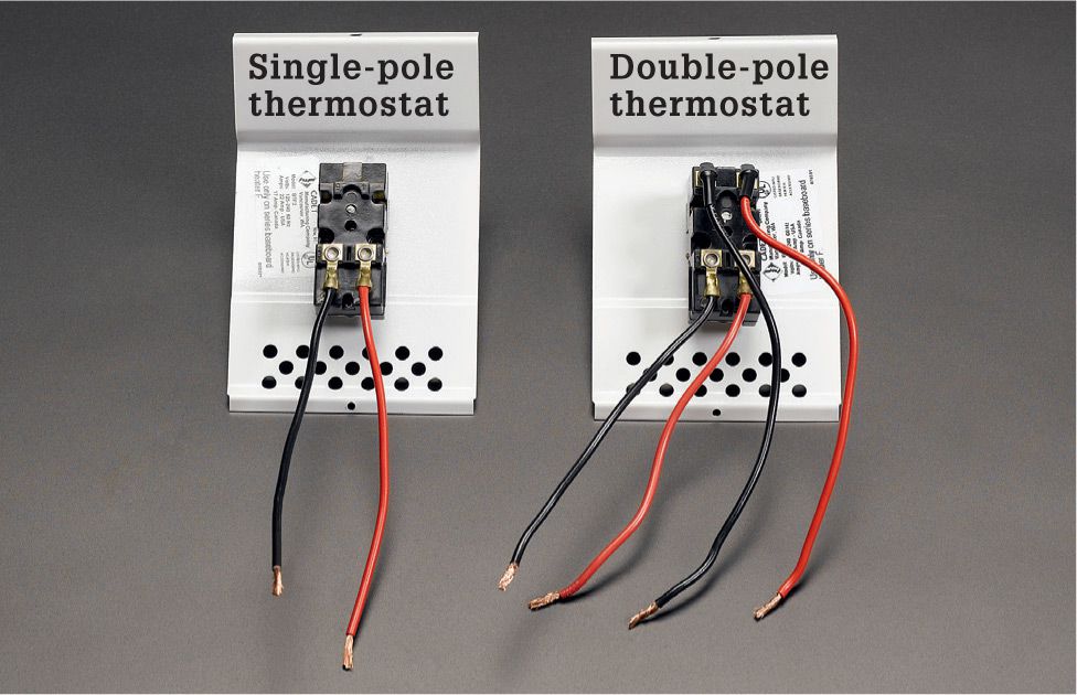
Single-pole and double-pole thermostats work in a similar manner, but double-pole models are safer. The single-pole model will open the circuit (causing shutoff) in only one leg of the power service. Double-pole models have two sets of wires to open both legs, lessening the chance that a person servicing the heater will contact a live wire.
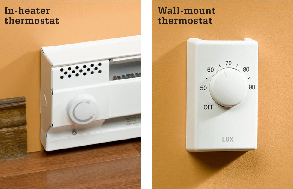
In-heater and wall-mount are the two types of baseboard thermostats you can choose from. If you are installing multiple heaters, a single wall-mount thermostat is more convenient. Individual in-heater thermostats give you more zone control, which can result in energy savings.
How Much Heater Do You Need ![]()
If you don’t mind doing a little math, determining how many lineal feet of baseboard heater a room requires is not hard.
1. Measure the area of the room in square feet (length × width):_________
2. Multiply the area by 10 to get the baseline minimum wattage:_________
3. Add 5% for each newer window or 10% for each older window:_________
4. Add 10% for each exterior wall in the room:_________
5. Add 10% for each exterior door:_________
6. Add 10% if the space below is not insulated:_________
7. Add 20% if the space above is not well insulated:_________
8. Add 10% if ceiling is more than 8 ft. high:_________
9. Total of the baseline wattage plus all additions:_________
10. Divide this number by 250 (the wattage produced per foot of standard baseboard heater):_________
11. Round up to a whole number. This is the minimum number of feet of heater you need._________
Note: It is much better to have more feet of heater than is required than fewer. Having more footage of heater does not consume more energy; it does allow the heaters to work more efficiently.
Planning Tips for Baseboard Heaters ![]()
✵ Baseboard heaters require a dedicated circuit. A 20-amp, 240-volt circuit of 12-gauge copper wire will power up to 16 ft. of heater.
✵ Do not install a heater beneath a wall receptacle. Cords hanging down from the receptacle are a fire hazard.
✵ Do not mount heaters directly on the floor. You should maintain at least 1" of clear space between the baseboard heater and the floor covering.
✵ Installing heaters directly beneath windows is a good practice.
✵ Locate wall thermostats on interior walls only, and do not install directly above a heat source.
![]() How to Install a 240-Volt Baseboard Heater
How to Install a 240-Volt Baseboard Heater
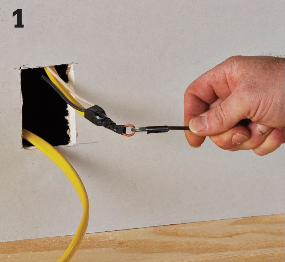
At the heater locations, cut a small hole in the drywall 3" to 4" above the floor. Pull 12/2 NM cables through the first hole: one from the thermostat, the other to the next heater. Pull all the cables for subsequent heaters. Middle-of-run heaters will have two cables, while end-of-run heaters have only one cable. (See also circuit map 15, page 157.)
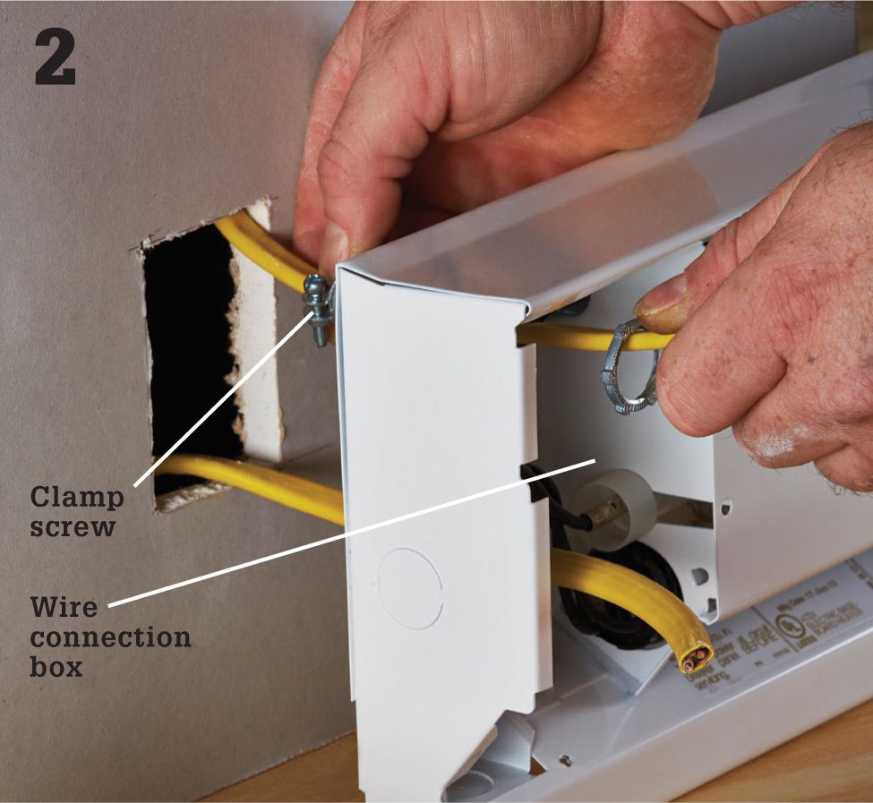
Remove the cover on the wire connection box. Open a knockout for each cable that will enter the box, and then feed the cables through the cable clamps and into the wire connection box. Attach the clamps to the wire connection box, and tighten the clamp screws until the cables are gripped firmly.
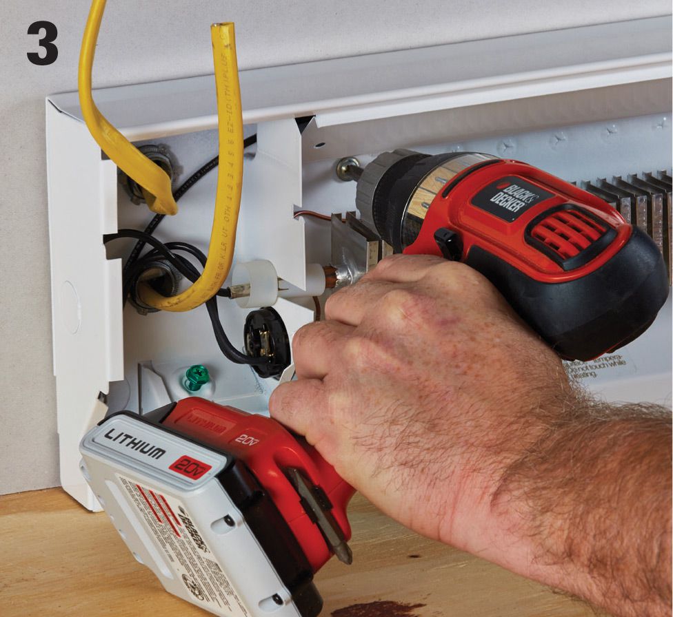
Anchor the heater against wall about 1" off floor by driving flathead screws through the back of the housing and into studs. Strip away cable sheathing so at least 1/2" of sheathing extends into the heater. Strip 3/4" of insulation from each wire using a combination tool.
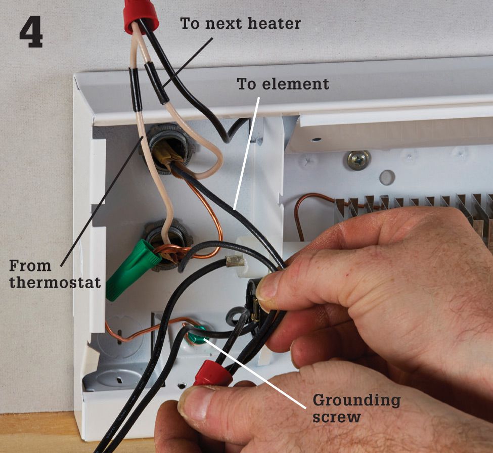
Make connections to the heating element if the power wires are coming from a thermostat or another heater controlled by a thermostat. See the next page for other wiring schemes. Connect the white circuit wires to one of the wire leads on the heater. Tag white wires with black tape to indicate they are hot. Connect the black circuit wires to the other wire lead. Connect a grounding pigtail to the green grounding screw in the box, and then join all grounding wires with a wire connector. Reattach the cover.
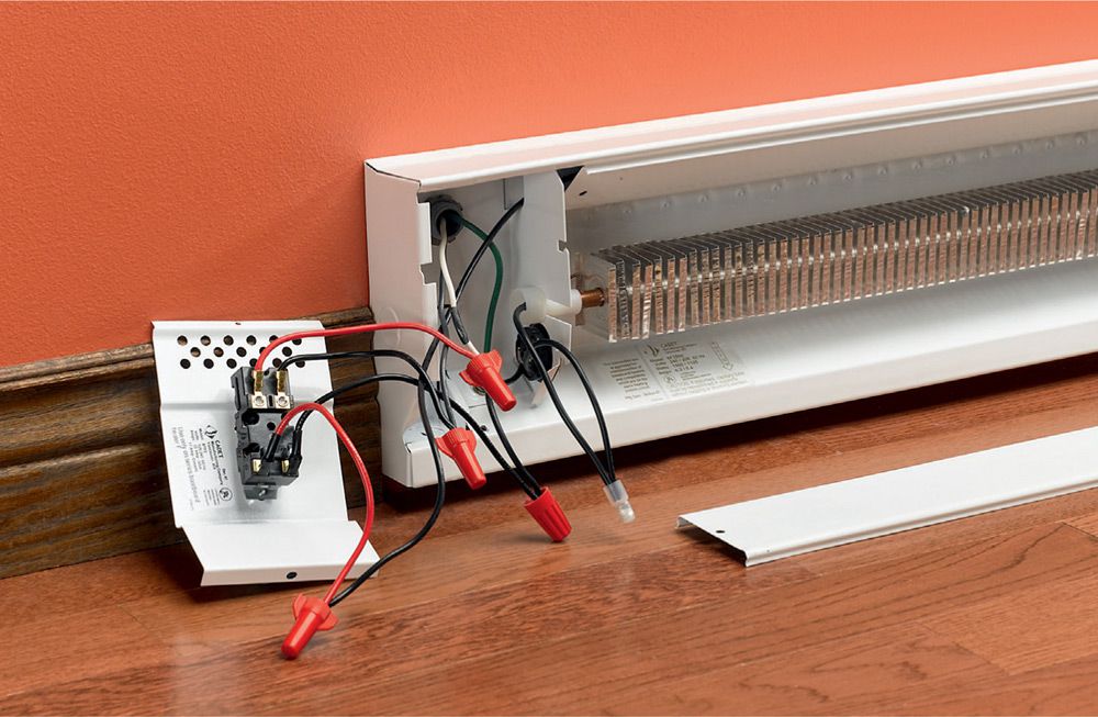
One heater with end-cap thermostat. Run both power leads (black plus tagged neutral) into the connection box at either end of the heater. If installing a single-pole thermostat, connect one power lead to one thermostat wire and connect the other thermostat wire, to one of the heater leads. Connect the other hot LINE wire to the other heater lead. If you are installing a double-pole thermostat, make connections with both legs of the power supply.
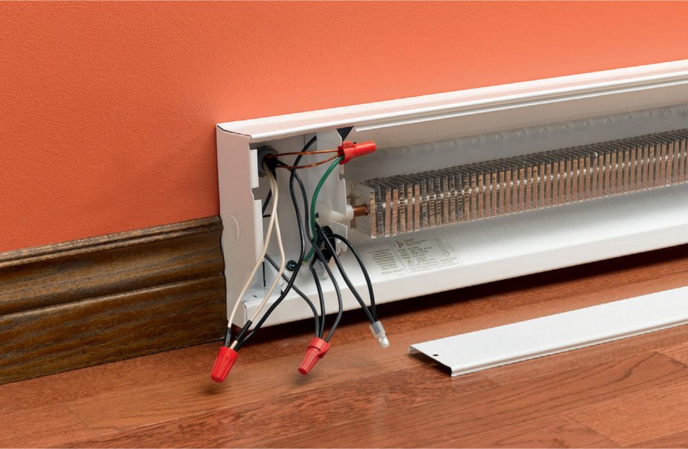
Multiple heaters. At the first heater, join both hot wires from the thermostat to the wires leading to the second heater in line. Be sure to tag all white neutrals hot. Twist copper ground wires together and pigtail them to the grounding screw in the baseboard heater junction box. This parallel wiring configuration ensures that power flow will not be interrupted to the downstream heaters if an upstream heater fails.
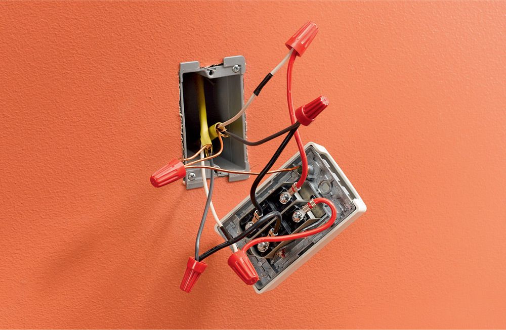
Wall-mounted thermostat. If installing a wall-mounted thermostat, the power leads should enter the thermostat first and then be wired to the individual heaters singly or in series. Hookups at the heater are made as shown in step 4. Be sure to tag the white neutral as hot in the thermostat box as well as in the heater box.
![]() Wall Heaters
Wall Heaters
Installing a wall heater is an easy way to provide supplemental heat to a converted attic or basement without expanding an existing HVAC system.
Wall heaters are easy to install during a remodel (most have a separate can assembly that you attach to the framing before the drywall is installed). They can also be retrofitted.
Most models available at home centers use 120-volt current (shown below), but 240-volt models are also available.
Tools & Materials ![]()
Drywall saw
Drill
Fish tape
Combination tool
Screwdrivers
12/2 NM cable
Wire connectors
Wall heater
Thermostat (optional)
Wallboard saw
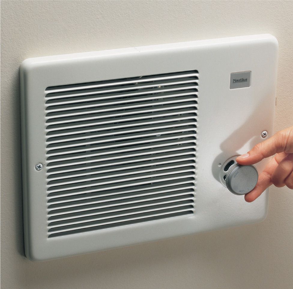
Wall heaters are an easy-to-install way to provide supplemental heat. Some models have built-in thermostats, while others can be controlled by a remote thermostat.
![]() How to Install a Wall Heater in a Finished Wall
How to Install a Wall Heater in a Finished Wall
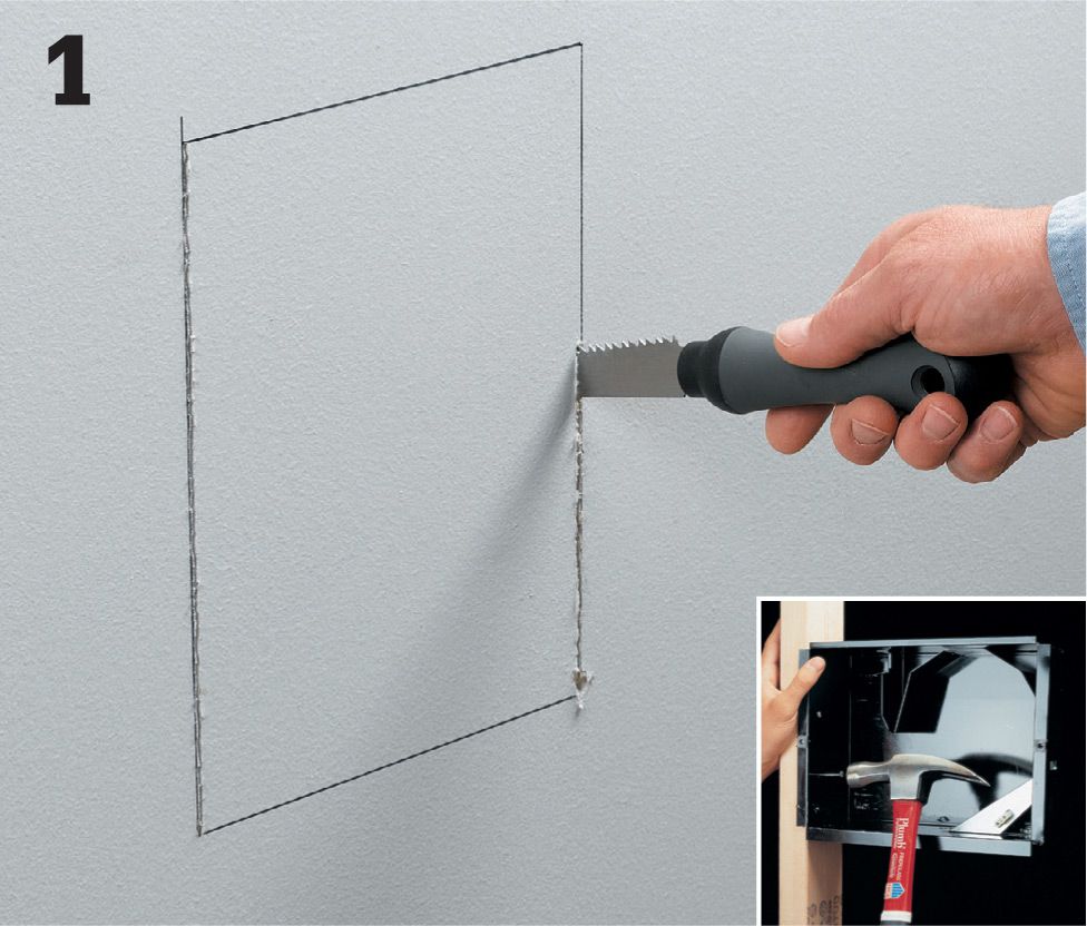
Make an opening in the wall for the heater. Use a stud finder to locate a stud in the area where you want to install the heater. Mark the opening for the heater according to the manufacturer’s guidelines so that one side of the heater sits flush with a stud. Pay attention to clearance requirements. Cut the opening with a wallboard saw. If the wall is open, install the heater can before hanging drywall (inset).
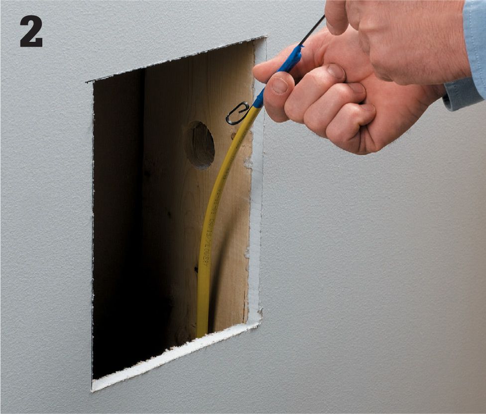
Turn power off, and test for power. Pull 12/2 NM cable from the main panel to the wall opening. If the heater is controlled by a separate thermostat, pull cable to the thermostat, and then run another cable from the thermostat to the heater location.
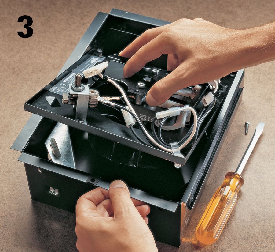
Disconnect and remove the motor unit from the heater can. Remove a knockout from the can, and route the cable into the can.
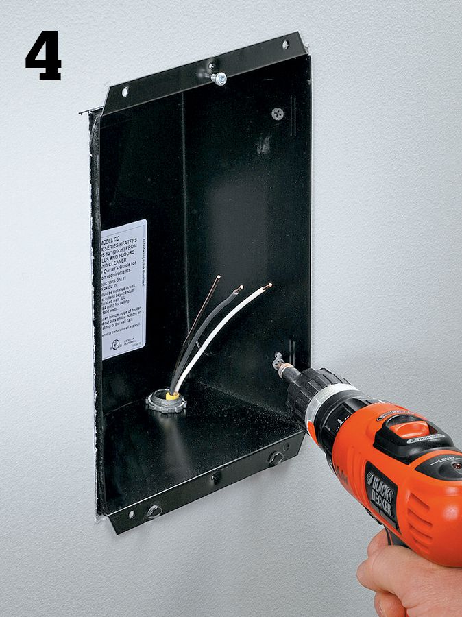
Install the can in the opening. Secure the cable with a clamp, leaving 8" to 12" of cable exposed. Attach the can to the framing as directed by the manufacturer.
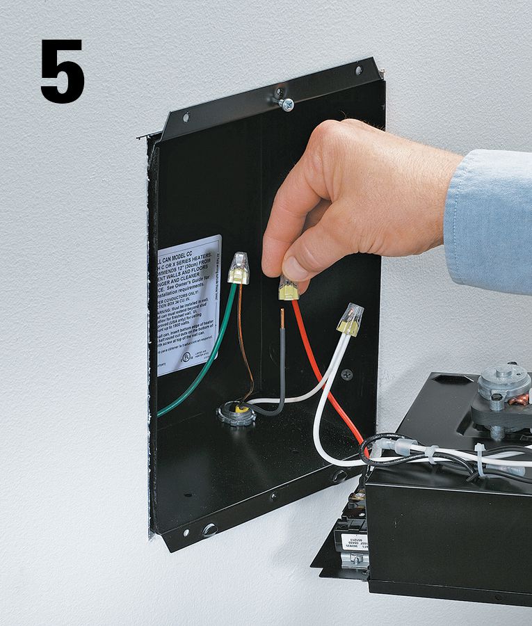
Wire the heater. Connect the black circuit wire to one of the black heater leads. Connect the white circuit wire to the other lead. Connect the grounds.
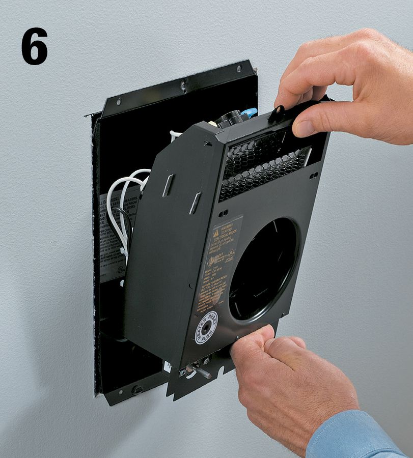
Secure the heater unit in the can as directed by the manufacturer. Reconnect the motor if necessary. Attach the grill and thermostat knob as directed. Connect the new circuit breaker at the main panel.
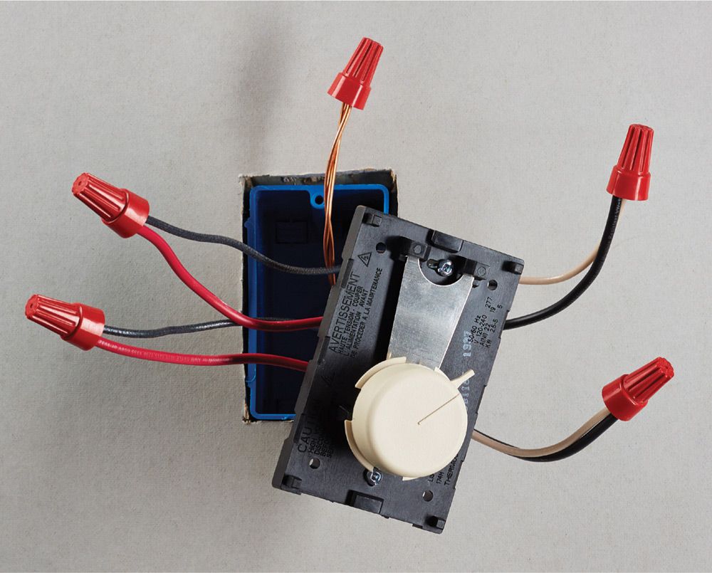
Variation: Connect a thermostat to control a wall heater. Some wall heaters do not use built-in thermostats. Install a thermostat in the heater circuit before the wall heater. Connect the black and the white wires coming from the main panel to the red leads on the thermostat. Connect the wires going to the heater to the black leads on the thermostat. Connect the grounds.
![]() Underfloor Radiant Heat Systems
Underfloor Radiant Heat Systems
Floor-warming systems require very little energy to run and are designed to heat ceramic tile floors only; they generally are not used as sole heat sources for rooms.
A typical floor-warming system consists of one or more thin mats containing electric resistance wires that heat up when energized, like an electric blanket. The mats are installed beneath the tile and are hardwired to a 120-volt GFCI circuit. A thermostat controls the temperature, and a timer turns the system off automatically.
The system shown in this project includes two plastic mesh mats, each with its own power lead that is wired directly to the thermostat. Radiant mats may be installed over a plywood subfloor, but if you plan to install floor tile you should put down a base of cementboard first, and then install the mats on top of the cementboard.
A crucial part of installing this system is to use a multimeter to perform several resistance checks to make sure the heating wires have not been damaged during shipping or installation.
Electrical service required for a floor-warming system is based on size. A smaller system may connect to an existing circuit, but a larger one will need a dedicated circuit; follow the manufacturer’s requirements. These systems should be on a GFCI-protected circuit.
To order a floor-warming system, contact the manufacturer or dealer (see Resources, page 331). In most cases, you can send them plans and they’ll custom-fit a system for your project area.
Tools & Materials ![]()
Vacuum cleaner
Multimeter
Tape measure
Scissors
Router/rotary tool
Marker
Electric wire fault indicator (optional)
Hot glue gun
Radiant floor mats
12/2 NM cable
Trowel or rubber float
Conduit
Thinset mortar
Thermostat with sensor
Junction box(es)
Tile or stone floorcovering
Drill
Double-sided carpet tape
Cable clamps
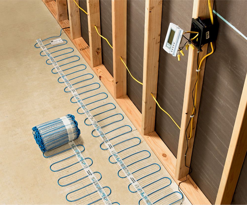
A radiant floor-warming system employs electric heating mats that are covered with floor tile to create a floor that’s cozy underfoot.
Installation Tips ![]()
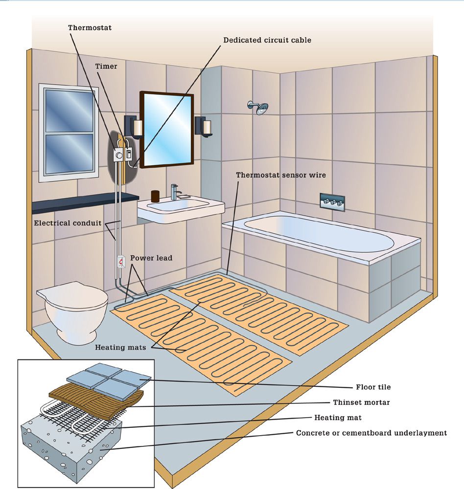
A floor-warming system requires a dedicated GFCI circuit to power and control its heating mats, thermostat, and timer.
✵ Each radiant mat must have a direct connection to the power lead from the thermostat, with the connection made in a junction box in the wall cavity. Do not install mats in series.
✵ Do not install radiant floor mats under shower areas.
✵ Do not overlap mats or let them touch.
✵ Do not cut heating wire or damage heating wire insulation.
✵ The distance between wires in adjoining mats should equal the distance between wire loops measured center to center.
![]() Installing a Radiant Floor-Warming System
Installing a Radiant Floor-Warming System
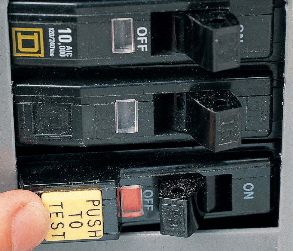
Floor-warming systems must be installed on a circuit with adequate amperage and a GFCI breaker. Smaller systems may tie into an existing circuit, but larger ones need a dedicated circuit. Follow local building and electrical codes that apply to your project.
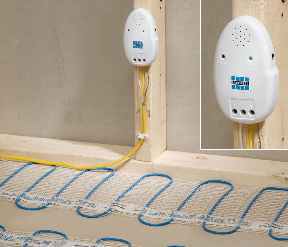
An electric wire fault indicator monitors each floor mat for continuity during the installation process. If there is a break in continuity (for example, if a wire is cut) an alarm sounds. If you choose not to use an installation tool to monitor the mat, test for continuity frequently using a multimeter.
![]() How To Install a Radiant Floor-Warming System
How To Install a Radiant Floor-Warming System
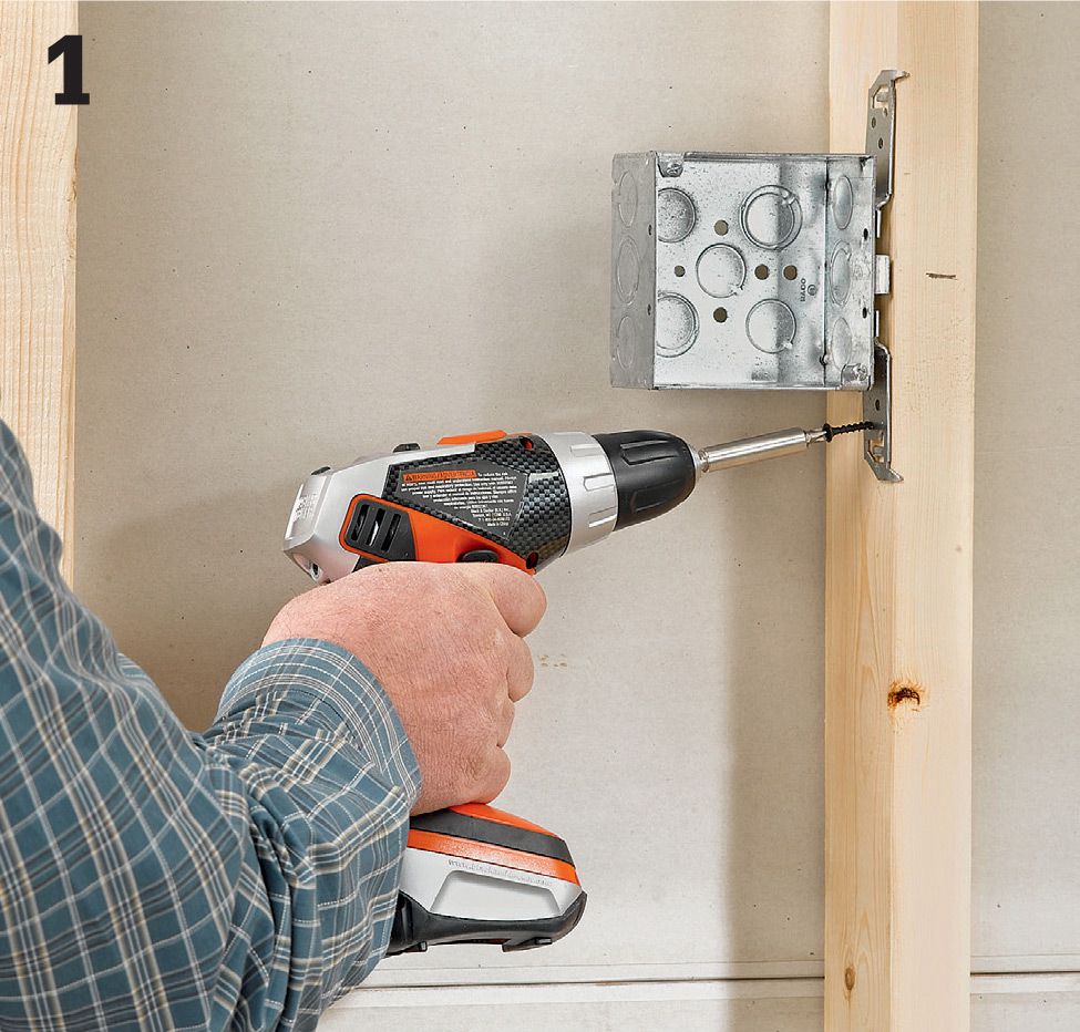
Install electrical boxes to house the thermostat and timer. In most cases, the box should be located 60" above floor level. Use a 4"-deep × 4"-wide double-gang box for the thermostat/timer control if your kit has an integral model. If your timer and thermostat are separate, install a separate single box for the timer.
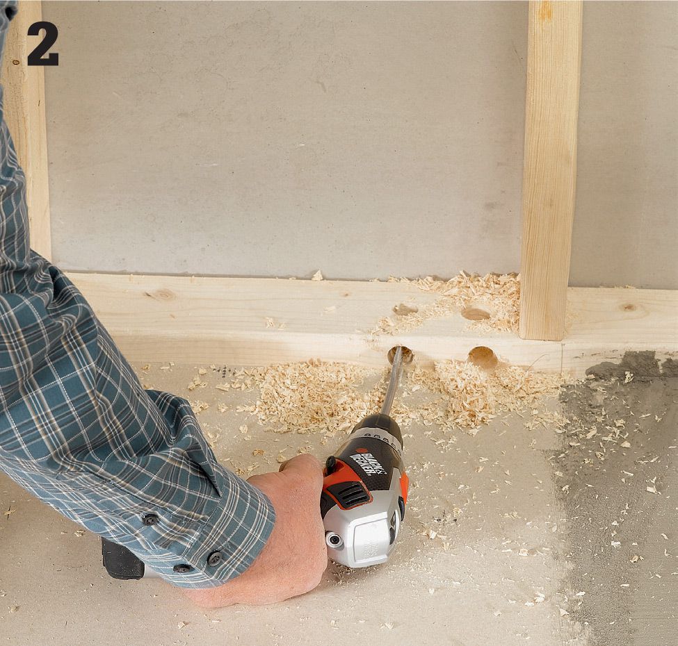
Drill access holes in the sole plate for the power leads that are preattached to the mats (they should be over 10 ft. long). The leads should be connected to a supply wire from the thermostat in a junction box located in a wall near the floor and below the thermostat box. The access hole for each mat should be located directly beneath the knockout for that cable in the thermostat box. Drill through the sill plate vertically and horizontally so the holes meet in an L-shape.
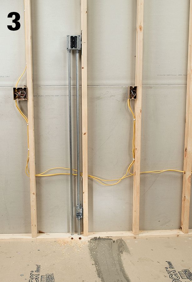
Run conduit from the electrical boxes to the sill plate. The line for the supply cable should be 3/4" conduit. If you are installing multiple mats, the supply conduit should feed into a junction box about 6" above the sill plate and then continue into the 3/4" hole you drilled for the supply leads. The sensor wire needs only 1/2" conduit that runs straight from the thermostat box via the thermostat. The mats should be powered by a dedicated 20-amp GFCI circuit of 12/2 NM cable run from your main service panel to the electrical box (this is for 120-volt mats—check your instruction manual for specific circuit recommendations).
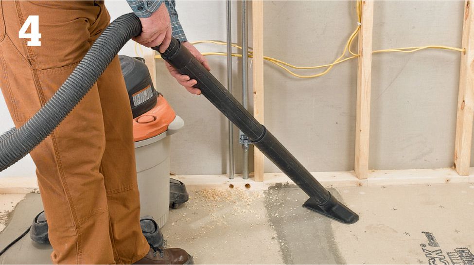
Clean the floor surface thoroughly to get rid of any debris that could potentially damage the wire mats. A vacuum cleaner generally does a more effective job than a broom.
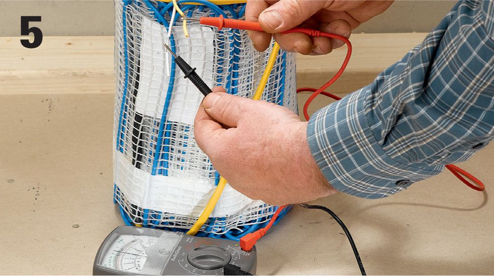
Test for resistance using a multimeter set to measure ohms. This is a test you should make frequently during the installation, along with checking for continuity. If the resistance is off by more than 10% from the theoretical resistance listing (see manufacturer’s chart in installation instructions), contact a technical support operator for the kit manufacturer. For example, the theoretical resistance for the 1 × 50 ft. mat seen here is 19, so the ohms reading should be between 17 and 21.
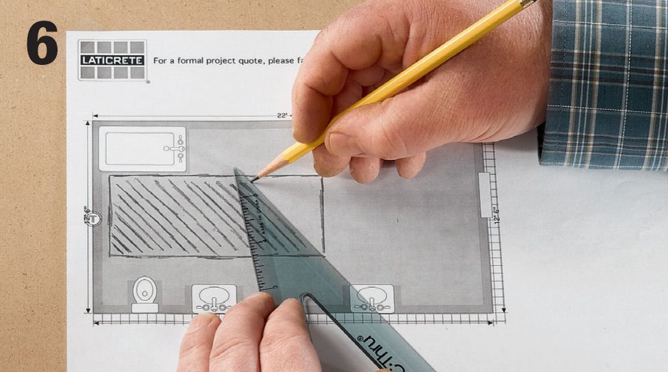
Finalize your mat layout plan. Most radiant floor warming mat manufacturers will provide a layout plan for you at the time of purchase, or they will give you access to an online design tool so you can come up with your own plan. This is an important step to the success of your project, and the assistance is free.
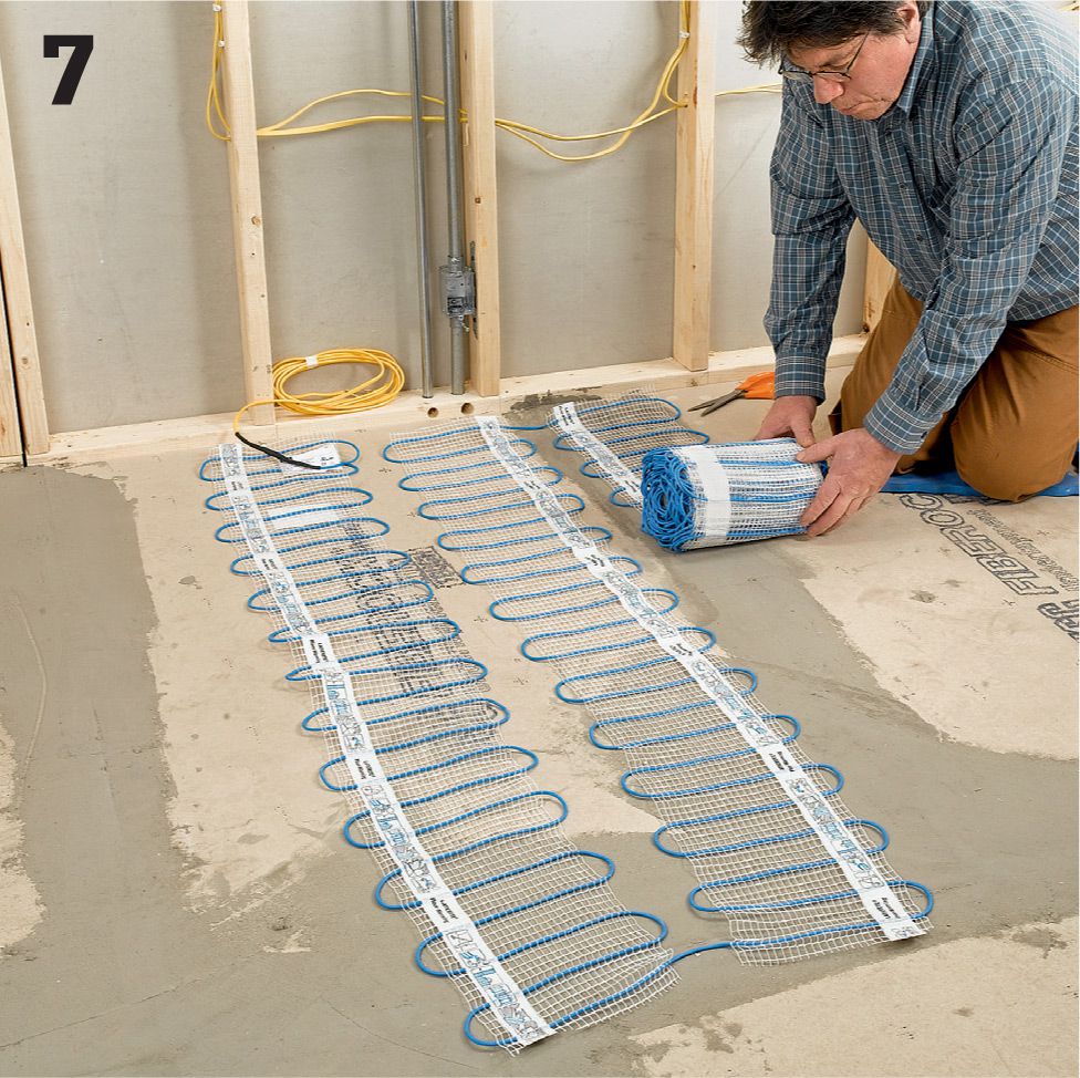
Unroll the radiant mat or mats and allow them to settle. Arrange the mat or mats according to the plan you created. It’s okay to cut the plastic mesh so you can make curves or switchbacks, but do not cut the heating wire under any circumstances, even to shorten it.
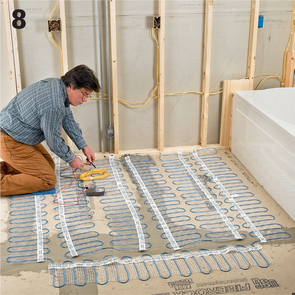
Finalize the mat layout, and then test the resistance again using a multimeter. Also check for continuity in several different spots. If there is a problem with any of the mats, you should identify it and correct it before proceeding with the mortar installation.
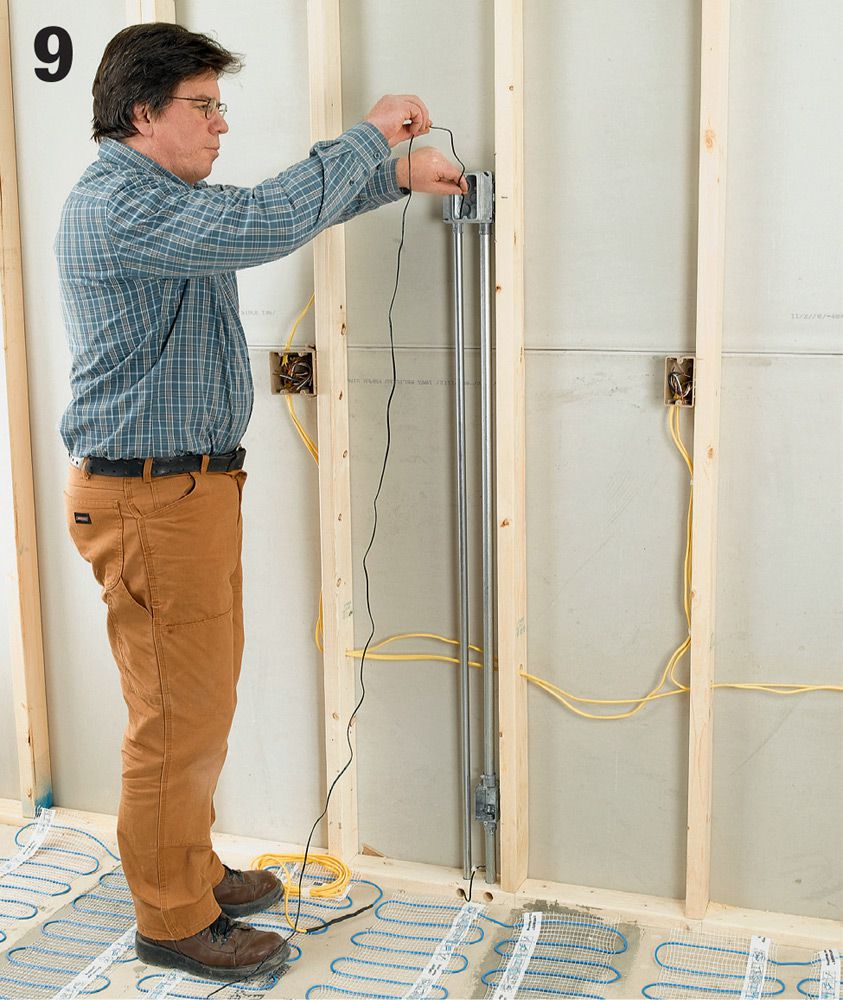
Run the thermostat sensor wire from the electrical box down the 1/2" conduit raceway and out the access hole in the sill plate. Select the best location for the thermostat sensor, and mark the location onto the flooring. Also mark the locations of the wires that connect to and lead from the sensor.
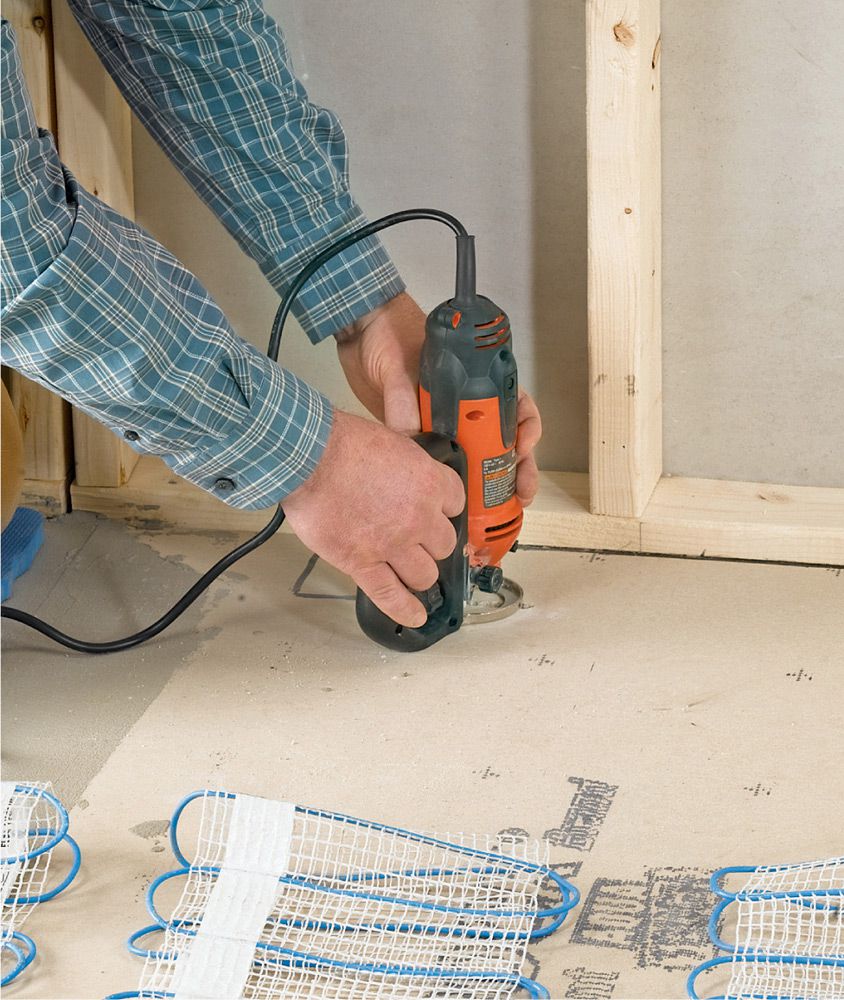
Variation: If your local codes require it, roll the mats out of the way, and cut a channel for the sensor and the sensor wires into the floor or floor underlayment. For most floor materials, a spiral cutting tool does a quick and neat job of this task. Remove any debris.
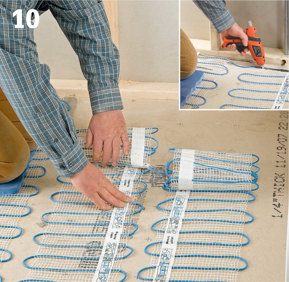
Bond the mats to the floor. If the mats in your system have adhesive strips, peel off the adhesive backing and roll out the mats in the correct position, pressing them against the floor to set the adhesive. If your mats have no adhesive, bind them with strips of double-sided carpet tape. The thermostat sensor and the power supply leads should be attached with hot glue (inset photo) and run up into their respective holes in the sill plate if you have not done this already. Test all mats for resistance and continuity.
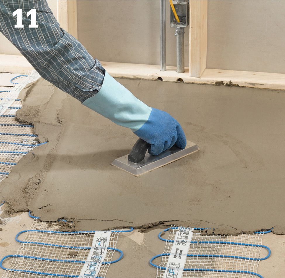
Cover the floor installation areas with a layer of thinset mortar that is thick enough to fully encapsulate all the wires and mats (usually around 1/4" in thickness). Check the wires for continuity and resistance regularly, and stop working immediately if there is a drop in resistance or a failure of continuity. Allow the mortar to dry overnight.
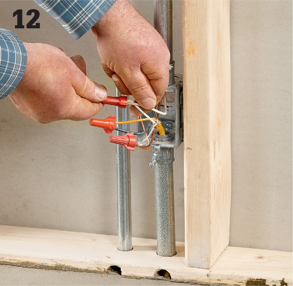
Connect the power supply leads from the mat or mats to the NM cable coming from the thermostat inside the junction box near the sill. Power must be turned off. The power leads should be cut so about 8" of wire feeds into the box. Be sure to use cable clamps to protect the wires.
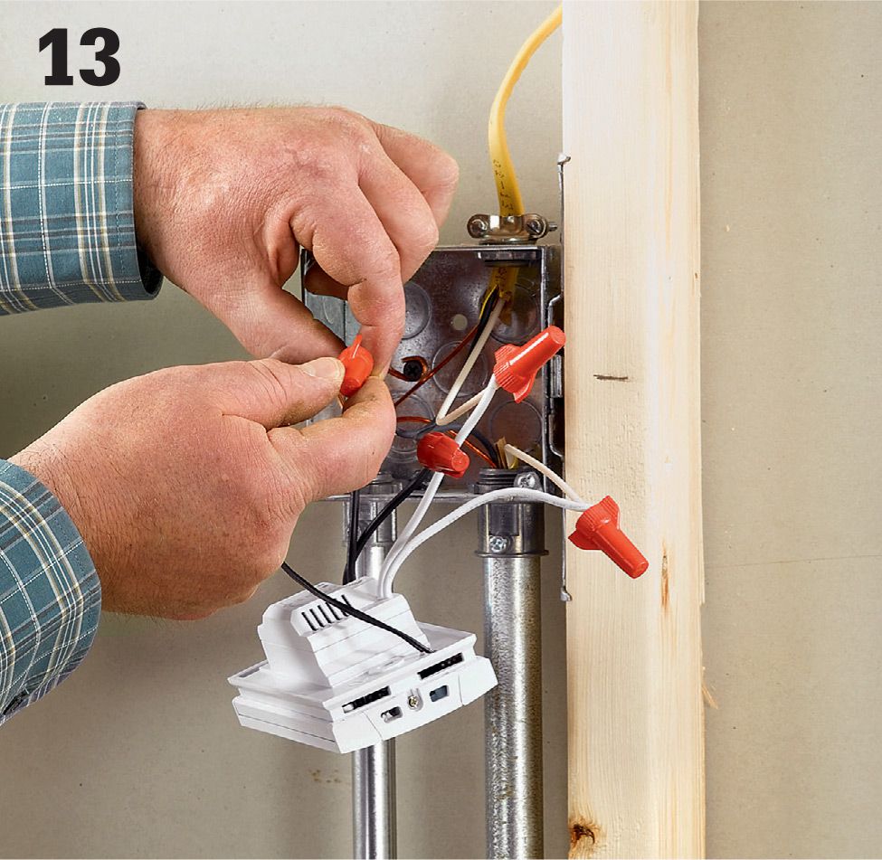
Connect the sensor wire and the power supply lead (from the junction box) to the thermostat/timer according to the manufacturer’s directions. Attach the device to the electrical box, restore power, and test the system to make sure it works. Once you are convinced that it is operating properly, install floor tiles and repair the wall surfaces.
![]() Ceiling Fans
Ceiling Fans
Ceiling fans are installed and wired like ceiling fixtures. They always require heavy-duty bracing and electrical boxes rated for ceiling fans.
Most standard ceiling fans work with a wall switch functioning as master power for the unit. Pull chains attached to the unit control the fan and lights. In these installations, it’s fairly simple to replace an existing ceiling fixture with a fan and light.
If you will be installing a new circuit for the fan, use three-wire cable so both the light and the motor can be controlled by wall switches (see circuit maps 30 and 31, page 165).
Because ceiling fans generally weigh more than ceiling lights and the motion of the blade creates more stress, it is very important that the ceiling box is securely mounted and is rated for ceiling fans. Ceiling boxes rated for ceiling fans are marked with the phrase “For ceiling fan support.” If your existing ceiling box is not fan-rated, replace it with one that is. And be sure to inspect the manner in which the box is mounted to make sure it is strong enough (see page 246).
Installation varies from fan to fan, so be sure to follow the manufacturer’s instructions.
Tools & Materials ![]()
Screwdriver
Combination tool
Pliers or adjustable wrench
Circuit tester
Hammer
Ceiling fan light kit
2 × 4 lumber or adjustable ceiling fan crossbrace
1 1/2" and 3" coarse- thread screws
Eye protection
Downrod (if needed)
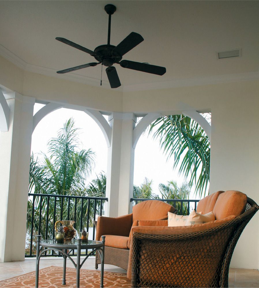
A ceiling fan helps keep living spaces cooler in the summer and warmer in the winter. Replacing an overhead light with a fan/light is an easy project with big payback.
![]() Ceiling Fan Types
Ceiling Fan Types
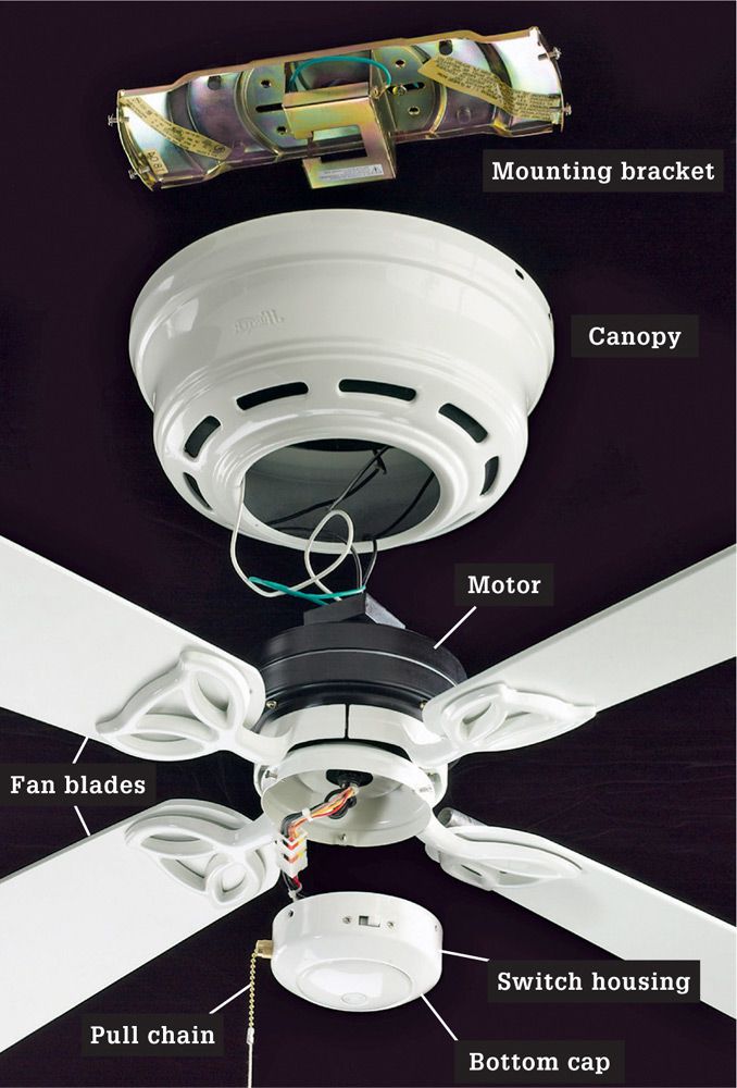
Bracket-mounted ceiling fans are hung directly from a mounting bracket that is attached to the ceiling box. A canopy conceals the motor and the connections.
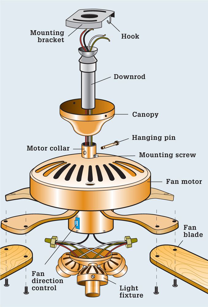
Downrod mounted ceiling fans are supported by a metal rod that’s hung from the ceiling mounting bracket. The length of the rod determines the height of the fan. Downrod fans are used in rooms with ceilings 8 ft. high or higher. You may need to buy a longer downrod if you have a very high ceiling.
Fans That Heat ![]()
The first generation of ceiling fans did one job: they spun and moved air. As the technology advanced, light kits were added to replace the light source that is lost when a fan-only appliance is installed. Now, some ceiling fans are manufactured with electric heating elements that can produce up to 5,000 BTUs of heat, comparable to a small space heater. Located in the fan canopy, the ceramic heat elements direct heat out the vents and force it down to the living level in the room, along with the heated air that naturally rises.
Fan-mounted heaters are relatively light duty, so they generally do not require a dedicated circuit. In most cases, you can supply power to the heater/fan with any 15-amp room light circuit that has extra capacity.
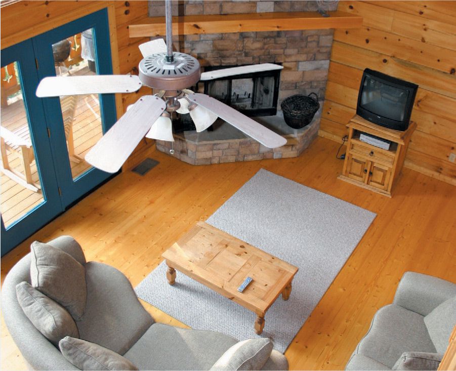
![]() Supporting Ceiling Boxes
Supporting Ceiling Boxes
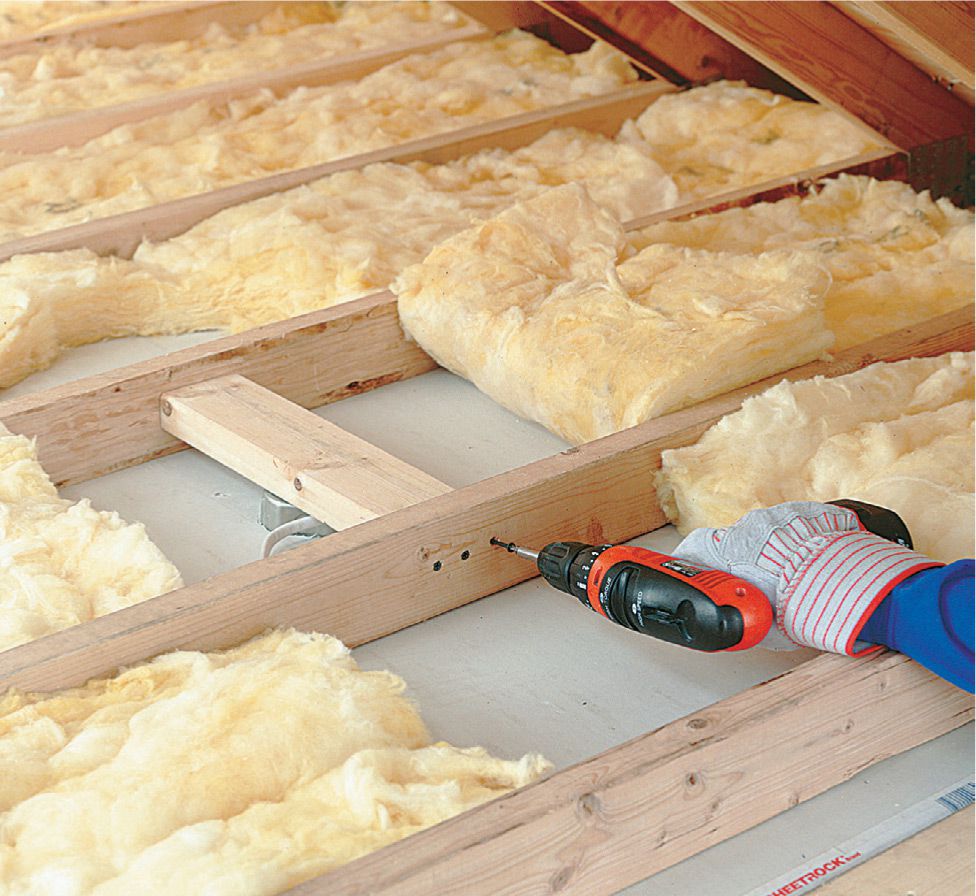
Add a wood brace above the ceiling box if you have access from above (as in an attic). Cut a 24" brace to fit and nail it between the ceiling joists. Drive a couple of deck screws through the ceiling box and into the brace. If the box is not fan-rated, replace it with one that is.
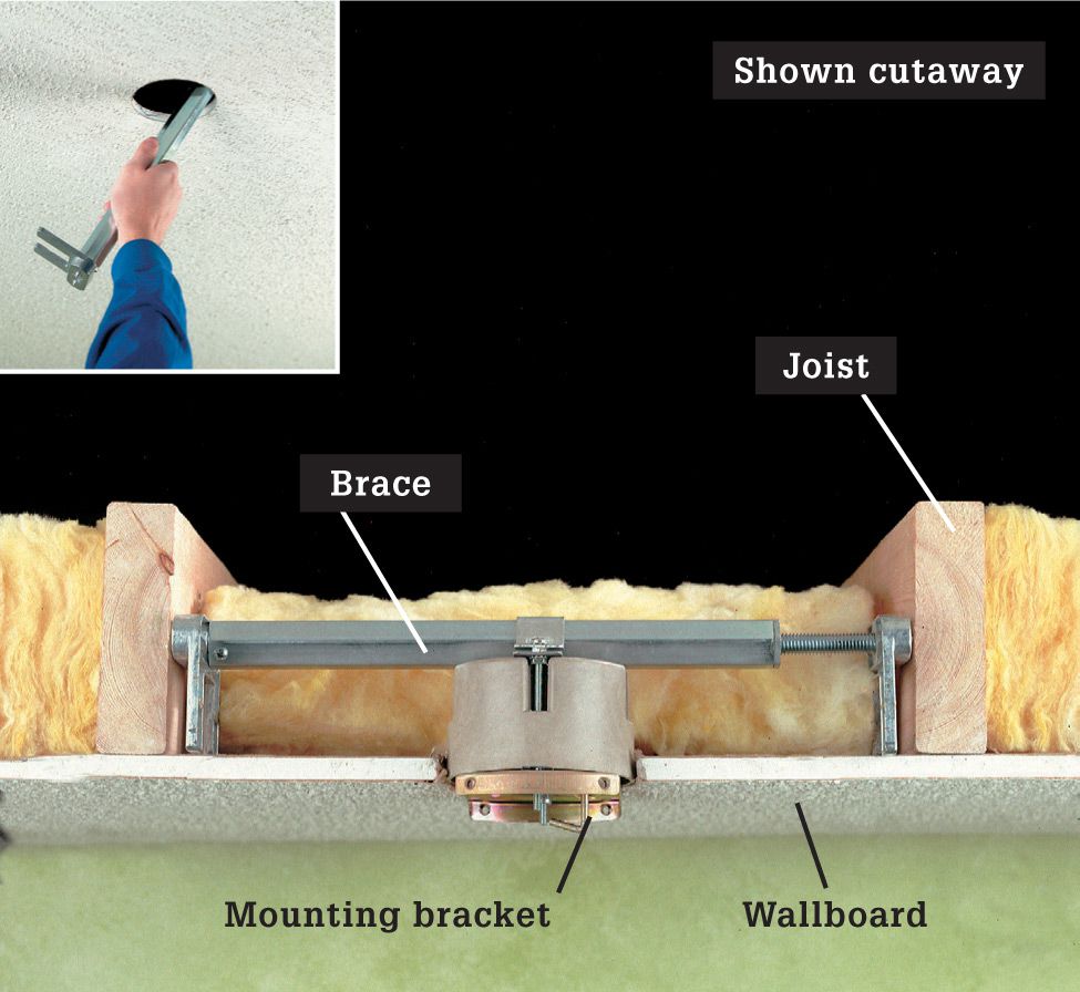
Install an adjustable fan brace if the ceiling is closed and you don’t want to remove the wallcoverings. Remove the old light and the electrical box, and then insert the fan brace into the box opening (inset photo). Twist the brace housing to cause it to telescope outward. The brace should be centered over the opening and at the right height so the ceiling box is flush with the ceiling surface once it is hung from the brace.
![]() Bracket-Mounted Fans
Bracket-Mounted Fans
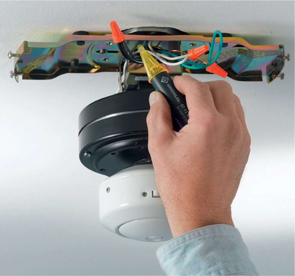
Direct-mount fan units have a motor housing with a mounting tab that fits directly into a slot on the mounting bracket. Fans with this mounting approach are secure and easy to install but difficult to adjust.
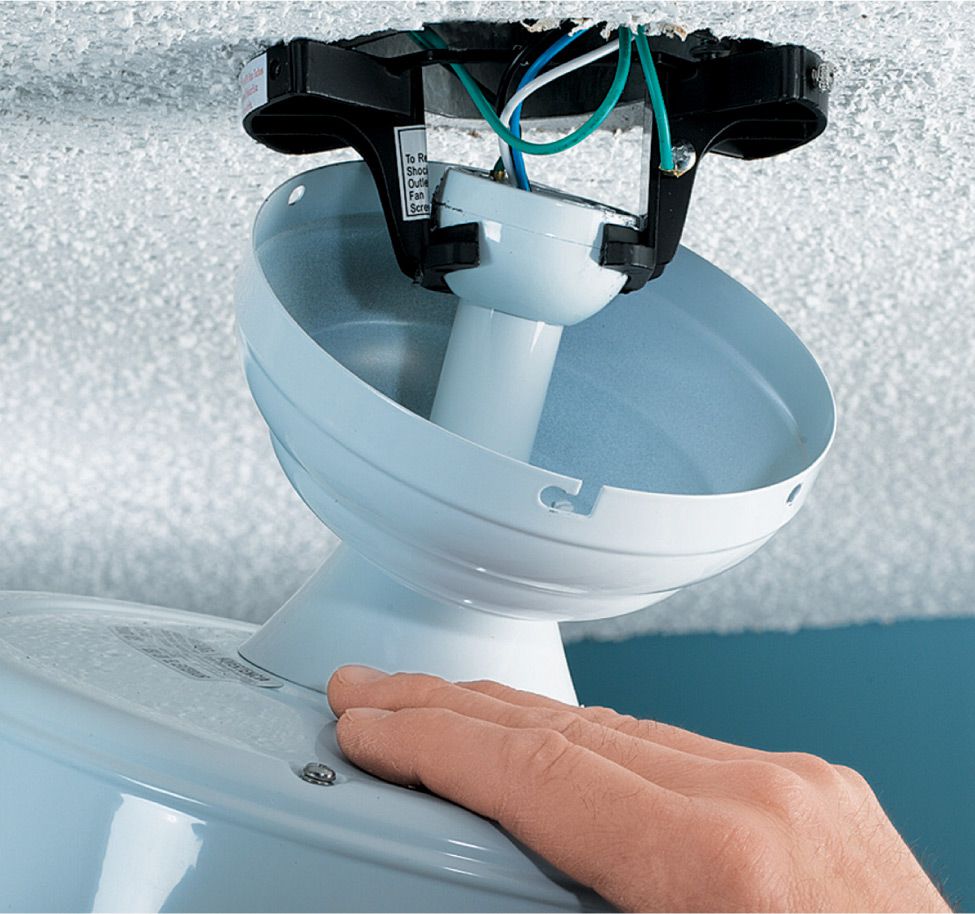
Ball-and-socket fan units have a downrod, but instead of threading into the mounting bracket, the downrod has an attached ball that fits into a hanger “socket” in the mounting bracket. This installation allows the fan to move in the socket and find its own level for quiet operation.
![]() How to Install Downrod Ceiling Fans
How to Install Downrod Ceiling Fans
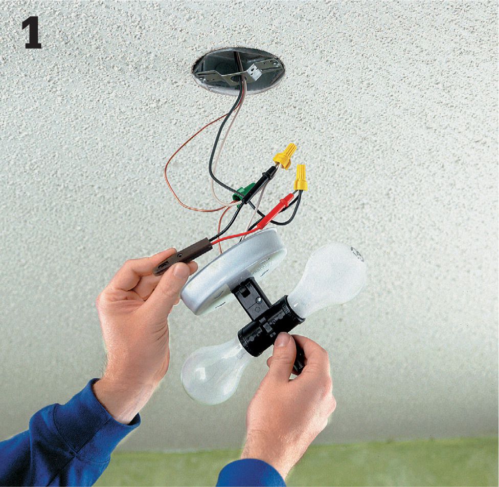
Shut off the power to the circuit at the panel. Unscrew the existing fixture and carefully pull it away from the ceiling. Test for power by inserting the probes of a tester into the wire connectors on the black and the white wires. Disconnect and remove the old fixture.
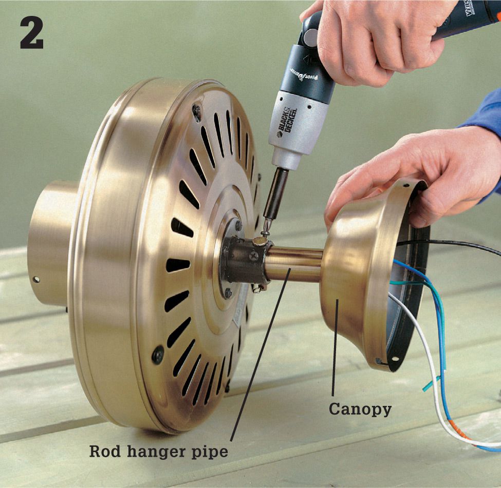
Run the wires from the top of the fan motor through the canopy and then through the rod hanger pipe. Slide the rod hanger pipe through the canopy and attach the pipe to the motor collar using the included hanging pin. Tighten the mounting screws firmly.
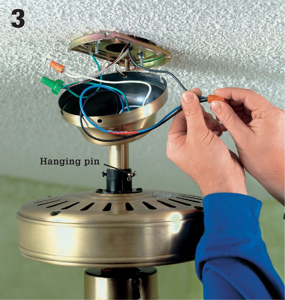
Hang the motor assembly by the hook on the mounting bracket. Connect the wires according to manufacturer’s directions, using wire connectors to join the fixture wires to the circuit wires in the box. Gather the wires together and tuck them inside the fan canopy. Lift the canopy and attach it to the mounting bracket.
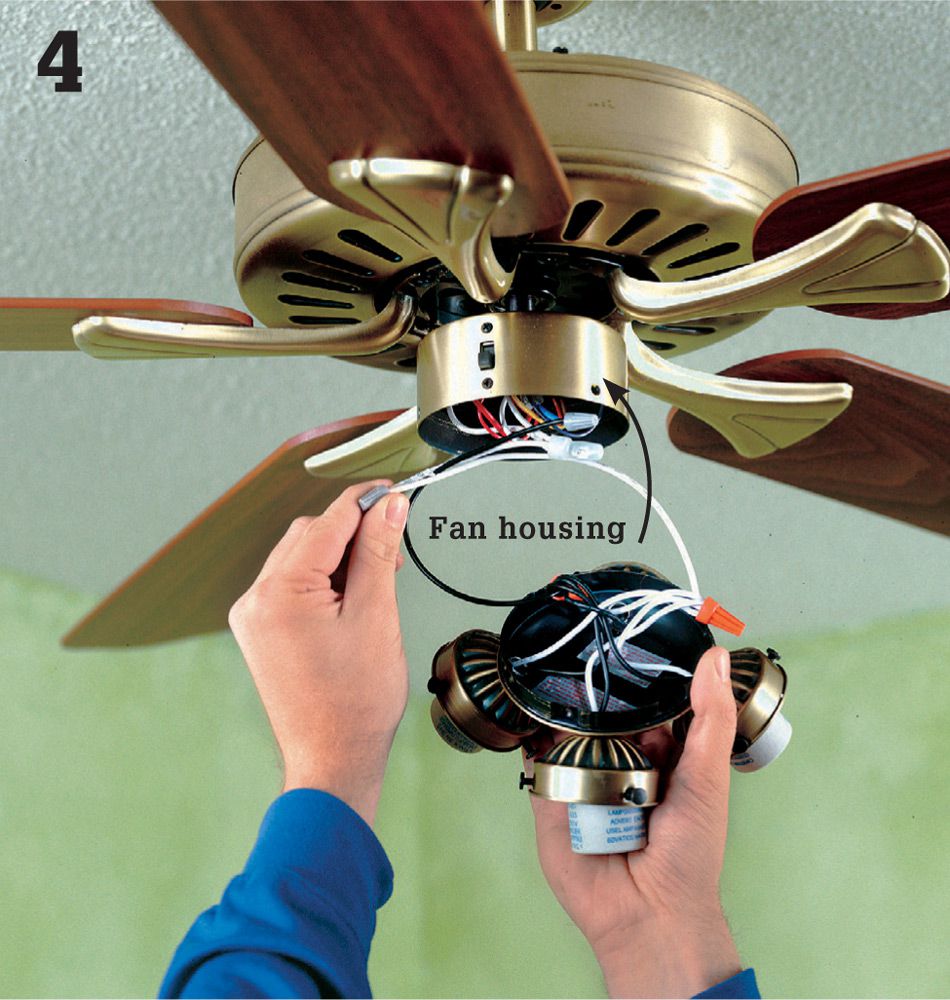
Attach the fan blades with the included hardware. Connect the wiring for the fan’s light fixture according to the manufacturer’s directions. Tuck all wires into the switch housing, and attach the fixture. Install light bulbs. Restore power, and test the fan.
![]() Remote-Control Ceiling Fan Retrofit
Remote-Control Ceiling Fan Retrofit
Ceiling fan remote control switches offer an easy way of controlling both the lighting and fan function of your ceiling fan. They are commonly used when there are only a hot and neutral at the fan location or where the ability to switch two different functions is not present in the wiring. The remote can save you the need to install another switch and/or the need to pull another wire to your ceiling fan. Many different remotes on the market can be used with different manufacturer ceiling fans, so you are not limited to the brand of fan you are using.
Tools & Materials ![]()
Ceiling fan remote kit
Wire connectors
Screwdrivers
Pliers
Needle nose pliers
Wire strippers
Circuit tester
Eye protection
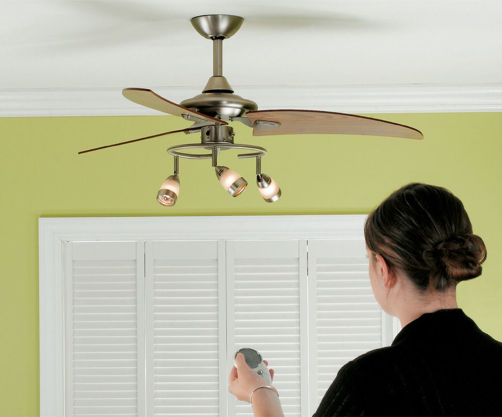
A retrofit remote control kit lets you take the hassle (and the pull chains) out of operating just about any ceiling fan and light.
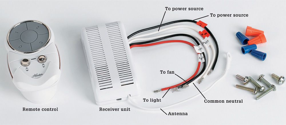
Parts of an aftermarket remote control kit for a ceiling fan usually include the remote control unit (some come with a cradle) and the receiver unit. Your unit may come with color-coded wire connectors and mounting hardware as well.
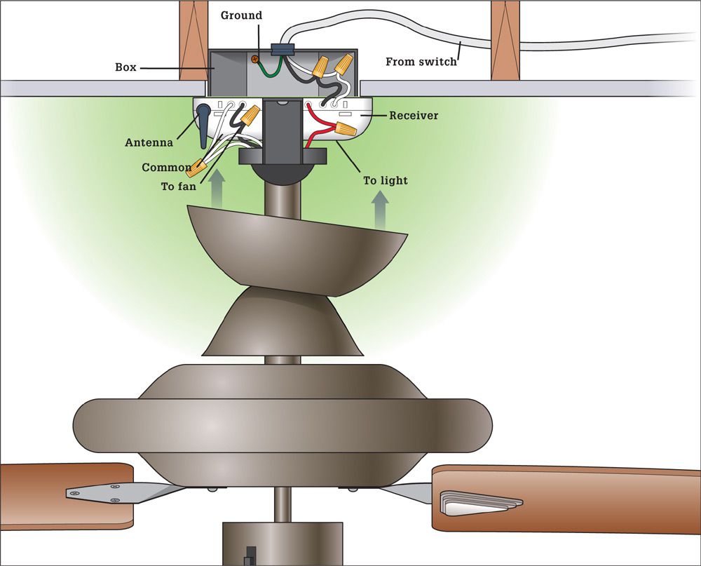
Wiring a remote control fan controller is pretty simple. The black and white feed wires from the power source should be connected to the black and white power input wires coming out the receiver. The red wire from the receiver should be connected to the red wire from the fan light. The white neutral wire from the fan light should be connected to the common white wire coming out of the receiver. The black wire from the fan should be connected to the black fan wire from the receiver. The white neutral wire from the fan should be connected to the common white wire coming out of the receiver. The green ground wire from the power source should be pigtailed to the grounding terminal in the ceiling box.
![]() How to Retrofit a Remote Control to a Ceiling Fan
How to Retrofit a Remote Control to a Ceiling Fan
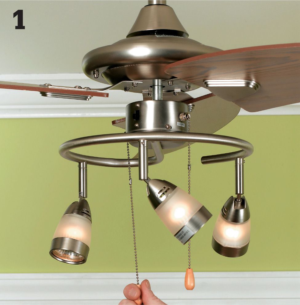
Turn your fan on high speed and turn the lights on. Then, at the main service panel, shut off the power to the circuit that supplies your ceiling fan.
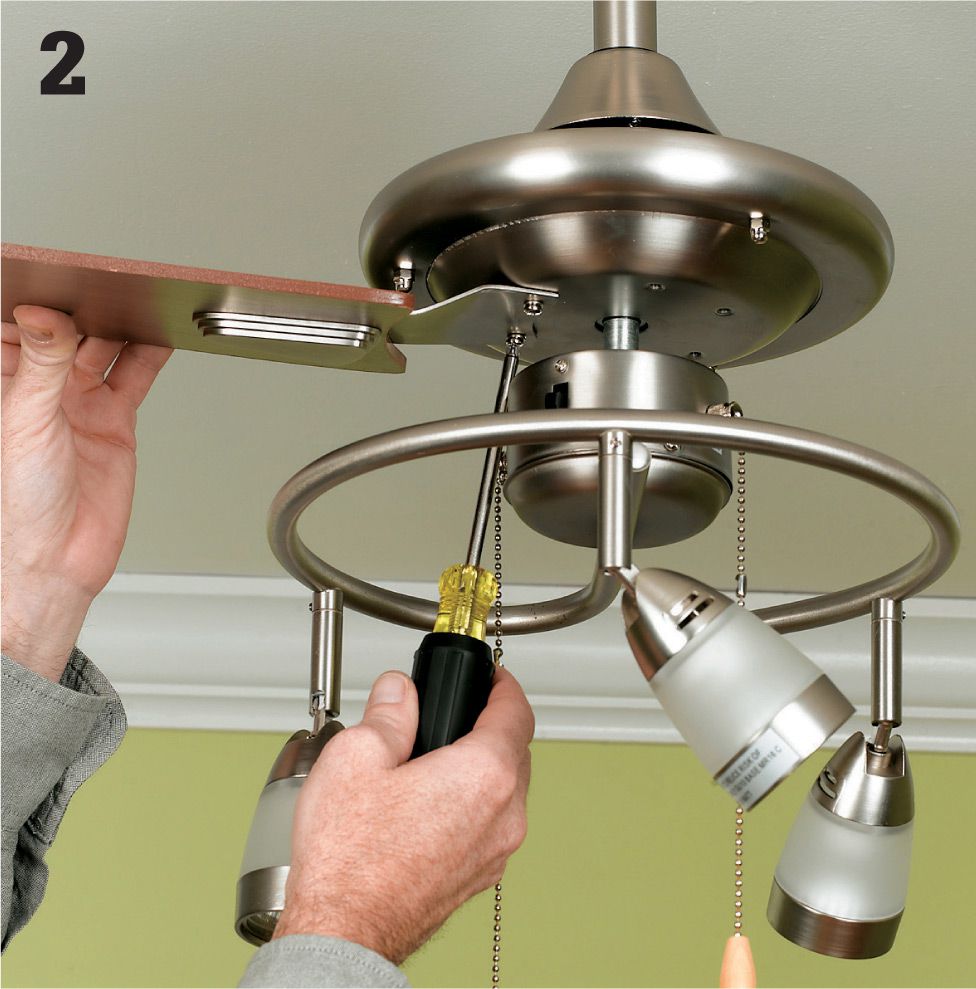
Remove the fan blades, one at a time on opposite sides of one another, so as to not overweight a certain side, which could bend the shaft and create a wobble. There are generally two vertically installed Phillips head #10 screws that hold the blade bracket to the motor housing.
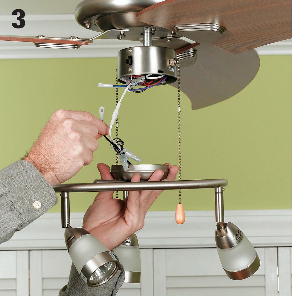
If a light kit was installed on the fan, remove it as well. First, remove the bulbs and any glass diffusers, and then remove the light kit itself. Usually you’ll find three horizontally installed #6 Phillips head screws attached to the pan directly below the motor housing. Unplug the light kit from the fan wires and set aside.
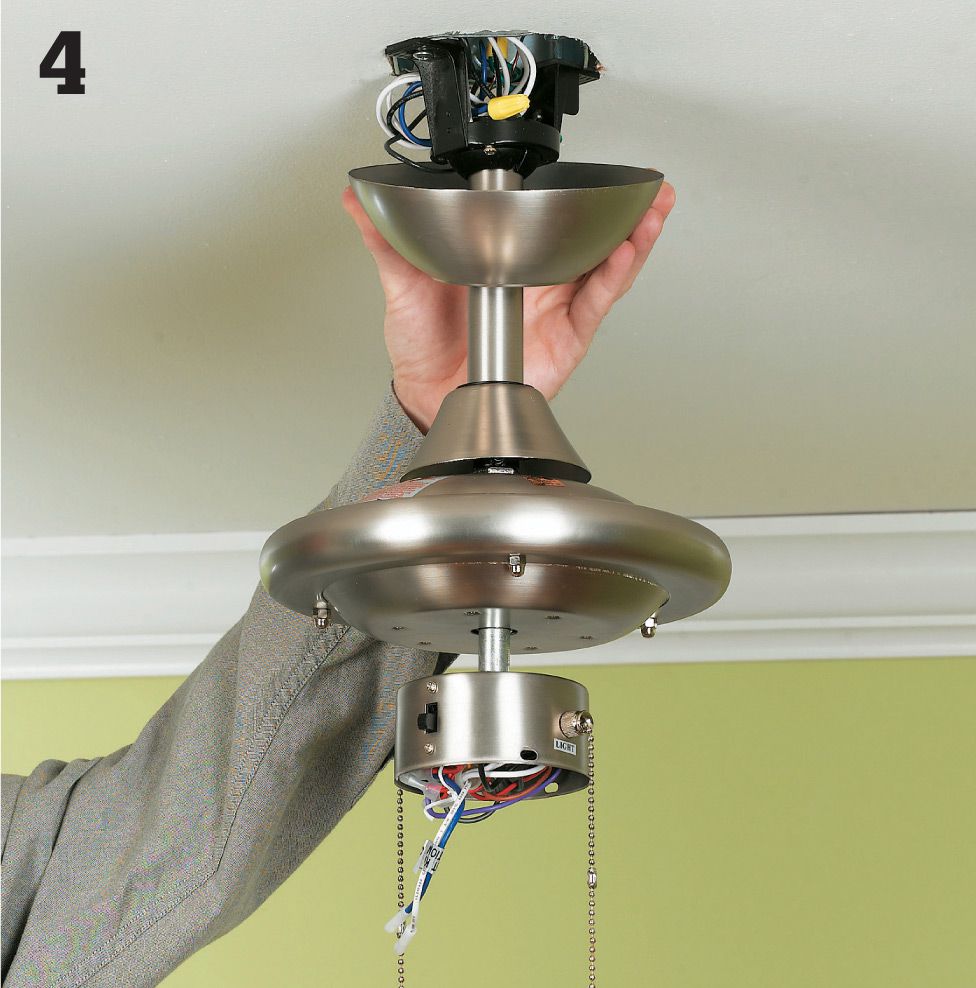
If your fan has a downrod between the motor housing and the ceiling, remove the canopy on the top of the pipe connected to the mounting plate on the ceiling. You should find two to four horizontally installed #6 screws near the base of the canopy. Remove the screws, and slide the canopy down to expose the wiring.
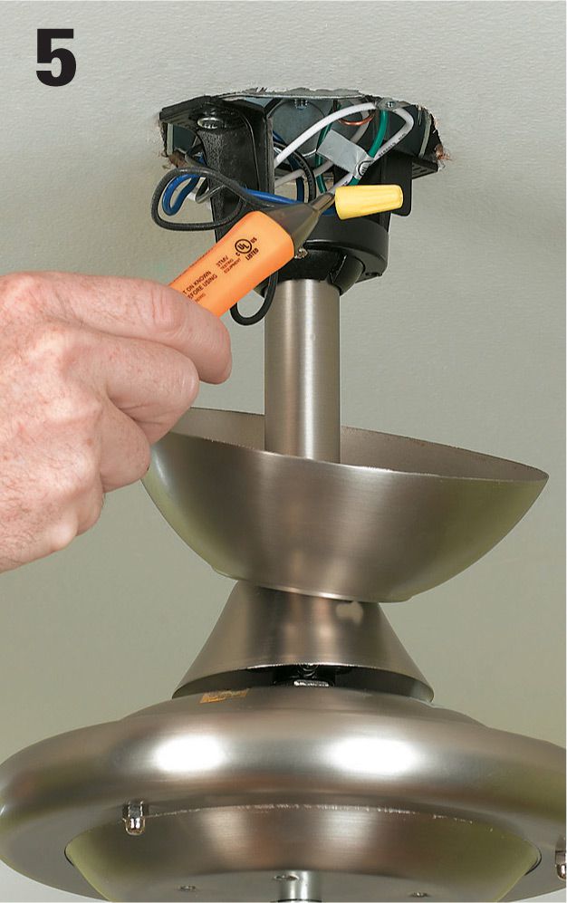
Check all wires with a circuit tester to verify there is no power present.
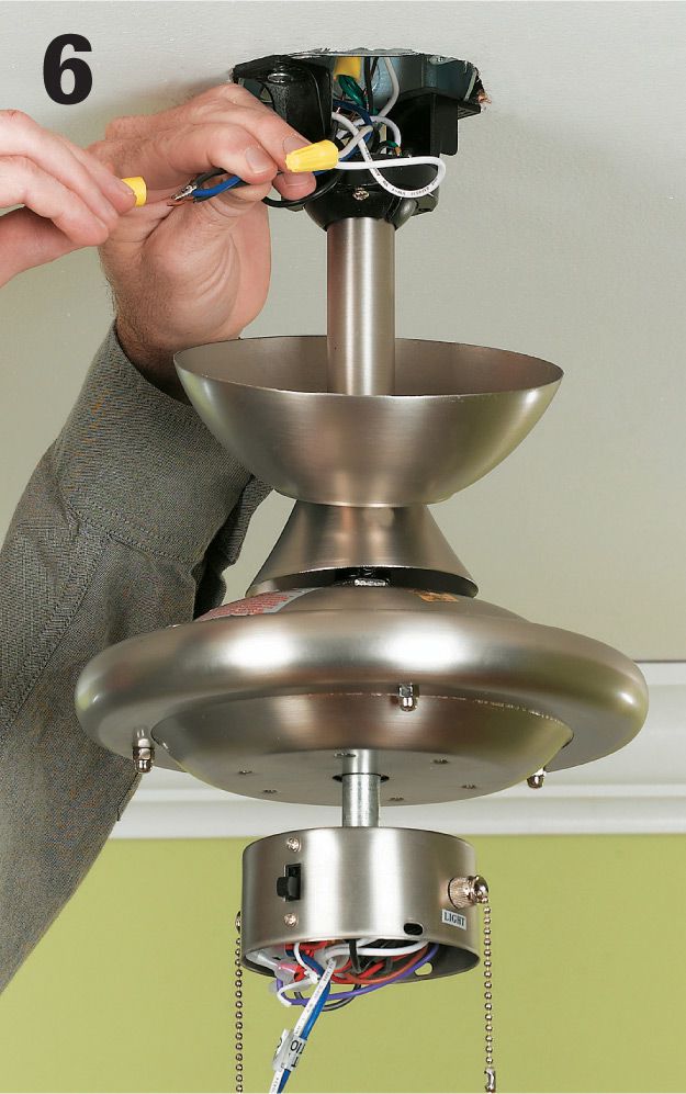
Disconnect the black, red or blue, and white wires from the electrical box wires.
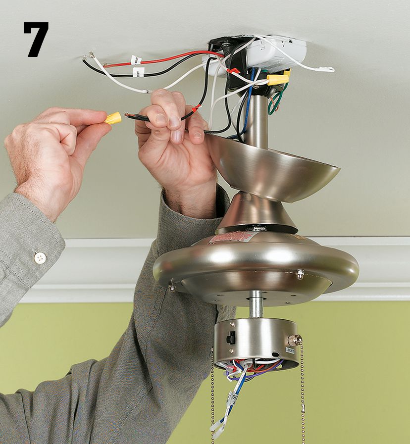
Install the receiving unit of the remote fan kit. Connect the black and white wires from the receiving unit input to the black and the white wires coming from the electrical box in the ceiling. If a red wire was used originally to feed the light portion of the fan, cap this wire with a wire nut and fold it into the box.
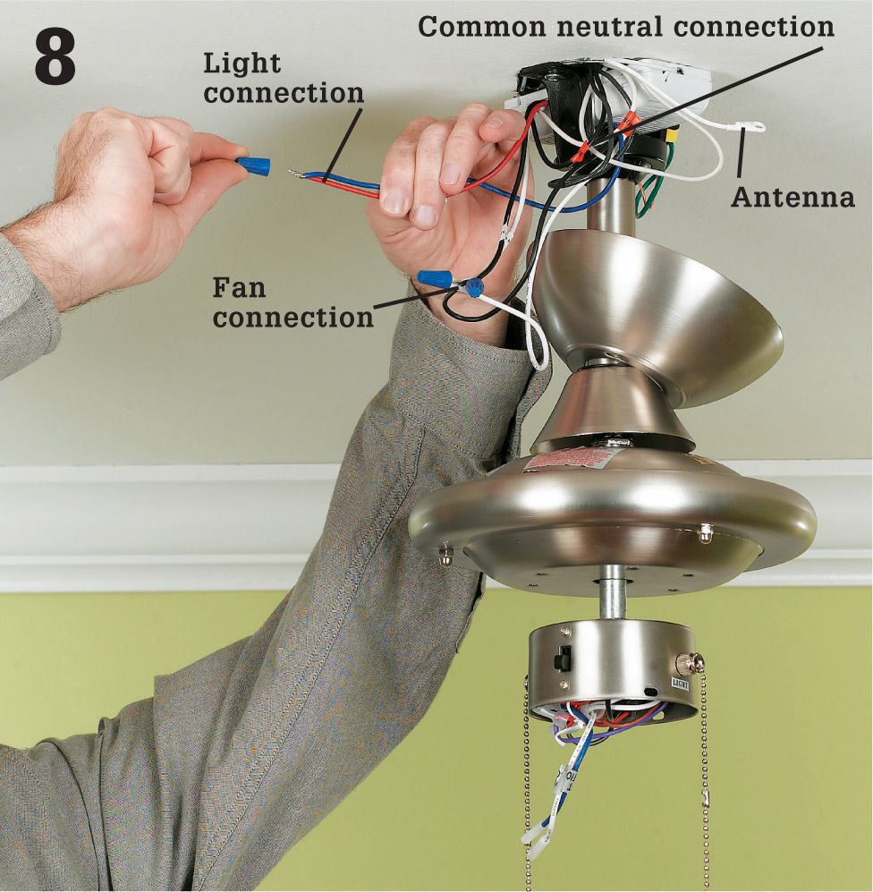
Connect the output of the receiving unit to the fan’s associated wiring: black wire to black wire, white wire to white wire, and blue wire to blue wire (or red to red, or red to blue). If a downrod was used to hang the fan, place the receiving unit above the ball and flange portion of the mounting bracket.
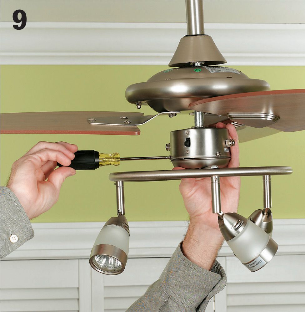
Reinstall the canopy, fan blades, and light kit. Restore power. Install the batteries into the remote control sending unit, and test to make sure the fan is spinning on all three modes: Low, Medium, and High. Test the light switch to verify the light switch works as well. Disconnect and remove the pullchains.
![]() Bathroom Exhaust Fans
Bathroom Exhaust Fans
Most exhaust fans are installed in the center of the bathroom ceiling or over the toilet area. A fan installed over the tub or shower area must be rated for use in wet areas. You can usually wire a fan that just has a light fixture into a main bathroom lighting circuit. Units with built-in heat lamps or blowers require separate circuits.
If the fan you choose doesn’t come with a mounting kit, purchase one separately. A mounting kit should include an exhaust hose (duct), a vent tailpiece, and an exterior terminal.
The most common exhaust options are a roof exhaust and a soffit exhaust. Sometimes the exhaust can be directed out a sidewall. The instructions in this book are for a shingle roof covering. You should have a roofer install the exhaust termination if you have any other roof covering material or if you are not comfortable walking on your roof.
A soffit exhaust involves routing the duct to a soffit (roof overhang) where it is connected to a terminal that directs the exhaust outside. While soffit exhausts are allowed, they are not recommended, because the moisture can be drawn back into the attic through the soffit vents. Check with the exhaust fan manufacturer for instructions about how to run and terminate the exhaust duct.
Tools & Materials ![]()
Drill
Jigsaw
Combination tool
Screwdrivers
Caulk gun
Reciprocating saw
Pry bar
Screws
Double-gang retrofit electrical box
NM cable (14/2, 14/3)
Cable clamp
Hose clamps
Pipe insulation
Roofing cement
Self-sealing roofing nails
Shingles
Wire connectors
Switch and timer
Eye protection
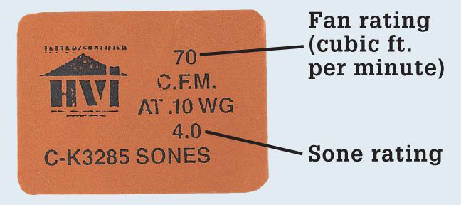
Check the information label attached to each exhaust fan unit. The minimum rating is 50 CFM; larger baths may need up to 100 CFM. The sone rating refers to quietness rated on a scale of 1 to 7; quieter is lower.
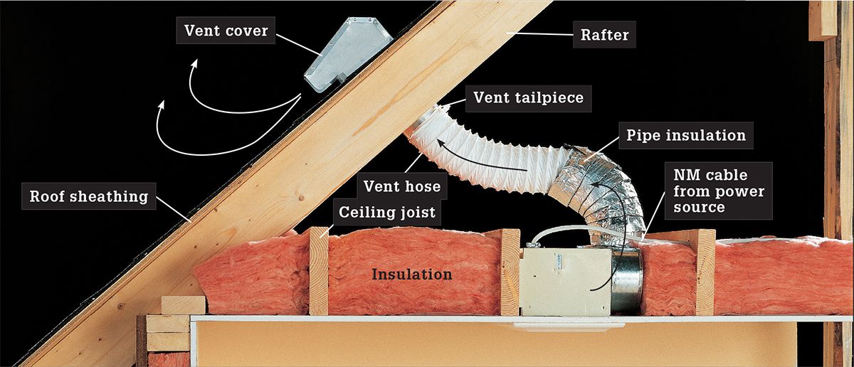
Bathroom exhaust fans must be exhausted to the outdoors, either through the roof or through a wall. Flexible ductwork is allowed for bath exhaust fans (but not for clothes dryers).
![]() How to Install a Bathroom Exhaust Fan
How to Install a Bathroom Exhaust Fan
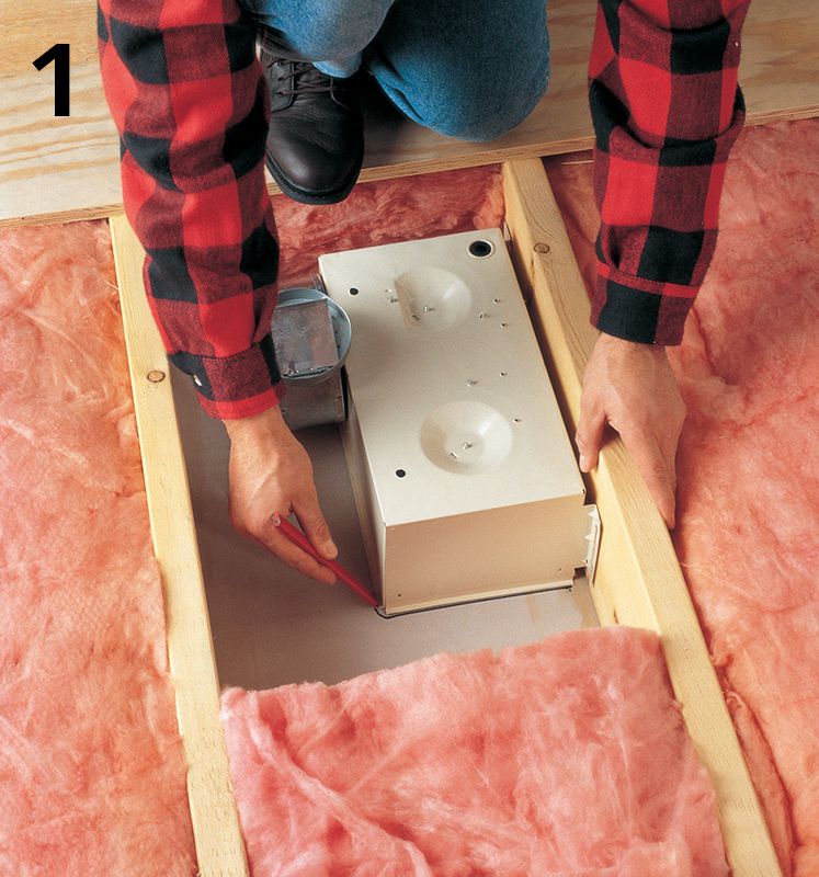
Position the fan unit against a ceiling joist. Outline the fan onto the ceiling surface. Remove the unit, drill pilot holes at the corners of the outline, and cut out the area with a jigsaw or drywall saw.
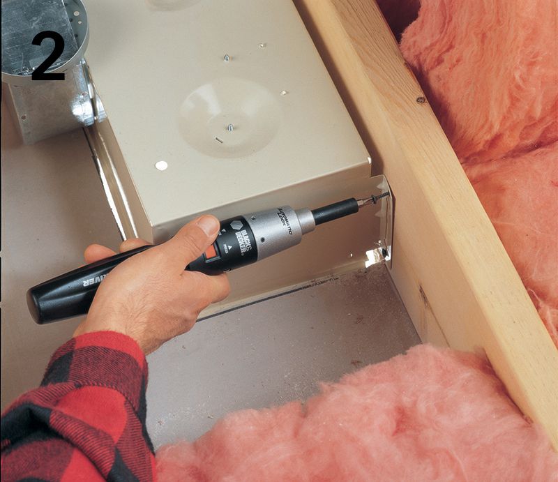
Remove the grille from the fan unit, and then position the unit against the joist with the edge recessed 1/4" from the finished surface of the ceiling (so the grille can be flush mounted). Attach the unit to the joist using drywall screws.
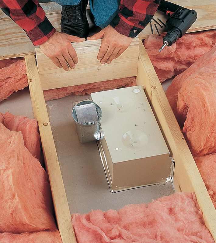
Variation: For fans with heaters or light fixtures, some manufacturers recommend using 2× lumber to build dams between the ceiling joists to keep the insulation at least 6" away from the fan unit.
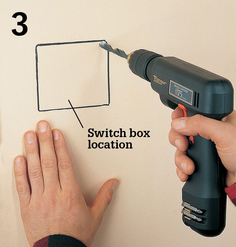
Mark and cut an opening for a double-gang box on the wall next to the latch side of the bathroom door, and then run a 14/3 NM cable from the switch cutout to the fan unit. Run a 14/2 NM cable from the power source to the cutout.
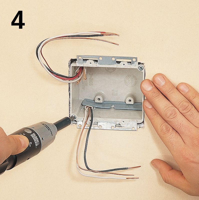
Strip 10" of sheathing from the ends of the cables, and then feed the cables into a double-gang retrofit switch box so at least 1/2" of sheathing extends into the box. Clamp the cables in place. Tighten the mounting screws until the box is secure.
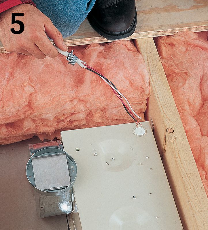
Strip 10" of sheathing from the end of the cable at the unit, and then attach a cable clamp to the cable. Insert the cable into the fan unit. From the inside of the unit, screw a locknut onto the threaded end of the clamp.
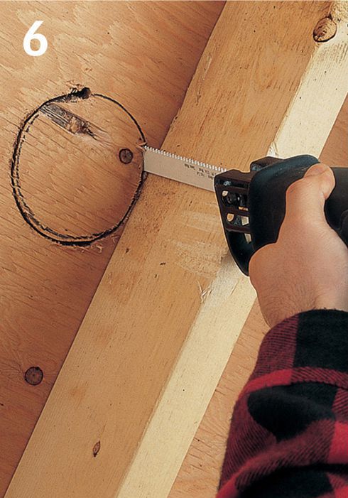
Mark the exit location in the roof next to a rafter for the exhaust duct. Drill a pilot hole, and then saw through the sheathing and roofing material with a reciprocating saw to make the cutout for the exhaust tailpiece.
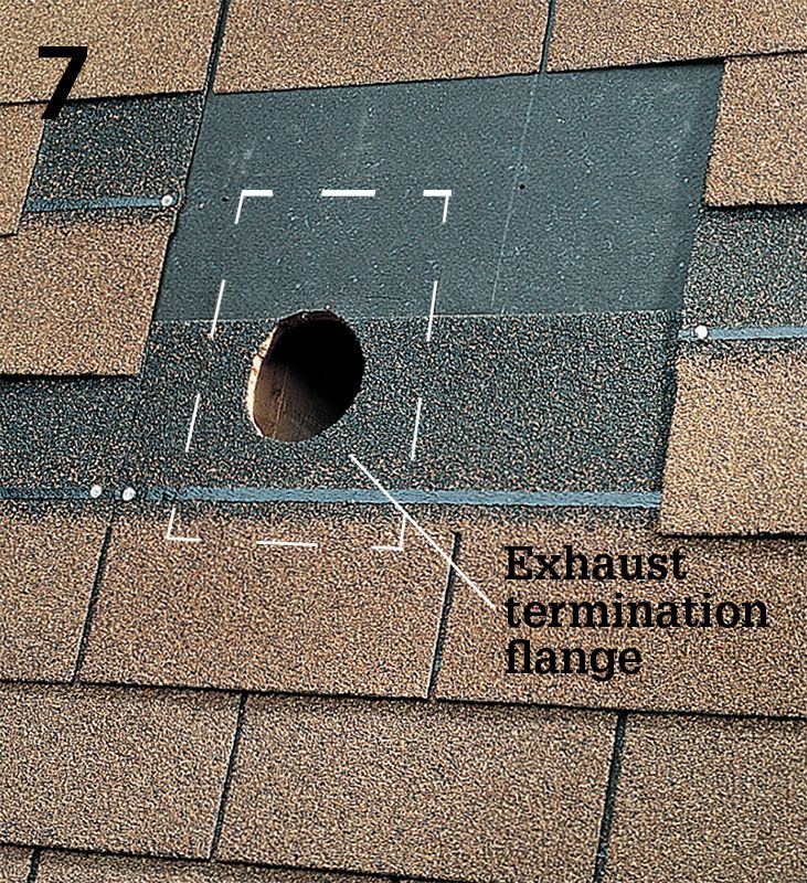
Remove a section of shingles from around the cutout, leaving the roofing paper intact. Remove enough shingles to create an exposed area that is at least the size of the exhaust termination flange.
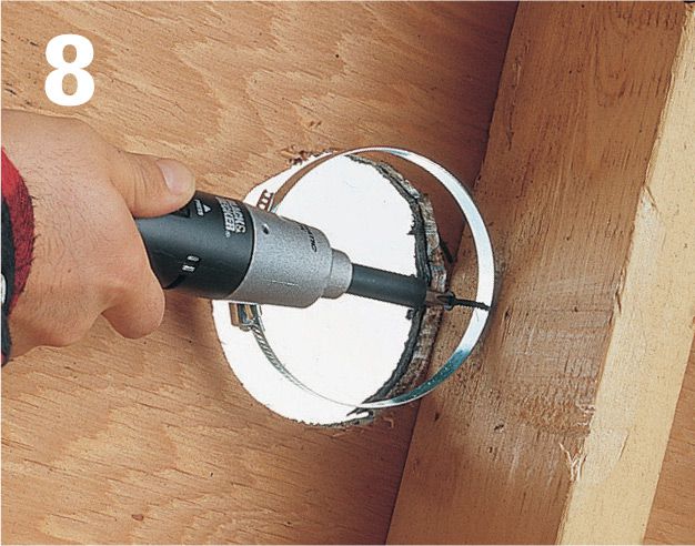
Attach a hose clamp to the rafter next to the roof cutout about 1" below the roof sheathing.
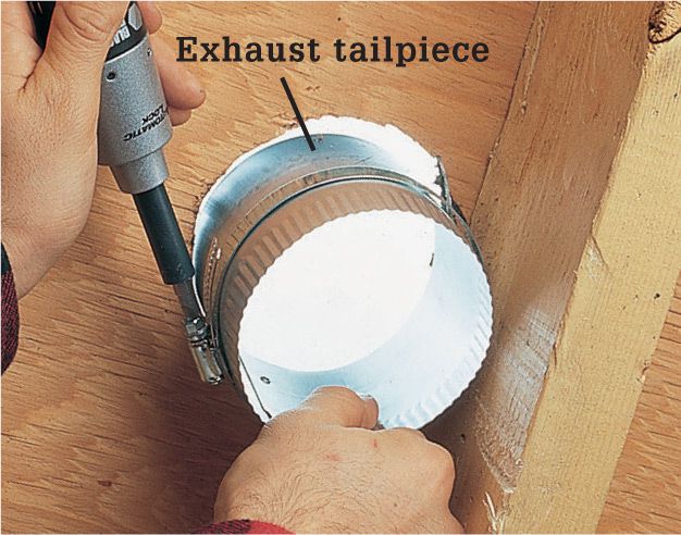
Insert the exhaust tailpiece into the cutout and through the hose clamp, and then tighten the clamp screw.
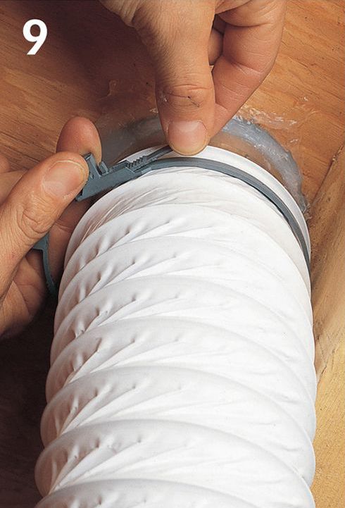
Slide one end of the exhaust duct over the tailpiece, and slide the other end over the outlet on the fan unit. Slip hose clamps or straps around each end of the duct, and tighten the clamps.
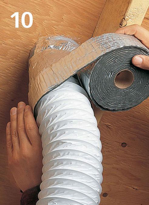
Wrap the exhaust duct with pipe insulation. Insulation prevents moist air inside the hose from condensing and dripping down into the fan motor.

Apply roofing cement to the bottom of the exhaust termination flange, and then slide the termination over the tailpiece. Nail the termination flange in place with self-sealing roofing nails, and then patch in shingles around the cover.
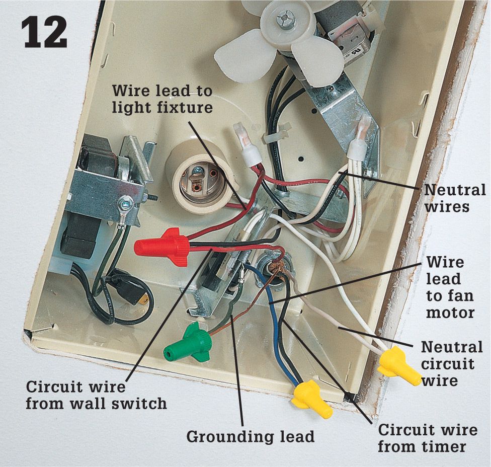
Turn power off, and test for power. Make the following wire connections at the fan unit: the black circuit wire from the timer to the wire lead for the fan motor; the red circuit wire from the single-pole switch (see step 14) to the wire lead for the light fixture in the unit; the white neutral circuit wire to the neutral wire lead; the circuit grounding wire to the grounding lead on the fan unit. Make all connections with wire connectors. Attach the cover plate over the unit when the wiring is completed.
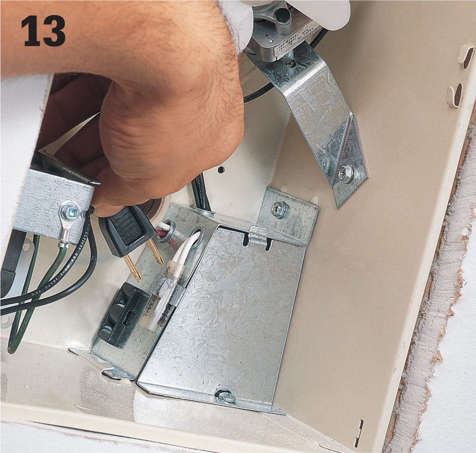
Connect the fan motor plug to the built-in receptacle on the wire connection box, and attach the fan grille to the frame using the mounting clips included with the fan kit. Note: If you removed the wall and ceiling surfaces for the installation, install new surfaces before completing this step.
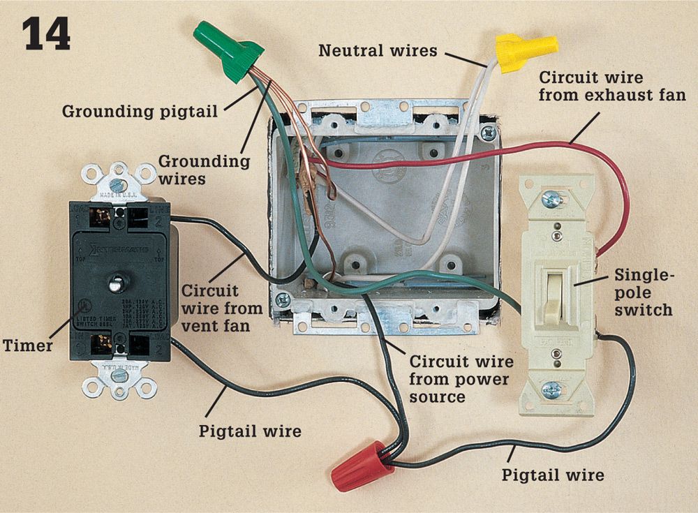
Turn power off, and test for power. At the switch box, add black pigtail wires to one screw terminal on the timer and to one screw terminal on the single-pole switch; add a green grounding pigtail to the groundling screw on the switch. Make the following wire connections: the black circuit wire from the power source to the black pigtail wires; the black circuit wire from the vent fan to the remaining screw on the timer; the red circuit wire from the vent fan to the remaining screw on the switch. Join the white wires with a wire connector. Join the grounding wires with a green wire connector.
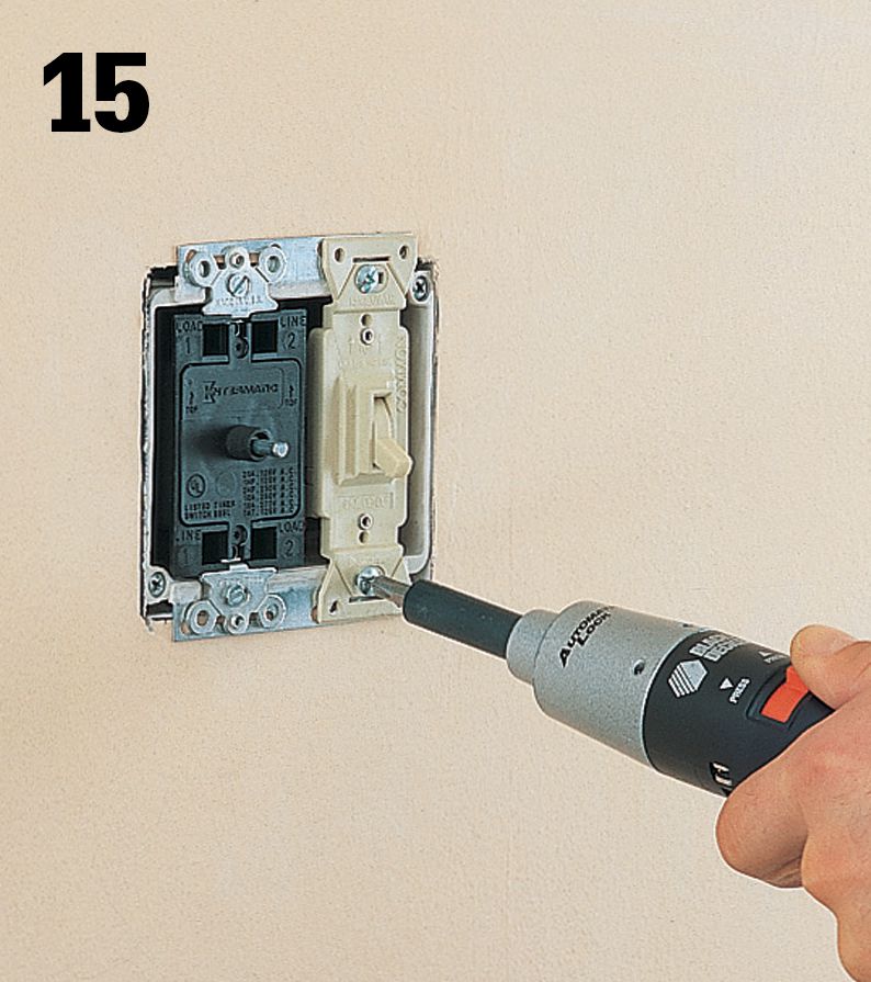
Tuck the wires into the switch box, and then attach the switch and timer to the box. Attach the cover plate and timer dial. Turn on the power.
![]() Range Hoods
Range Hoods
Range hoods do more than just get rid of cooking odors. Their most important job is to reduce the amount of water vapor in the air that’s generated by routine cooking. The pot of water that boils for 30 minutes before you remember to drop in the pasta adds a lot of water vapor into your house. Usually the results are innocent enough. But prolonged periods of high moisture can lead to mildew and other molds that can stain your walls and ceilings and possibly make family members sick.
The hardest part of adding a range hood is installing the ductwork between the hood and the outside of your house. Always use galvanized steel, copper, or stainless steel ducts. Never use flexible duct, including flexible metal duct. If the range is located on an outside wall, the best choice is to run the duct from the back of the hood straight through the wall. If you have wood siding, this job is not difficult. But if you have brick or stone, plan on spending several hours to cut this hole.
If the range is on an interior wall, the preferred route is usually from the top of the hood through the roof. It’s also possible to put the duct into the attic, then across the ceiling (between two rafters or trusses) and out through an overhanging soffit. Follow the hood manufacturer’s instructions about the size and length of the duct. A duct that is too long or too small will not work well and may be a grease fire hazard.
National codes require that a dedicated 20-amp, 120-circuit serve a range hood. You may not draw power from existing circuits. If your range hood includes a microwave oven, be sure to read the installation instructions, preferably before you buy the microwave. You may need a different cabinet above the range. Inspectors may not approve microwaves that are too close to the range.
Tools & Materials ![]()
Hammer
Jigsaw
Screwdrivers Drill/driver & bits
Utility knife
Circular saw
Caulk gun
Exhaust exterior termination
Rangehood
Galvanized sheet metal ducts and fittings
Wire connectors
Sheet metal screws
Foil tape
Plastic roof cement
Caulk
Eye protection
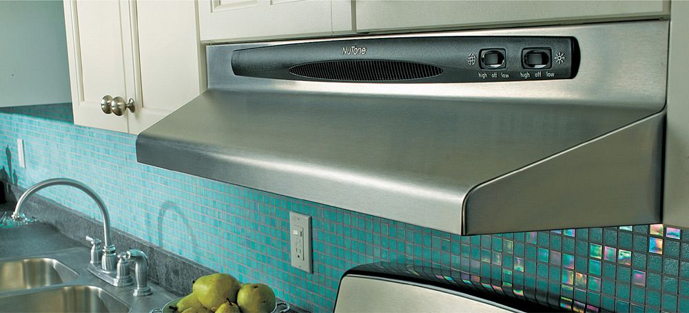
A range hood captures steam and airborne food particles and draws them directly out of your house through an exhaust duct. For slide-in ranges, the hood usually is installed under a short cabinet that contains the ductwork connection.
![]() Range Hoods
Range Hoods
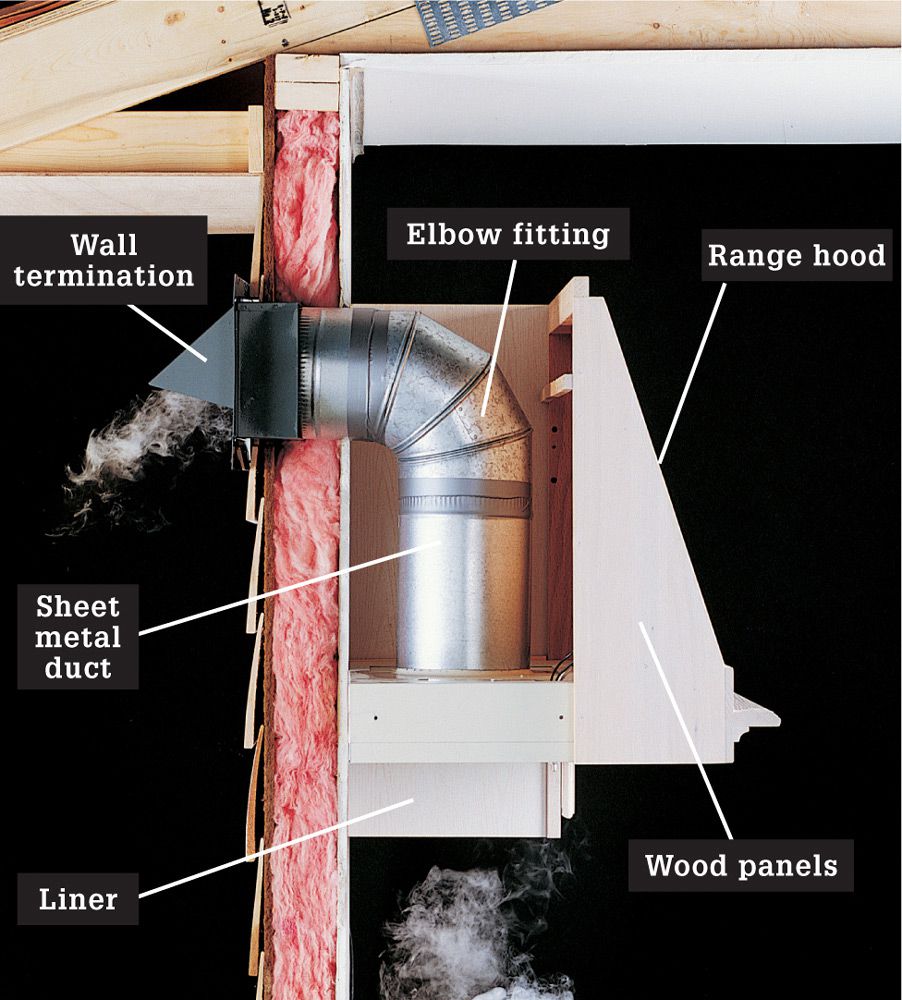
Cabinet-mounted range hoods draw steam upward and out of the house through a wall-mounted or roof-mounted termination.
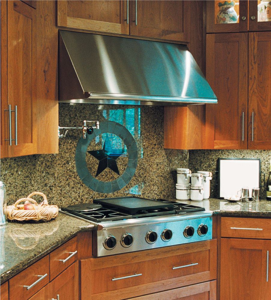
Wall-mounted range hoods function in the same manner as cabinet mounted, but they are not integrated into the kitchen cabinet system.
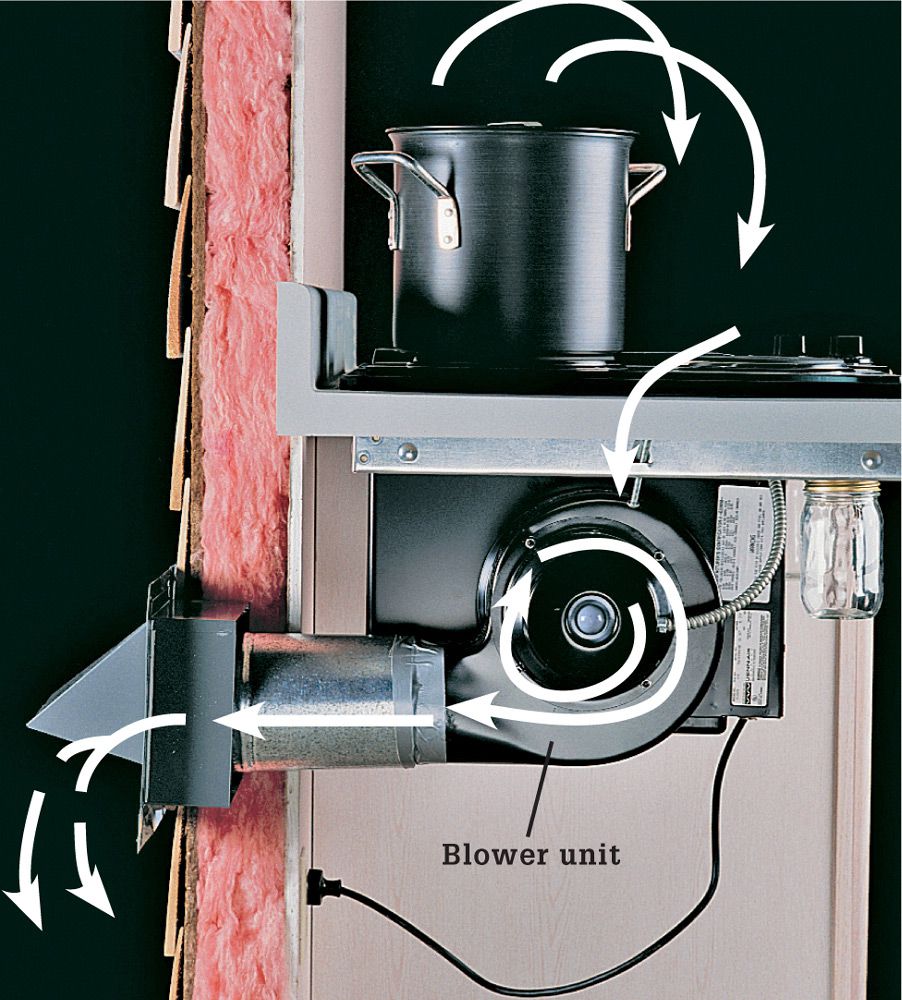
Downdraft exhaust pulls steam downward and exhausts it out through a wall exhaust. While leaving the space above the stovetop uncluttered, these exhausts are much less efficient (in large part because steam naturally rises).

Island exhausts hang down from ceiling-mounted ductwork and draw steam and odors up from stovetops that are installed in kitchen islands. They typically have a very contemporary appearance.
![]() How to Install a Range Hood
How to Install a Range Hood
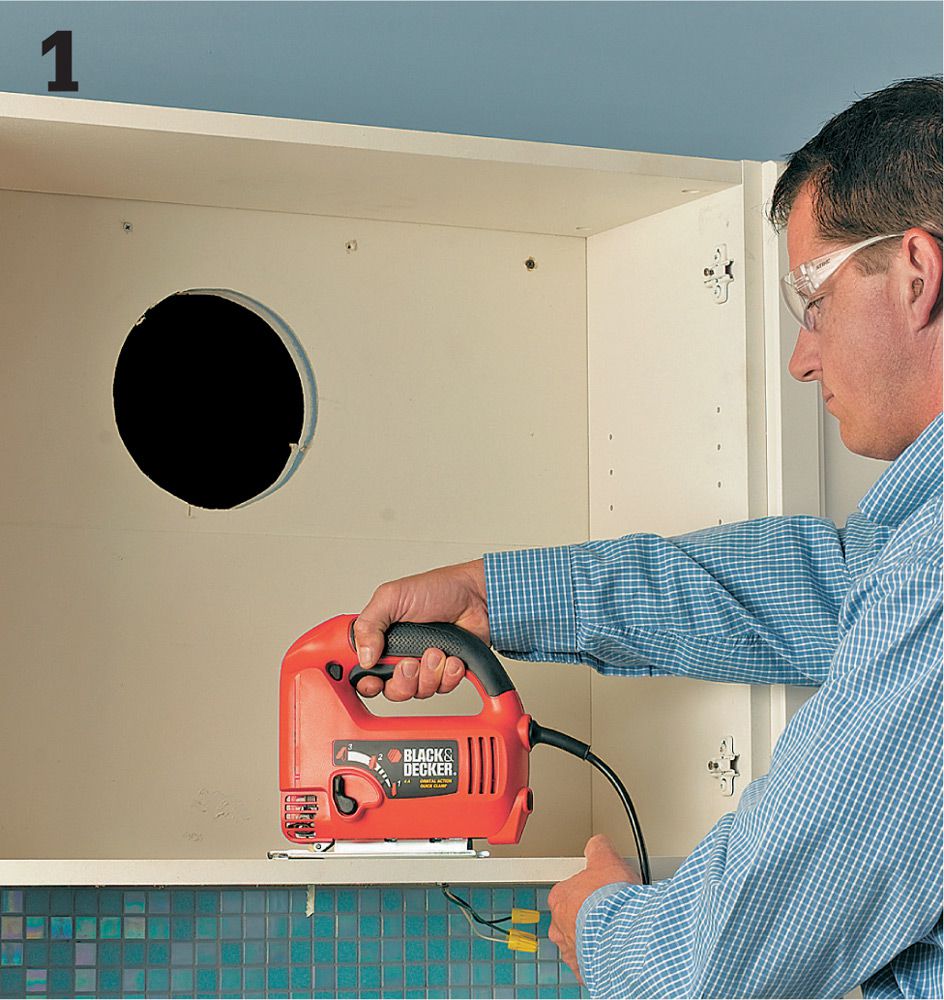
Install the sheet metal duct in the wall first, and then cut a hole in the back of the range hood cabinet and mount the cabinet over the duct. Cut a hole in the bottom of the cabinet to match the opening on the top of the hood. The range hood often comes with templates to help you cut holes in the right place.
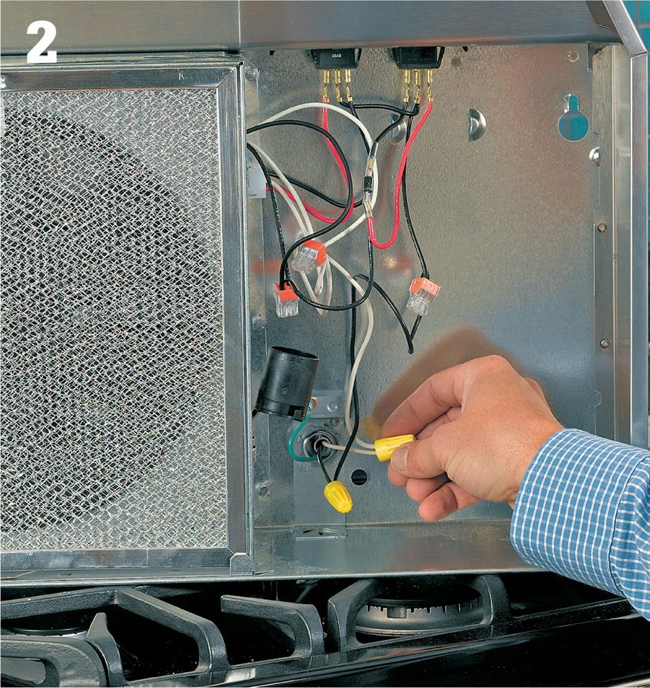
Make sure the circuit power is turned off at the service panel, and test for power. Then join the power cable wires to the lead wires inside the range hood. Use wire connectors for this job.
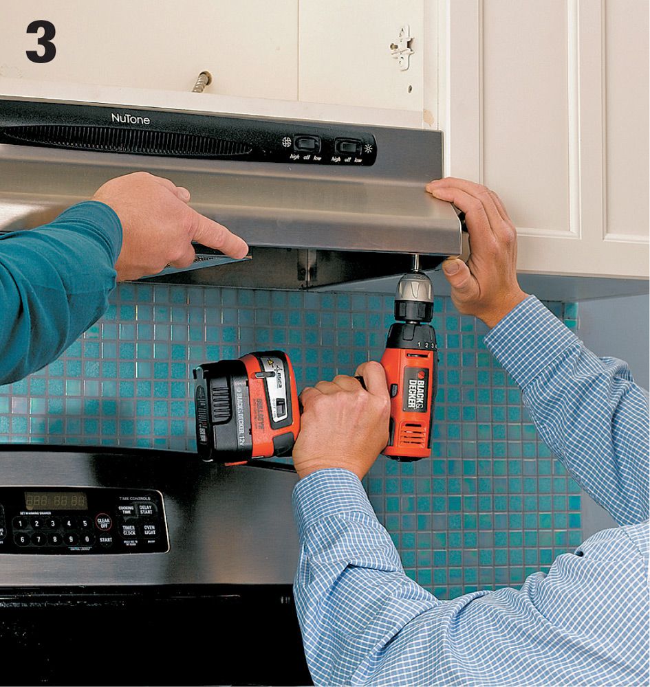
Get someone to help lift the range hood into place and hold it there while you attach it. Drive two screws through both sides and into the adjacent cabinets. If the hood is slightly small for the opening, slip a shim between the hood and the walls, trying to keep the gaps even.
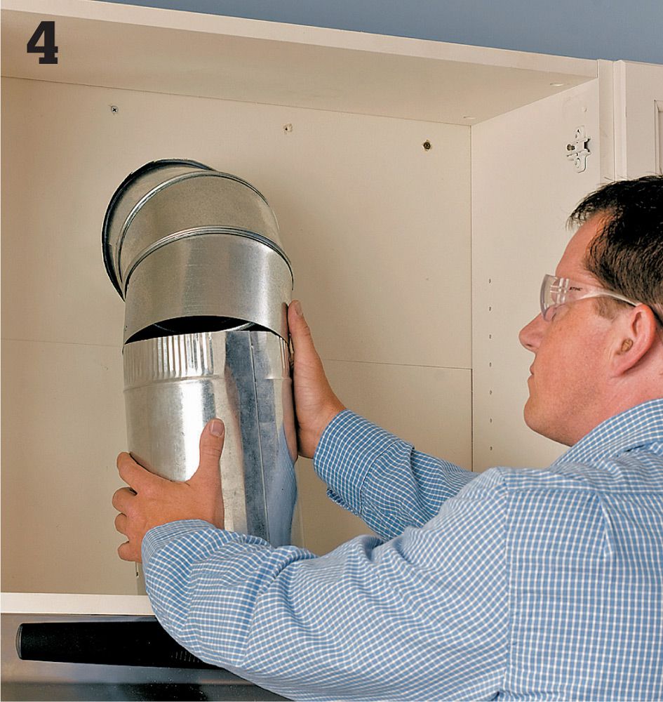
Run ductwork from the cabinet to the exhaust exit point. Use two 45° adjustable elbows to join the duct in the wall to the top of the range hood. Use sheet metal screws and foil tape to hold all parts together and keep them from moving. Connect the duct securely to the fan outlet, and connect all sections so they do not leak. A leaky connection can allow grease-laden air to collect on the wood and start a fire.
![]() Exhaust Termination Locations
Exhaust Termination Locations
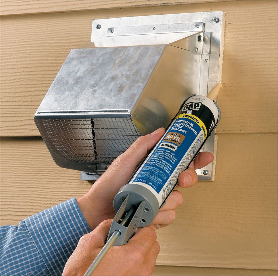
Wall termination: If the duct comes out through the sidewall of the house, install a vertical termination hood. Make sure to seal around the perimeter of the hood with exterior caulk. Don’t locate the termination too close to a window, or the fumes will circulate back into the home.
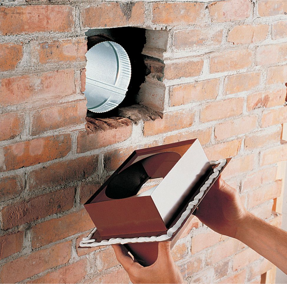
Masonry wall termination: You can run ductwork out through an exterior wall made of brick or stucco, but it is a lot of work. You need to cut an opening in the wall with a masonry saw or chip one with a cold chisel, and then attach the termination hood with masonry nails.
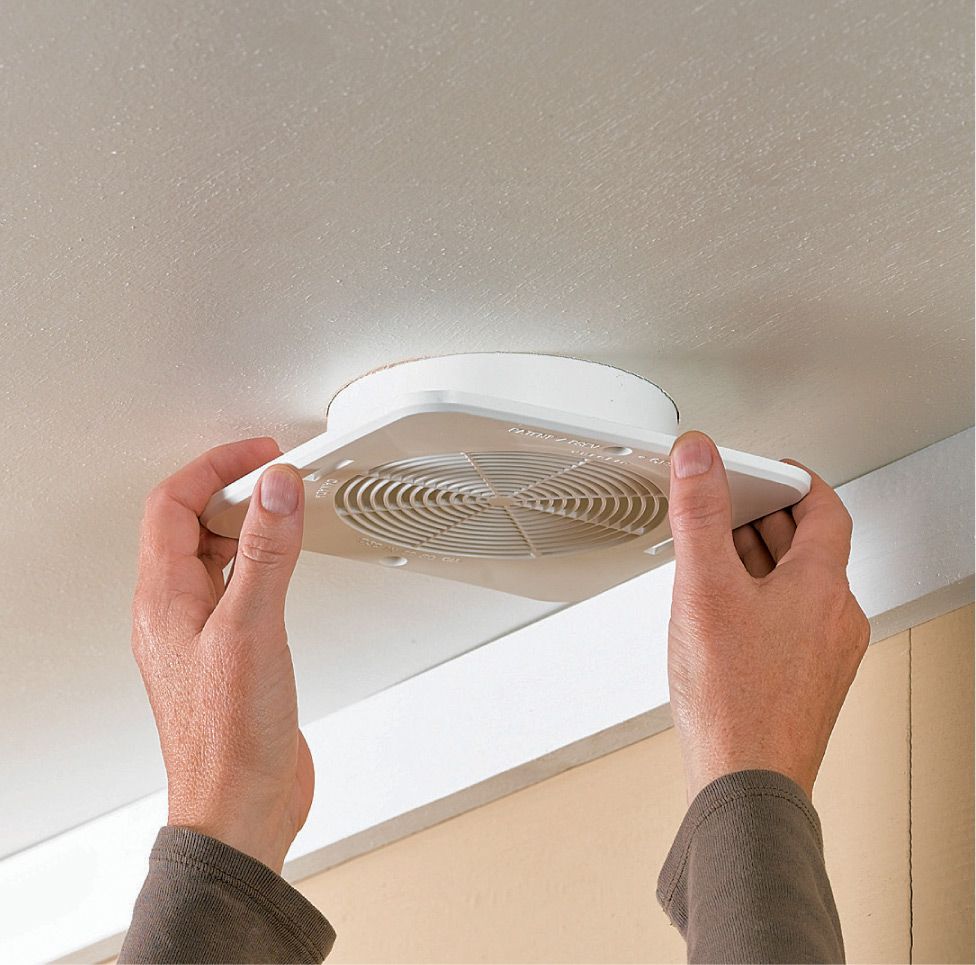
Soffit termination: If the duct goes through an overhang soffit, you’ll need a transition fitting to connect the round duct to a short piece of rectangular duct. Once these parts are installed, add a protective grille to keep animals and insects from getting into the duct. Don’t locate the termination near a soffit ventilation opening; the fumes and moisture will be drawn back into the attic.
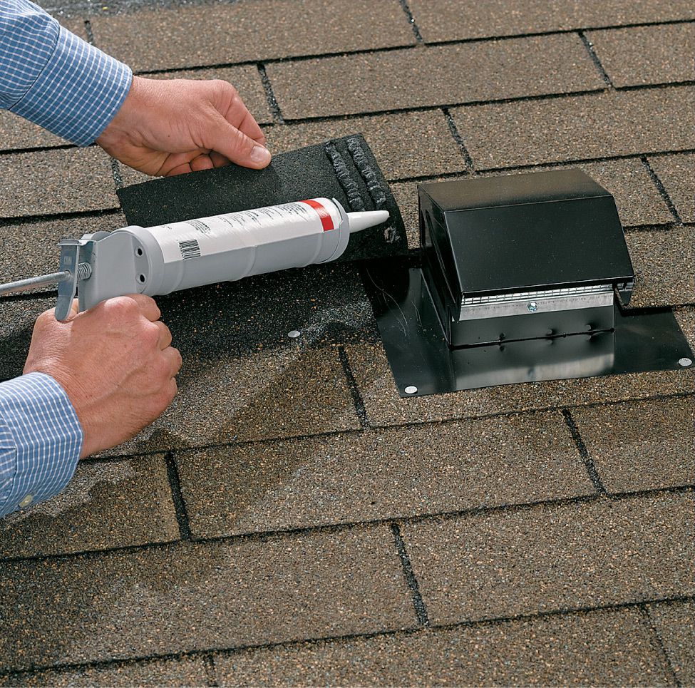
Roof termination: For ducts that pass through the roof, cut an access hole through the roofing and sheathing, and then install a weatherproof cap on top of the duct and under the roofing shingles. Make a waterproof seal by caulking the cap with plastic roof cement. If you don’t have much roofing experience, consult a roofing manual for some more information on this step. Have a roofer do this is you have a roof covering other than shingles or if your roof is steep or high. Also see page 254.
![]() Backup Power Supply
Backup Power Supply
Installing a backup generator is an invaluable way to prepare your family for emergencies. The simplest backup power system is a portable gas-powered generator and an extension cord or two. A big benefit of this approach is that you can run a refrigerator and a few worklights during a power outage with a tool that can also be transported to remote job sites or on camping trips when it’s not doing emergency backup duty. This is also the least expensive way to provide some backup power for your home. You can purchase a generator at most home centers and be up and running in a matter of hours. If you take this approach, it is critically important that you make certain any loads being run by your generator are disconnected from the utility power source.
The next step up is to incorporate a manual transfer switch for your portable generator. Transfer switches are permanently hardwired to your service panel. They are mounted on either the interior or the exterior of your house between the generator and the service panel. You provide a power feed from the generator into the switch. The switch is wired to selected essential circuits in your house, allowing you to power lights, furnace blowers, and other loads that can’t easily be run with an extension cord. But perhaps the most important job a transfer switch performs is to disconnect the utility power. If the inactive utility power line is attached to the service panel, “backfeed” of power from your generator to the utility line can occur when the generator kicks in. This condition could be fatal to line workers who are trying to restore power. The potential for backfeed is the main reason many municipalities insist that only a licensed electrician hook up a transfer switch. Using a transfer switch not installed by a professional may also void the warranty of the switch and the generator.
Automatic transfer switches turn on the generator and switch off the utility supply when they detect a significant drop in line voltage. They may be installed with portable generators, provided the generator is equipped with an electric starter.
Large standby generators that resemble central air conditioners are the top of the line in backup power supply systems. Often fueled by home natural gas lines or propane tanks that offer a bottomless fuel source, standby generators are made in sizes with as much as 20 to 40 kilowatts of output—enough to supply all of the power needs of a 5,000-sq.-ft. home.
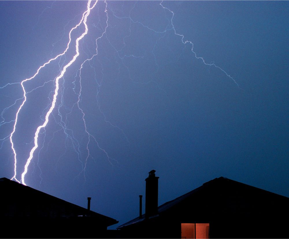

Generators have a range of uses. Large hard-wired models can provide instant emergency power for a whole house. Smaller models are convenient for occasional short-term backup as well as job sites or camping trips.
![]() Choosing a Backup Generator
Choosing a Backup Generator
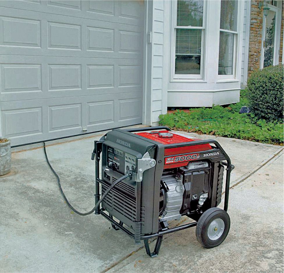
A 2,000- to 5,000-watt gas-powered generator and a few extension cords can power lamps and an appliance or two during shorter-term power outages. Appliances must not be connected to household wiring and the generator simultaneously. Never plug a generator into an outlet. Never operate a generator indoors. Run extension cords through a garage door.
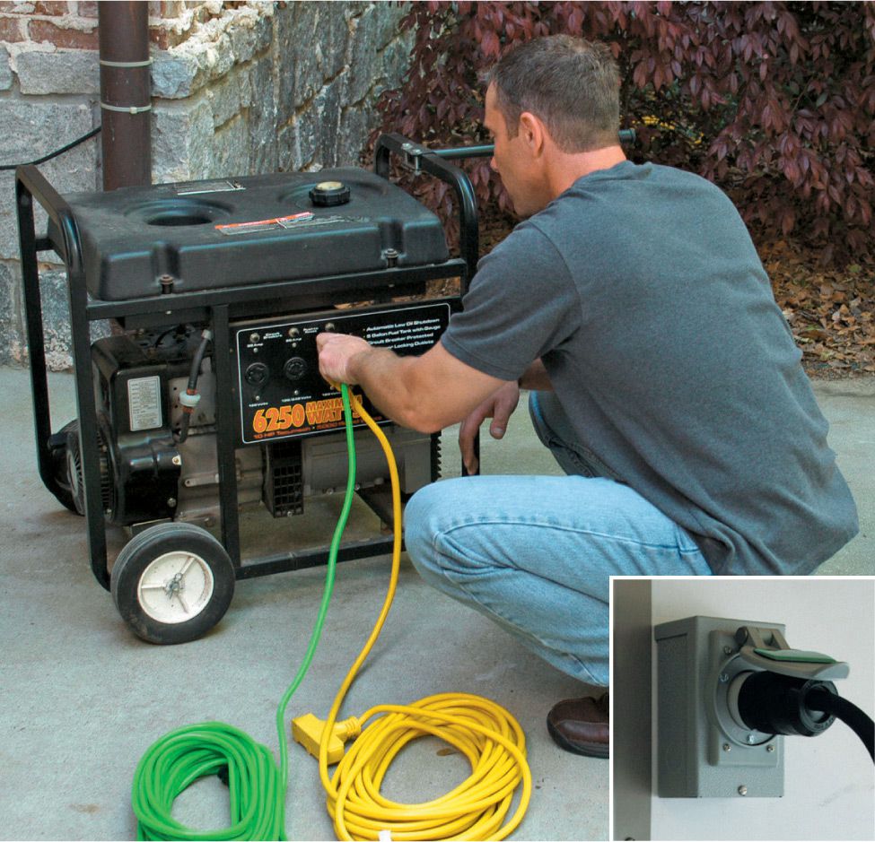
A permanent transfer switch patches electricity from a large portable generator through to selected household circuits via an inlet at your service panel (inset), allowing you to power hardwired fixtures and appliances with the generator.
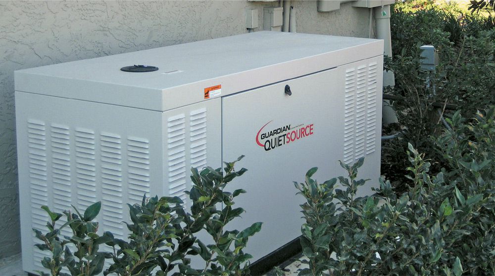
For full, on-demand backup service, install a large standby generator wired through to an automatic transfer panel. In the event of a power outage, the household system instantly switches to the generator.
![]() A Typical Backup System
A Typical Backup System
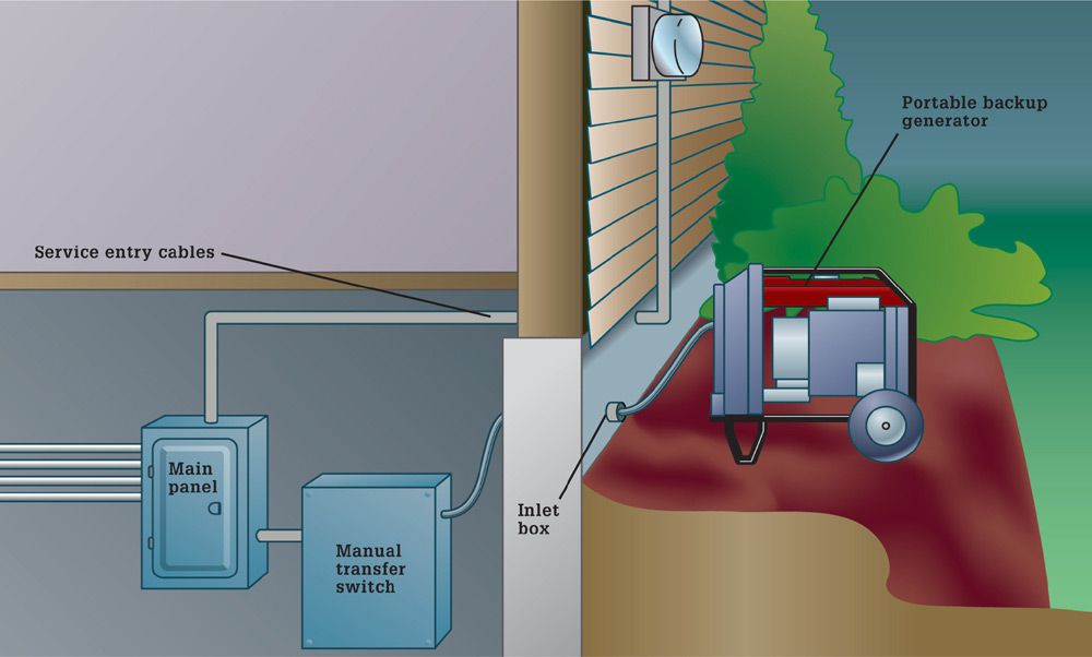
Backup generators supply power to a manual transfer switch, which disconnects the house from the main service wires and routes power from the generator through selected household circuits.
![]() Choosing a Generator
Choosing a Generator
Choosing a generator for your home’s needs requires a few calculations. The chart below gives an estimate of the size of generator typically recommended for a house of a certain size. You can get a more accurate number by adding up the power consumption (the watts) of all the circuits or devices to be powered by a generator. It’s also important to keep in mind that, for most electrical appliances, the amount of power required at the moment you flip the ON switch is greater than the number of watts required to keep the device running. For instance, though an air conditioner may run on 15,000 watts of power, it will require a surge of 30,000 watts at startup (the power range required to operate an appliance is usually listed somewhere on the device itself). These two numbers are called run watts and surge watts. Generators are typically sold according to run watts (a 5,000-watt generator can sustain 5,000 watts). They are also rated for a certain number of surge watts (a 5,000-watt generator may be able to produce a surge of 10,000 watts). If the surge watts aren’t listed, ask, or check the manual. Some generators can’t develop many more surge watts than run watts; others can produce twice as much surge as run wattage.
It’s not necessary to buy a generator large enough to match the surge potential of all your circuits (you won’t be turning everything on simultaneously), but surge watts should factor in your purchasing decision. If you will be operating the generator at or near capacity, it is also a wise practice to stagger startups for appliances.
|
Size of House (in square feet) |
Recommended generator size (in kilowatts) |
|
Up to 2,700 |
5-11 |
|
2,701-3,700 |
14-16 |
|
3,701-4,700 |
20 |
|
4,701-7,000 |
42-47 |
![]() Types of Transfer Switches
Types of Transfer Switches
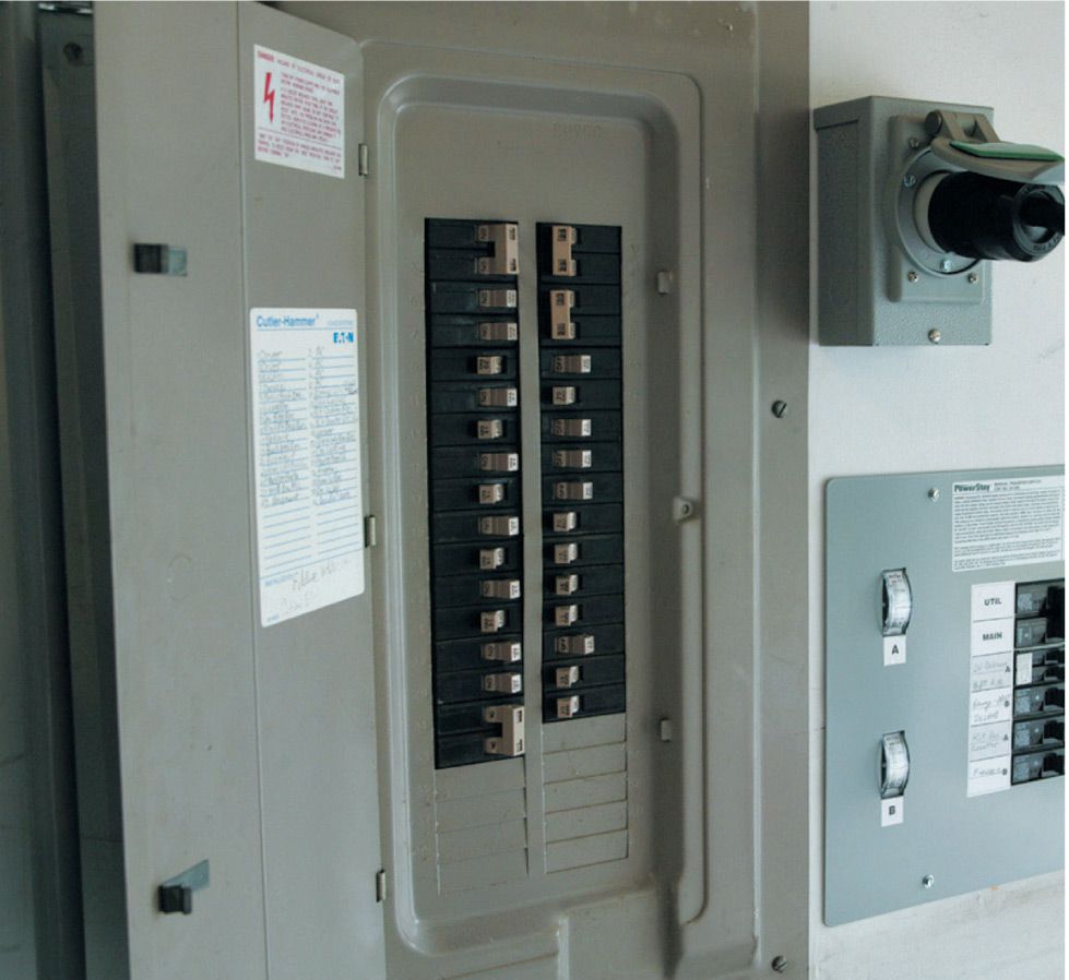
Cord-connected transfer switches (shown above) are hard-wired to the service panel (in some cases they’re installed after the service panel and operate only selected circuits). These switches contain a male receptacle for a power supply cord connected to the generator. Automatic transfer switches (not shown) detect voltage drop-off in the main power line and switch over to the emergency power source.
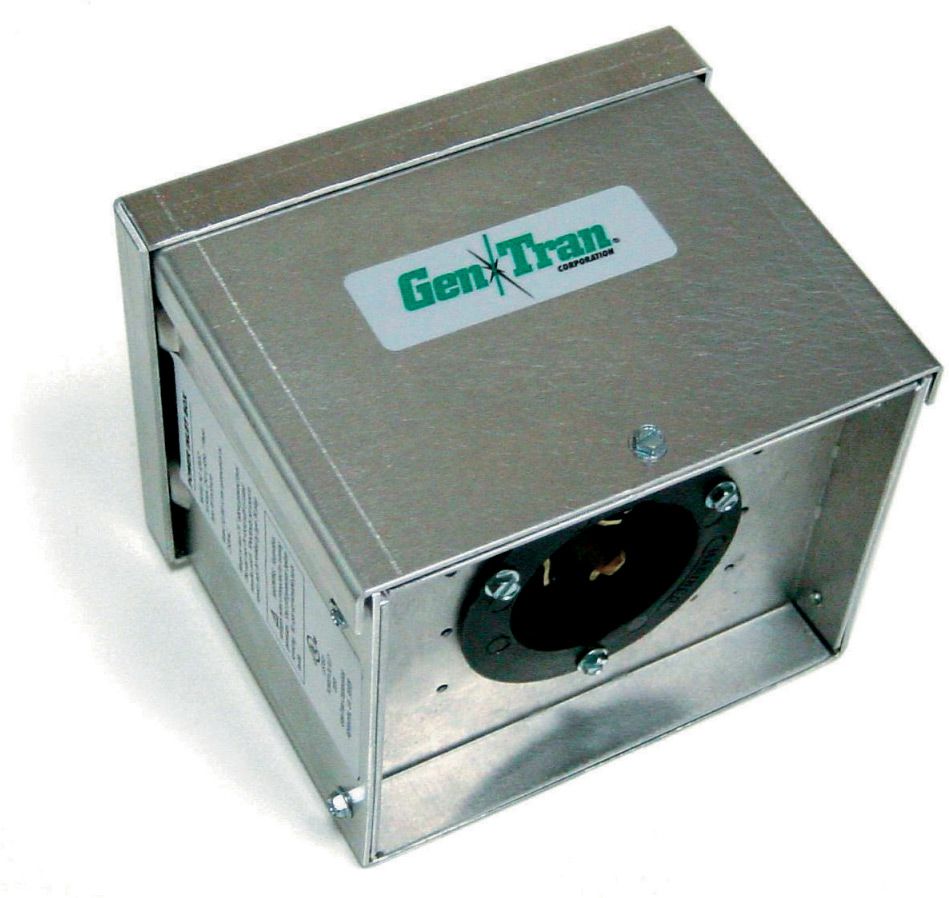
When using a cord-connected switch, consider mounting an inlet box to the exterior wall. This will allow you to connect a generator without running a cord into the house.
Generator Tips ![]()
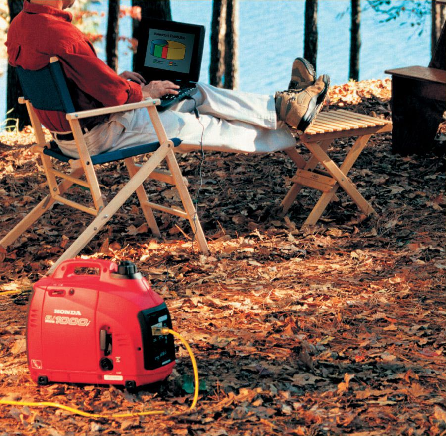
If you’ll need to run sensitive electronics such as computers or home theater equipment, look for a generator with power inverter technology that dispenses “clean power” with a stable sine wave pattern.
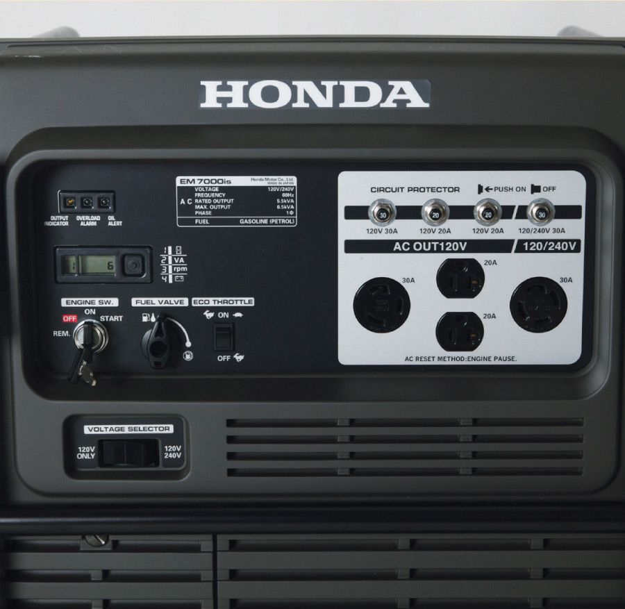
A generator that will output 240-volt service is required to run most central air conditioners. If your generator has variable output (120/240) make sure the switch is set to the correct output voltage.
![]() Running & Maintaining a Backup System
Running & Maintaining a Backup System
Even with a fully automatic standby generator system fueled by natural gas or propane, you will need to conduct some regular maintenance and testing to make sure all systems are ready in the event of power loss. If you’re depending on a portable generator and extension cords or a standby generator with a manual transfer switch, you’ll also need to know the correct sequence of steps to follow in a power emergency. Switches and panels also need to be tested on a regular basis, as directed in your owner’s manual. And be sure that all switches (both interior and exterior) are housed in an approved enclosure box.
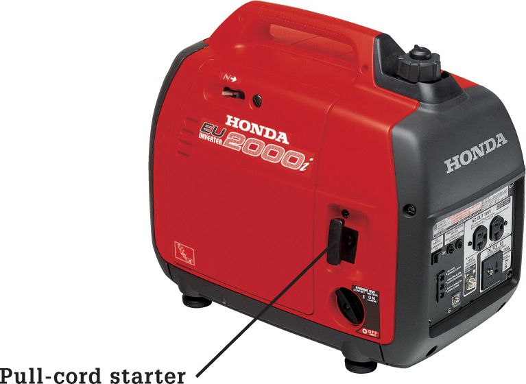
Smaller portable generators often use pull-cords instead of electric starters.
ANATOMY OF A PORTABLE BACKUP GENERATOR

Portable generators use small gasoline engines to generate power. A built-in electronics panel sets current to AC or DC and the correct voltage. Most models will also include a built-in circuit breaker to protect the generator from damage in the event it is connected to too many loads. Better models include features like built-in GFCI protection. Larger portable generators may also feature electric starter motors and batteries for push-button starts.
![]() Operating a Manual System During an Outage
Operating a Manual System During an Outage
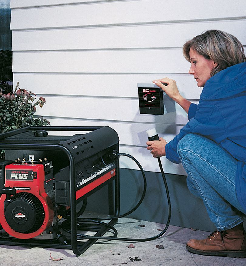
Plug the generator in at the inlet box. Make sure the other end of the generator’s outlet cord is plugged into the appropriate outlet on the generator (120-volt or 120/240-volt AC) and the generator is switched to the appropriate voltage setting.
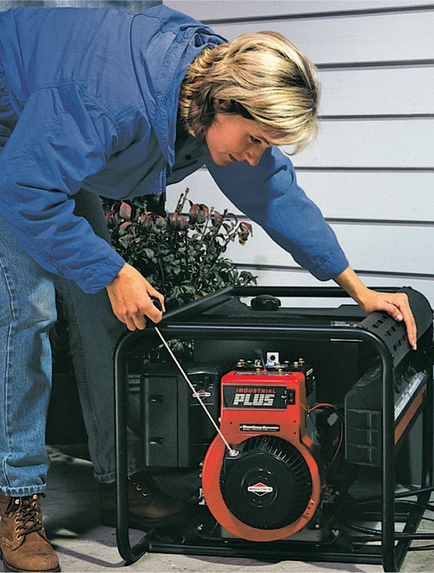
Start the generator with the pull-cord or electric starter (if your generator has one). Let the generator run for several minutes before flipping the transfer switch.
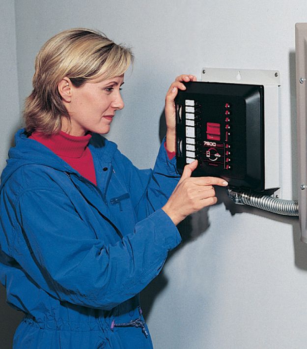
Flip the manual transfer switch. Begin turning on loads one at a time by flipping breakers on, starting with the ones that power essential equipment. Do not overload the generator or the switch, and do not run the generator at or near full capacity for more than 30 minutes at a time.
![]() Maintaining & Operating an Automatic Standby Generator
Maintaining & Operating an Automatic Standby Generator

If you choose to spend the money and install a dedicated standby generator of 10,000 watts or more and operate it through an automatic transfer switch or panel, you won’t need to lift a hand when your utility power goes out. The system kicks in by itself. However, you should follow the manufacturer’s instructions for testing the system, changing the oil, and running the motor periodically.
![]() Installing a Transfer Switch
Installing a Transfer Switch
Atransfer switch is installed next to the main service panel to override the normal electrical service with power from a backup generator during a power outage. Manual transfer switches require an operator to change the power source, while automatic switches detect the loss of power, start the back-up generator, and switch over to the backup power feed. Because the amount of electricity created by a backup generator is not adequate to power all of the electrical circuits in your house, you’ll need to designate a few selected circuits to get backup current (see page267).
Tools & Materials ![]()
Circuit tester
Drill/driver
Screwdrivers
Hammer
Wire cutters
Cable ripper
Wire strippers
Level
Manual transfer switch
Screws
Wire connectors (yellow)
Standby power generator
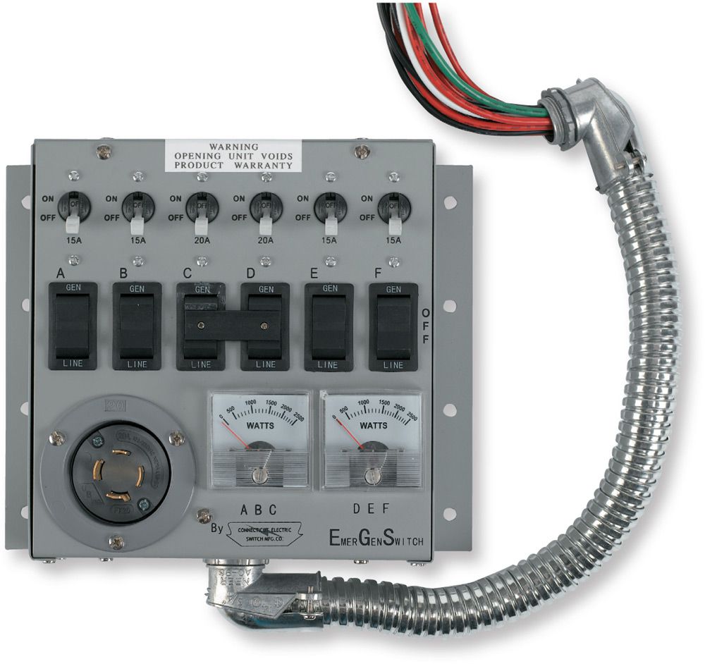
A manual transfer switch connects emergency circuits in your main panel to a standby generator.
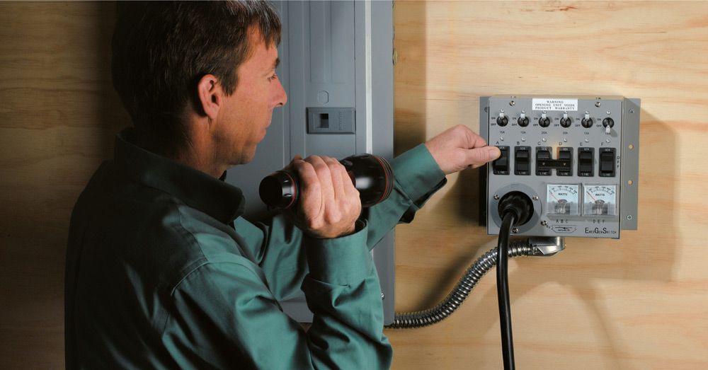
One flip of a switch reassigns the power source for each critical circuit so your backup generator can keep your refrigerator, freezer, and important lights running during an outage of utility power.
Selecting Backup Circuits ![]()
Before you purchase a backup generator, determine which loads you will want to power from your generator in the event of a power loss. Generally you will want to power your refrigerator, freezer, and maybe a few lights. Add up the running wattage ratings of the appliances you will power up to determine how large your backup generator needs to be. Because the startup wattage of many appliances is higher than the running wattage, avoid starting all circuits at the same time—it can cause an overload situation with your generator. Here are some approximate running wattage guidelines (see page 132 to 137 for more information on calculating electrical loads):
✵ Refrigerator: 750 watts
✵ Forced air furnace: 1,100 to 1,500 watts
✵ Incandescent lights: 60 watts per bulb (CFL and LED lights use less wattage)
✵ Sump pump: 800 to 1,000 watts
✵ Garage door opener: 550 to 1,100 watts
✵ Television: 300 watts
Add the wattage values of all the loads you want to power, and multiply the sum by 1.25. This will give you the minimum wattage your generator must produce. Portable standby generators typically output 5,000 to 7,500 watts. Most larger, stationary generators can output 10,000 to 20,000 watts (10 to 20 kilowatts).
![]() How to Install a Manual Transfer Switch
How to Install a Manual Transfer Switch
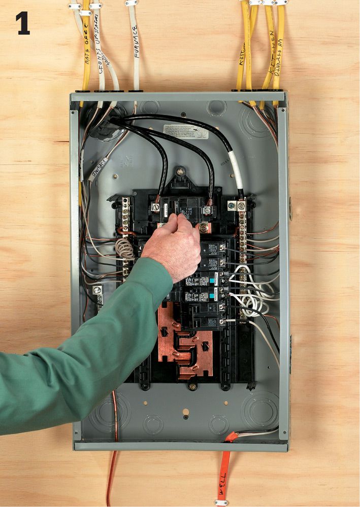
Turn off the main power breaker in your electrical service panel. CAUTION: The terminals where power enters the main breakers will still be energized.
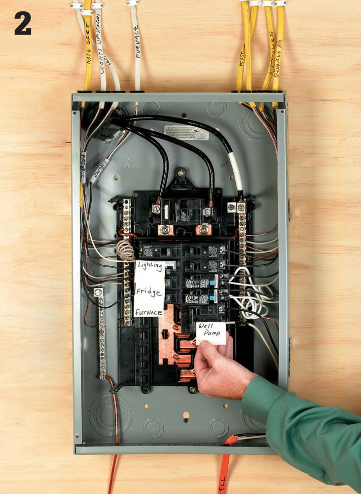
Determine which household circuits are critical for emergency usage during a power outage. Typically this will include the refrigerator, freezer, furnace, and at least one light or small appliance circuit.
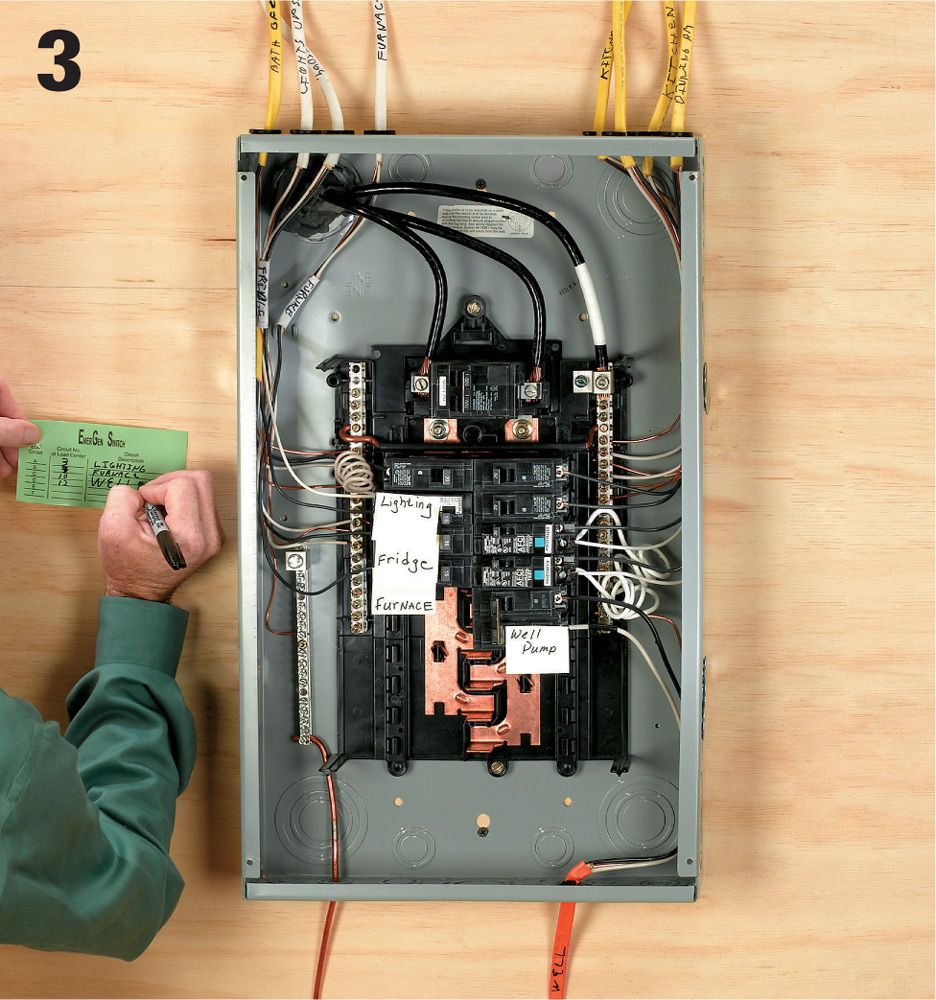
Match your critical circuits with circuit inlet on your pre-wired transfer switch. Try to balance the load as best you can in the transfer switch: For example, if your refrigerator is on the leftmost switch circuit, connect your freezer to the circuit farthest to the right. Double-pole (240-volt) circuits will require two 120-volt circuit connections. Also make sure that 15-amp and 20-amp circuits are not mismatched with one another.
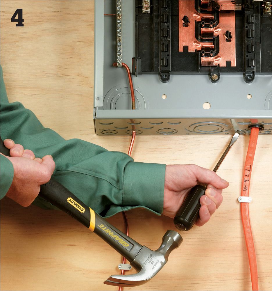
Select and remove a knockout at the bottom of the main service panel box. Make sure to choose a knockout that is sized to match the connector on the flexible conduit coming from the transfer switch.
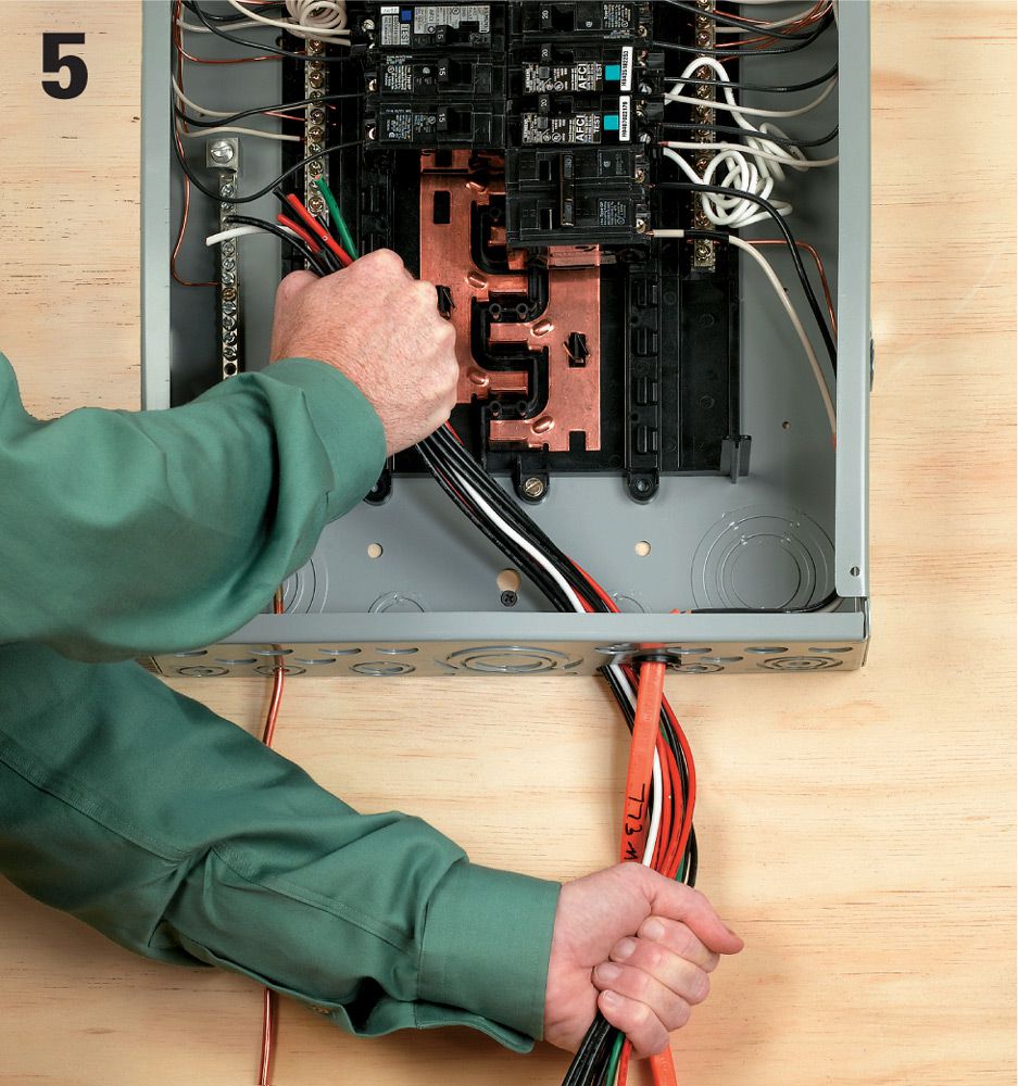
Feed the wires from the transfer switch into the knockout hole, taking care not to damage the insulation. You will note that each wire is labeled according to which circuit in the switch box it feeds.
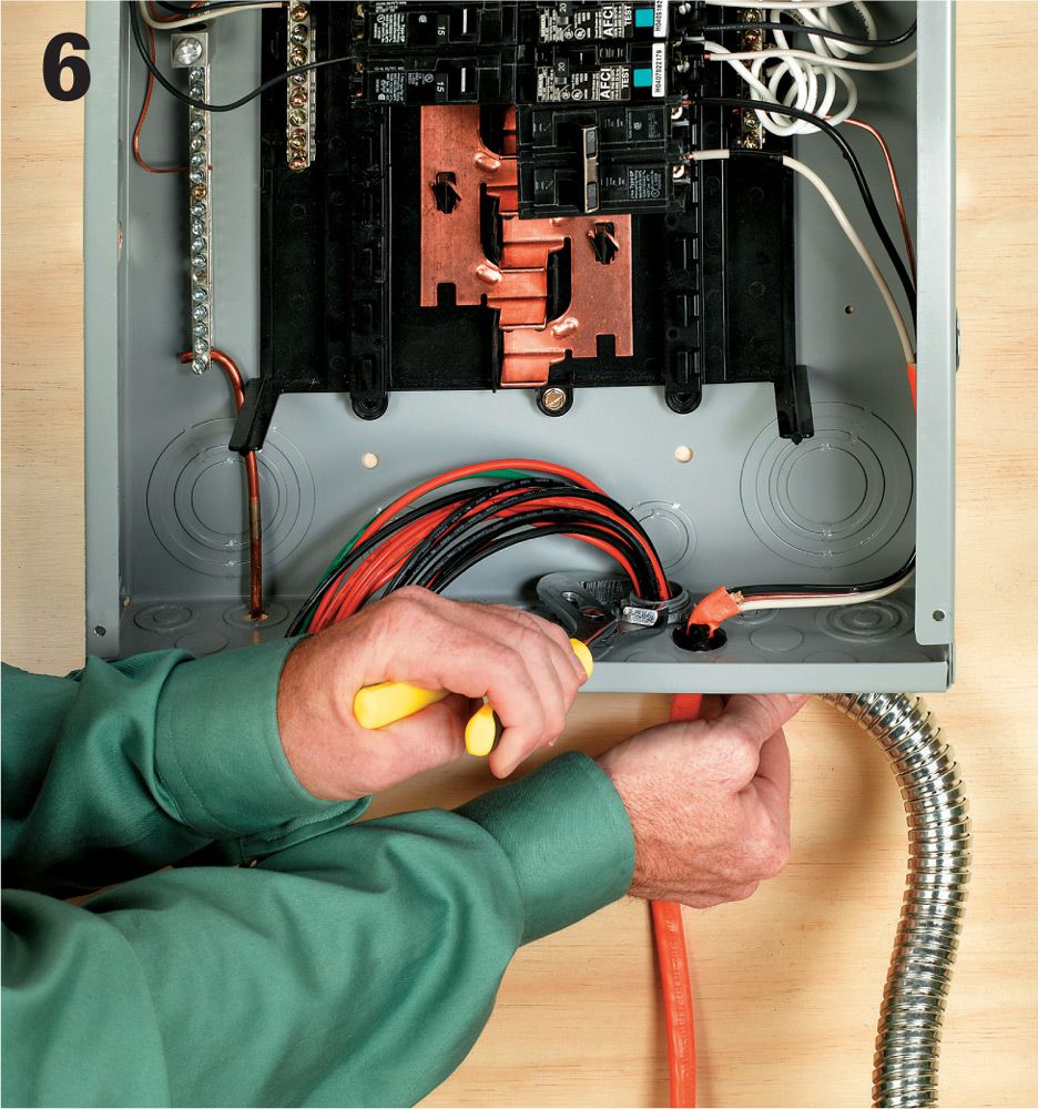
Secure the flexible conduit from the switch box to the main service panel using a locknut and a bushing where required.
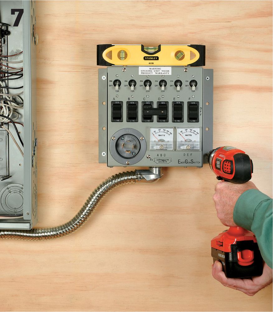
Attach the transfer switch box to the wall so the closer edge is about 18" away from the center of the main service panel. Use whichever connectors make sense for your wall type.
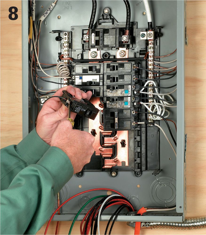
Remove the breaker for the first critical circuit from the main service panel box, and disconnect the hot wire lead from the lug on the breaker.
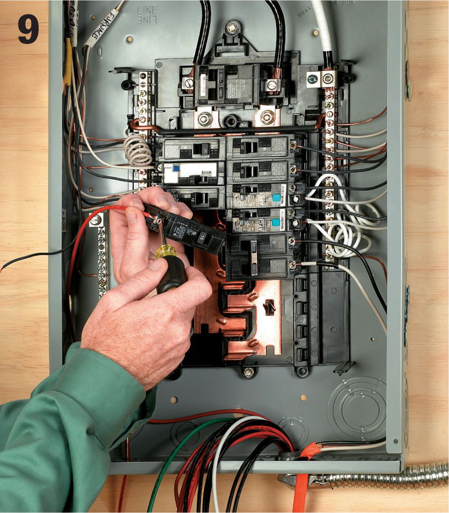
Locate the red wire for the switch box circuit that corresponds to the circuit you’ve disconnected. Attach the red wire to the breaker you’ve just removed, and then reinstall the breaker.
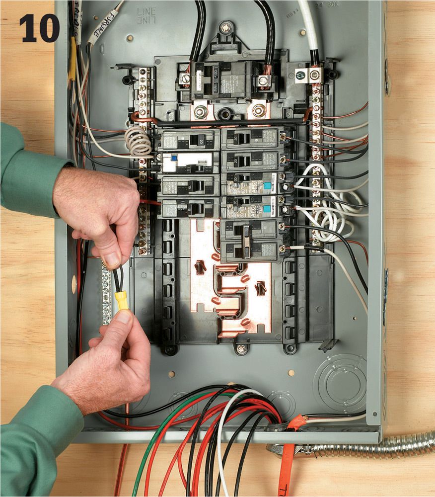
Locate the black wire from the same transfer switch circuit, and twist it together with the old feed wire, using a yellow wire connector. Tuck the wires neatly out of the way at the edges of the box. Proceed to the next circuit, and repeat the process.
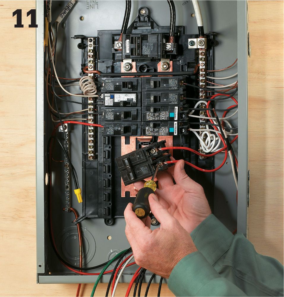
If any of your critical circuits are 240-volt circuits, attach the red leads from the two transfer switch circuits to the double-pole breaker. The two circuits originating in the transfer switch should be next to one another, and their switches should be connected with a handle tie. If you have no 240-volt circuits you may remove the preattached handle tie and use the circuits individually.
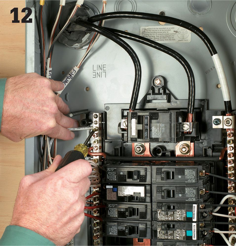
Once you have made all circuit connections, attach the white neutral wire from the transfer switch to an opening in the neutral bus bar of the main service panel.
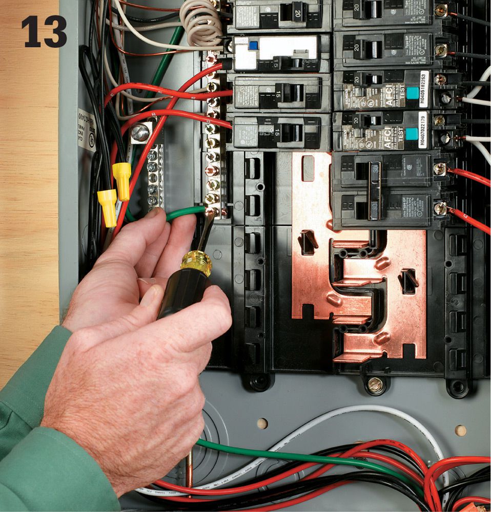
Attach the green ground wire from the transfer switch to an open port on the grounding bar in your main service panel. This should complete the installation of the transfer switch. Replace the cover on the service panel box, and make sure to fill in the circuit map on your switch box.
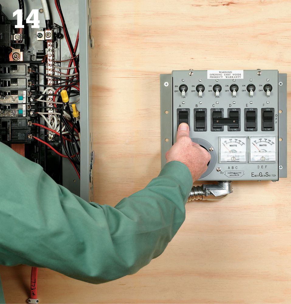
Begin testing the transfer switch by making sure all of the switches on it are set to the LINE setting. The power should still be OFF at the main panel breakers.
Standby Generators ![]()
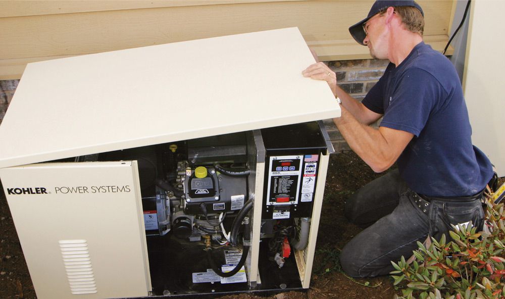
Make sure your standby generator is operating properly and has been installed professionally. See page 262 for information on choosing a generator that is sized appropriately for your needs.
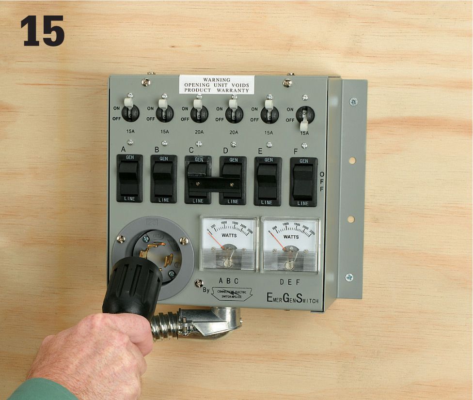
Before turning your generator on, attach the power cord from the generator to the switch box. Never attach or detach a generator cord with the generator running. Turn your standby power generator on, and let it run for a minute or two.
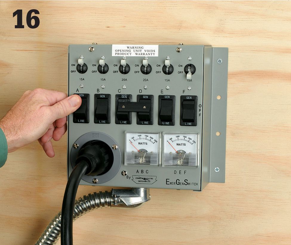
Flip each circuit switch on the transfer switch box to GEN, one at a time. Try to maintain balance by moving back and forth from circuits on the left and right side. Do not turn all circuits on at the same time. Observe the onboard wattage meters as you engage each circuit, and try to keep the wattage levels in balance. When you have completed testing the switch, turn the switches back to LINE, and then shut off your generator.
![]() Outbuildings
Outbuildings
Nothing improves the convenience and usefulness of an outbuilding more than electrifying it. Running a new underground circuit from your house to an outbuilding lets you add receptacles and light fixtures both inside the outbuilding and on its exterior. If you run power to an outbuilding, you are required to install at least one receptacle.
Adding one or two 120-volt circuits is not complicated, but every aspect of the project is strictly governed by local building codes. Therefore, once you’ve mapped out the job and have a good idea of what’s involved, visit your local building department to discuss your plans and obtain a permit for the work.
This project demonstrates standard techniques for running a circuit cable from the house exterior to a shed, plus the wiring and installation of devices inside the shed. To add a new breaker and make the final circuit connections to your home’s main service panel, see page 174. If you run power to an outbuilding, you are required to install at least one receptacle.
First, determine how much current you will need. For basic electrical needs, such as powering a standard light fixture and small appliances or power tools, a 120-volt, 15-amp circuit should be sufficient. A small workshop may require one or two 120-volt, 20-amp circuits. If you need any 240-volt circuits or more than two 120-volt, 20-amp circuits, you will need to install at least a 60-amp subpanel with appropriate feeder wires. Installing a subpanel in an outbuilding is similar to installing one inside your home, but there are some important differences.
You may use #14 copper wire for one 120-volt, 15-amp circuit or #12 copper wire for one 120-volt, 20-amp circuit. Use #10 copper wire for two 120-volt, 20 amp circuits. Also, if the shed is more than 150 ft. away from the house, you may need heavier-gauge cable to account for voltage drop.
Most importantly, don’t forget to call before you dig. Have all utility and service lines on your property marked even before you make serious project plans. This is critical for your safety of course, and it may affect where you can run the circuit cable.
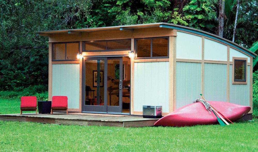
Adding an electrical circuit to an outbuilding such as this shed greatly expands the activities the building will support and is also a great benefit for home security.
Tools & Materials ![]()
Spray paint
Trenching shovel (4" wide blade)
4" metal junction box
Metal L-fittings (2) and conduit nipple for conduit
Wood screws
Conduit with watertight threaded and compression fittings
Wrenches
Hacksaw
90° sweeps for conduit (2)
Plastic conduit bushings (2)
Pipe straps
Silicone caulk and caulk gun
Double-gang boxes, metal (2)
One exterior receptacle box (with cover)
Single-pole switches (2)
Interior ceiling light fixture and metal fixture box
Exterior motion-detector fixture and plastic fixture box
EMT metal conduit and fittings for inside the shed
Utility knife
UF two-wire cable (12 gauge)
THNN wire (12 gauge)
20-amp GFCI- protected circuit breaker
Wire stripper
Pliers
Screwdrivers
Wire connectors
Hand tamper
Schedule 80 conduit
Eye protection
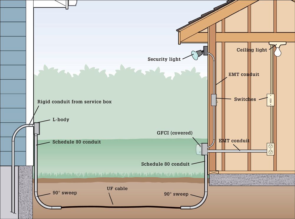
A basic outdoor circuit starts with a waterproof fitting at the house wall connected to a junction box inside. The underground circuit cable—rated UF (underground feeder)—runs in a 24"-deep trench and is protected from exposure at both ends by metal or PVC conduit. Inside the shed, standard NM cable runs through metal conduit to protect it from damage (not necessary if you will be adding interior wallcoverings). All receptacles in the shed must be GFCI protected.
![]() How to Wire an Outbuilding
How to Wire an Outbuilding
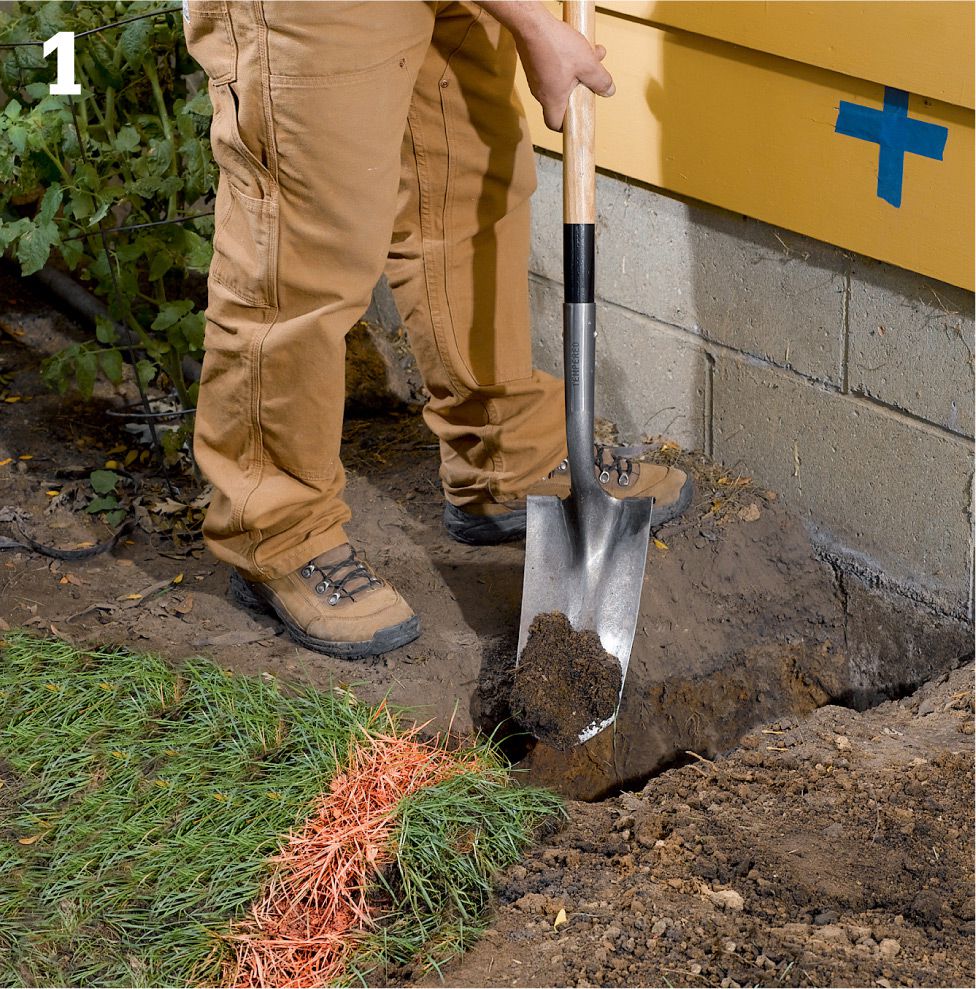
Identify the circuit’s exit point at the house and entry point at the shed and mark them. Mark the path of the trench between the exit and entry points using spray paint. Make the route as direct as possible. Dig the trench to the depth required by local code (24") using a narrow trenching shovel.
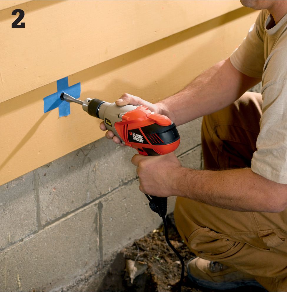
From outside, drill a hole through the exterior wall and the rim joist at the exit point for the cable (you’ll probably need to install a bit extender or an extra-long bit in your drill). Make the hole just large enough to accommodate the L-body conduit fitting and conduit nipple.
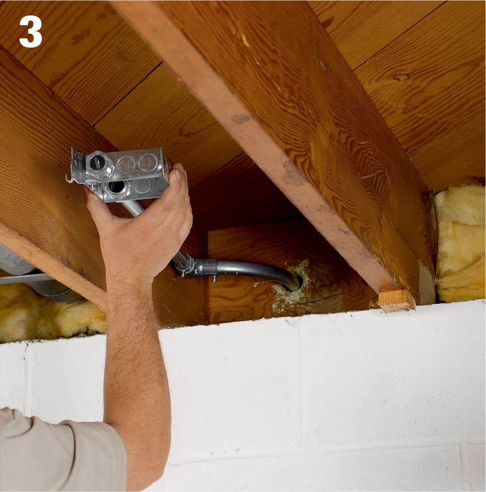
Assemble the conduit and junction box fittings that will penetrate the wall. Here, we attached a 12" piece of 3/4" IMC (intermediate metallic conduit) and a sweep to a metal junction box with a compression fitting and then inserted the conduit into the hole drilled in the rim joist. The junction box is attached to the floor joist.
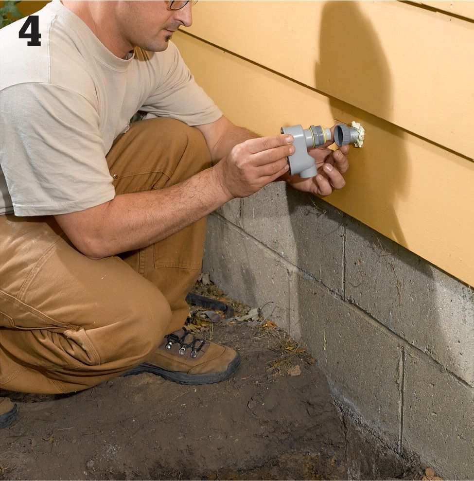
From outside, seal the hole around the conduit with expandable spray foam or caulk, and then attach the free end of the conduit to the back of a waterproof L-body fitting. Mount the L-body fitting to the house exterior with the open end facing downward.
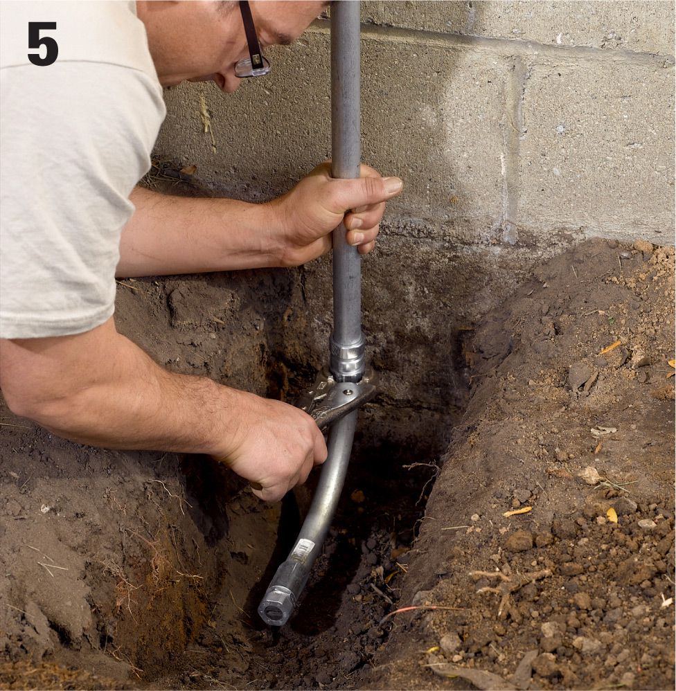
Cut a length of IMC to extend from the L-fitting down into the trench using a hacksaw. Deburr the cut edges of the conduit. Secure the conduit to the L-fitting, and then attach a 90° sweep to the bottom end of the conduit using compression fittings. Add a bushing to the end of the sweep to protect the circuit cable. Anchor the conduit to the wall with a corrosion-resistant pipe strap.
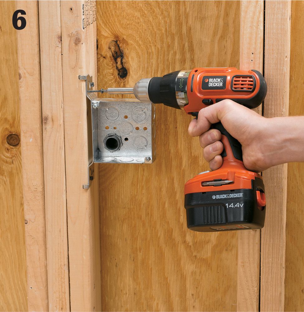
Inside the shed, drill a 3/4" dia. hole in the shed wall. On the interior of the shed, mount a junction box with a knock-out removed to allow the cable to enter through the hole. On the exterior side directly above the end of the UF trench, mount an exterior-rated receptacle box with cover. The plan (and your plan may differ) is to bring power into the shed through the hole in the wall behind the exterior receptacle.
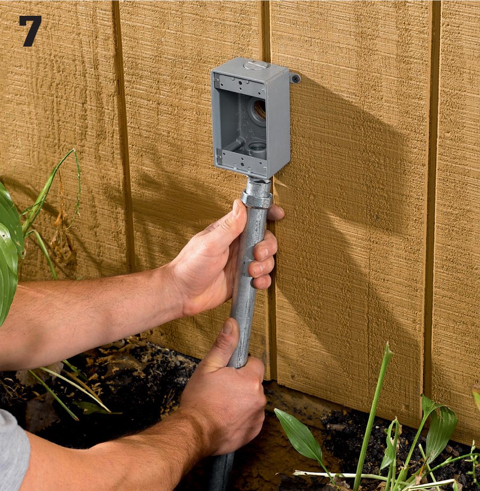
Run conduit from the exterior box down into the trench. Fasten the conduit to the building with a strap. Add a 90° sweep and bushing, as before. Secure the conduit to the box with an offset fitting. Anchor the conduit with pipe straps, and seal the entry hole with caulk.
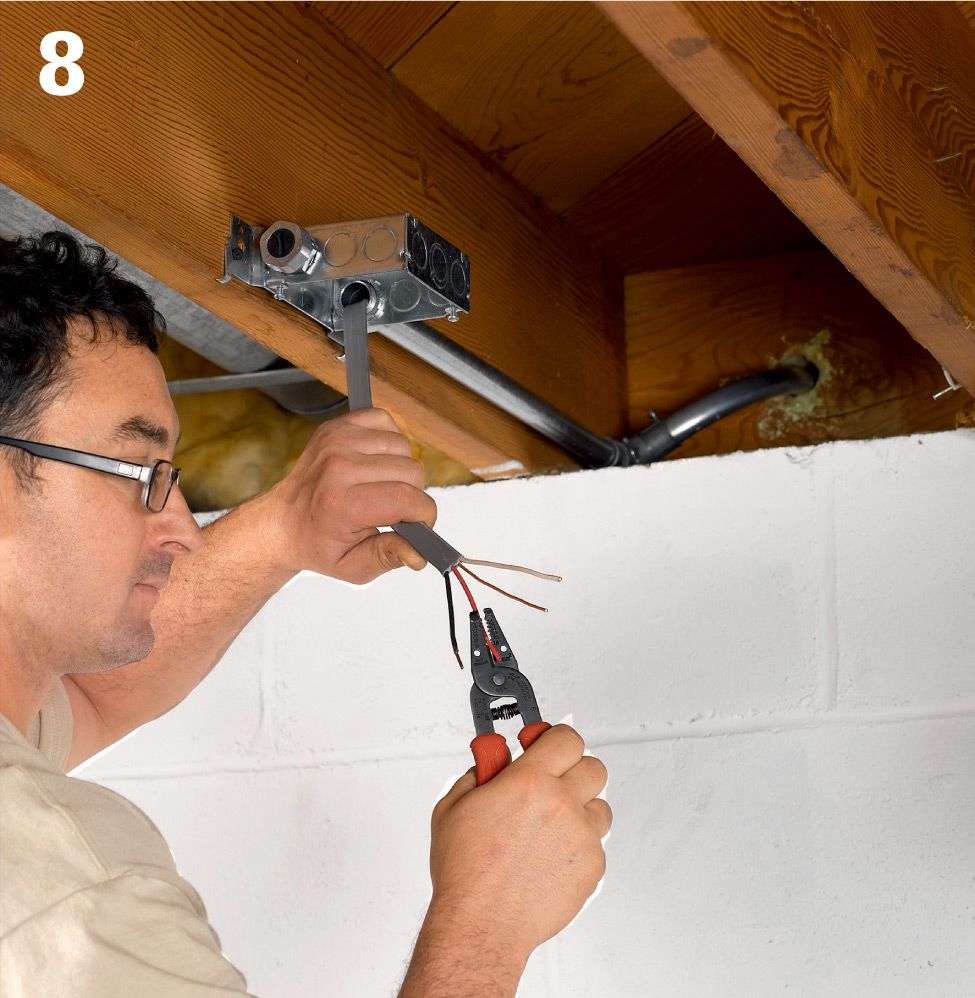
Run UF cable from the house to the outbuilding. Feed one end of the UF circuit cable up through the sweep and conduit and into the L-fitting at the house (the back or side of the fitting is removable to facilitate cabling). Run the cable through the wall and into the junction box, leaving at least 12" of extra cable at the end.
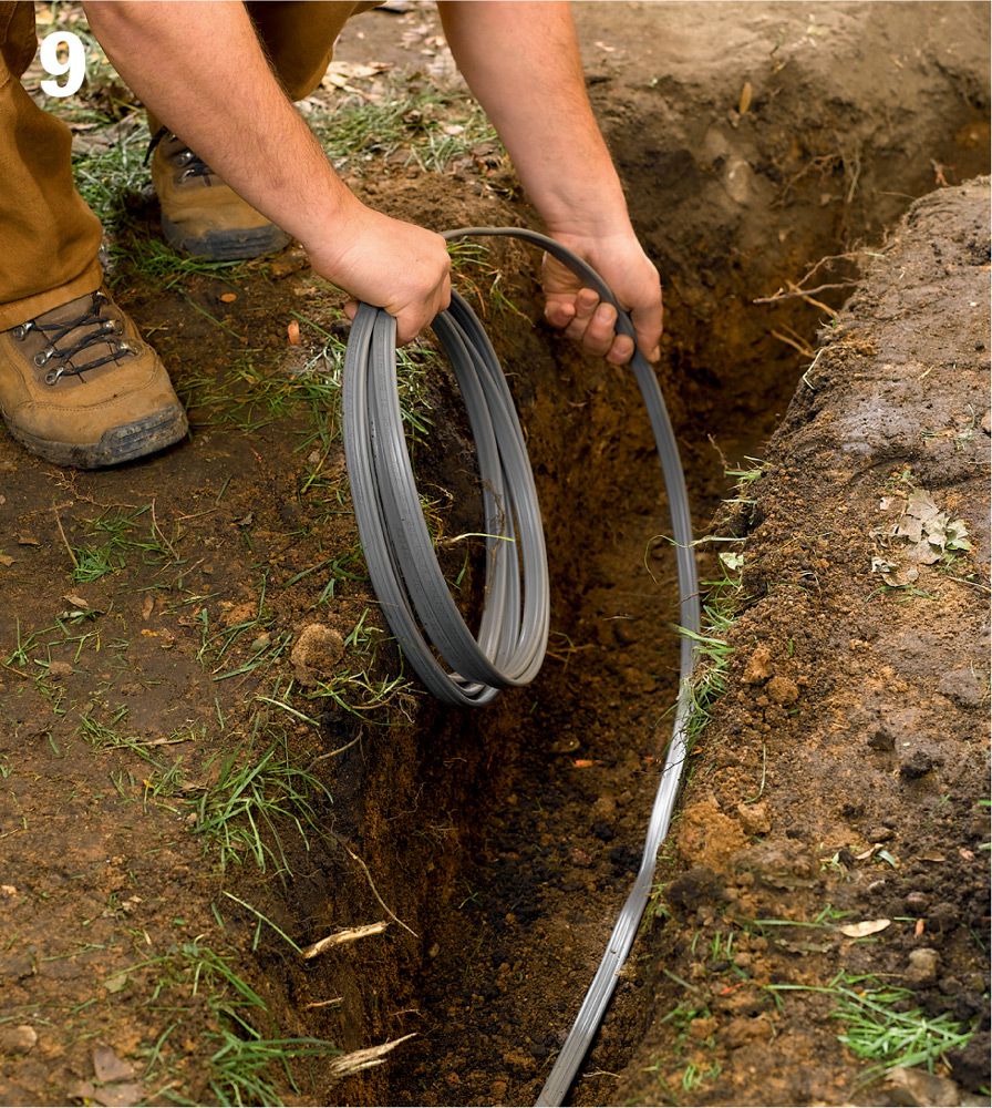
Lay the UF cable into the trench, making sure it is not twisted and will not contact any sharp objects. Roll out the cable, and then feed the other end of the cable up through the conduit and into the receptacle box in the shed, leaving 12" of slack.
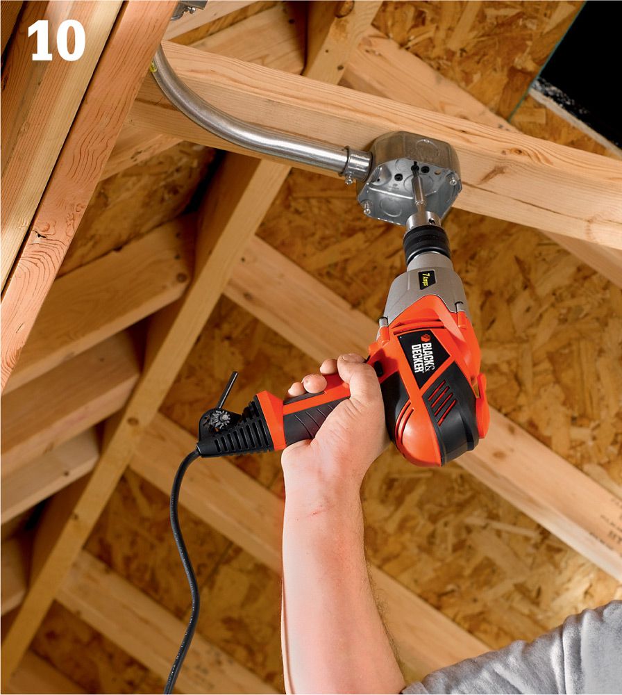
Inside the outbuilding, install the remaining boxes for the other switches, receptacles, and lights. With the exception of plastic receptacle boxes for exterior exposure, use metal boxes if you will be connecting the boxes with metal conduit.
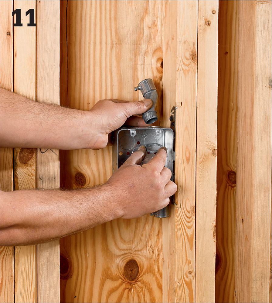
Connect the electrical boxes with conduit and fittings. Inside the outbuilding, you may use inexpensive EMT to connect receptacle, switch, and fixture boxes. Once you’ve planned your circuit routes, start by attaching couplings to all of the boxes.
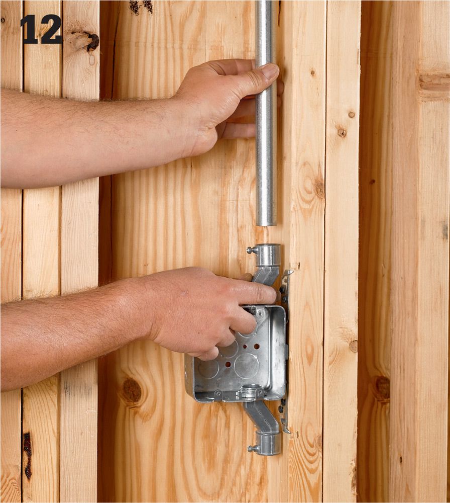
Cut a length of conduit to fit between the coupling and the next box or fitting in the run. If necessary, drill holes for the conduit through the centers of the wall studs. Attach the conduit to the fitting that you attached to the first box.
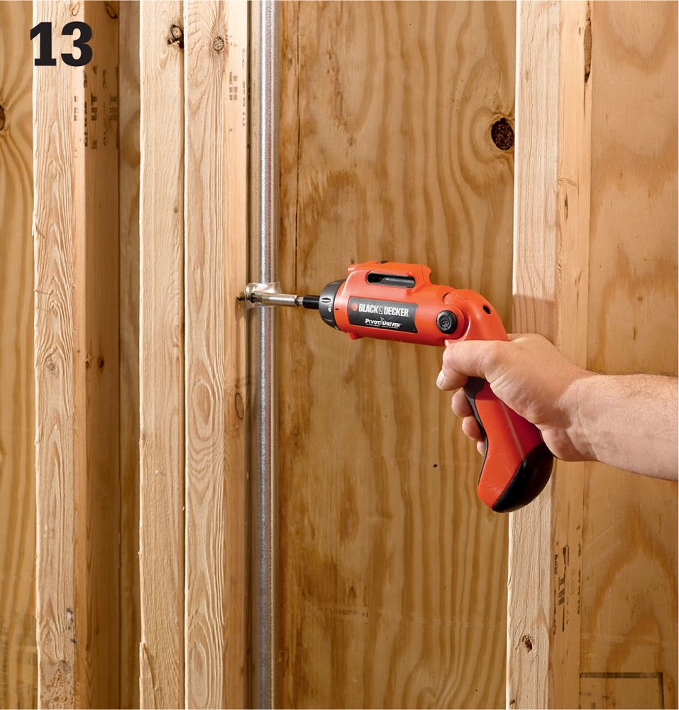
If you are surface-mounting the conduit or running it up or down next to wall studs, secure it with straps no more than 3 ft. apart. Use elbow fittings for 90° turns and setscrew couplings for joining straight lengths as needed. Make holes through the wall studs only as large as necessary to feed the conduit through.
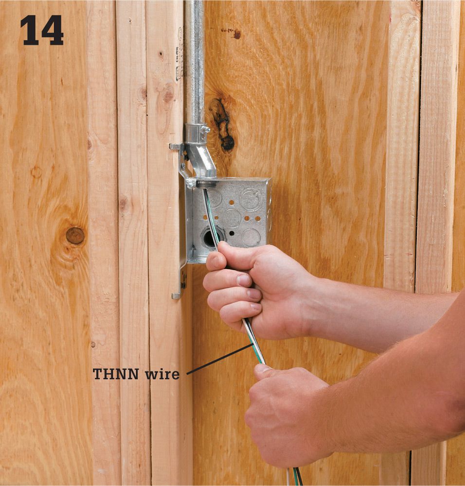
Measure to find how much wire you’ll need for each run, and cut pieces that are a foot or two longer. Before making L-turns with the conduit, feed the wire through the first conduit run.
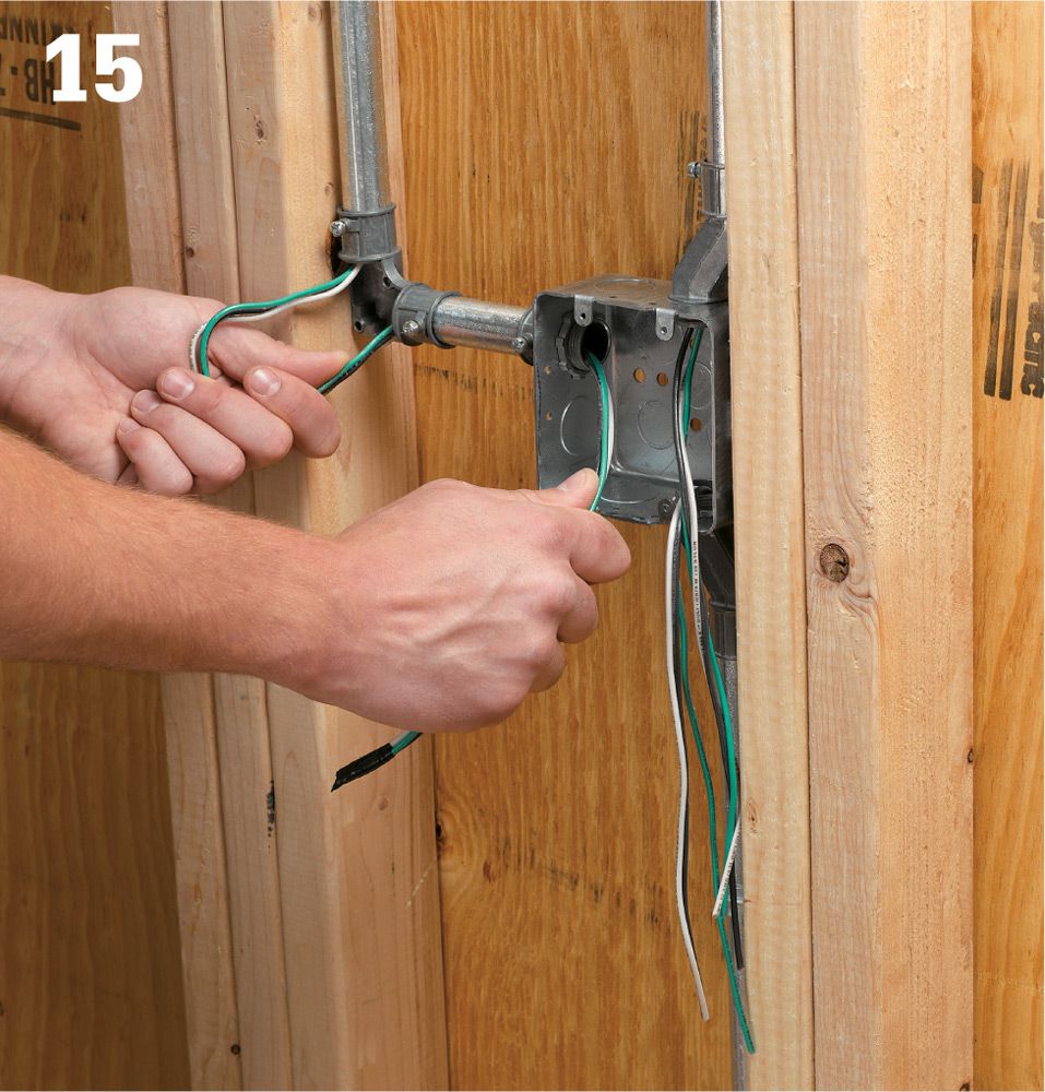
Feed the other ends of the wires into the next box or fitting in line. It is much easier to feed wire into 45° and 90° elbows if they have not been attached to the conduit yet. Continue feeding wire into the conduit and fitting until you have reached the next box in line.
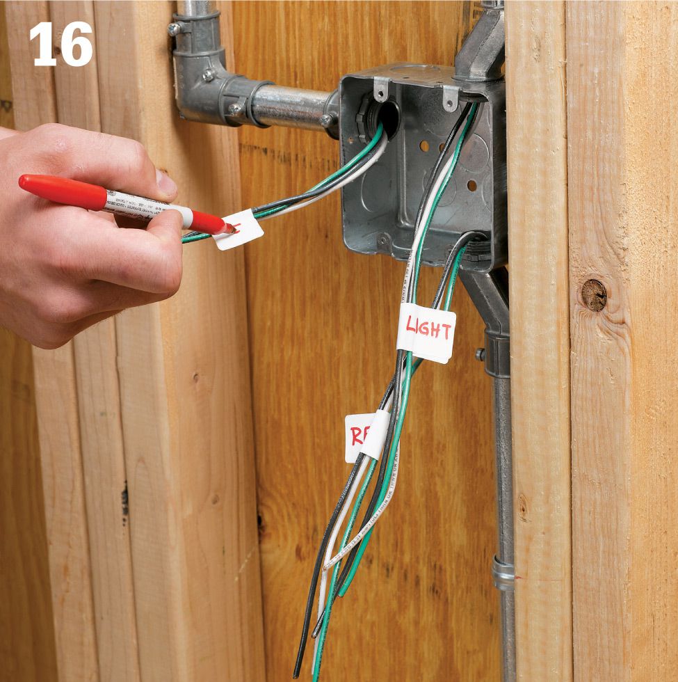
Once you’ve reached the next box in line, coil the ends of the wires and repeat the process with new wire for the next run. Keep working until all of the wire is run and all of the conduit and fittings are installed and secured. If you are running multiple feed wires into a single box, write the origin or destination on a piece of masking tape and stick it to each wire end.
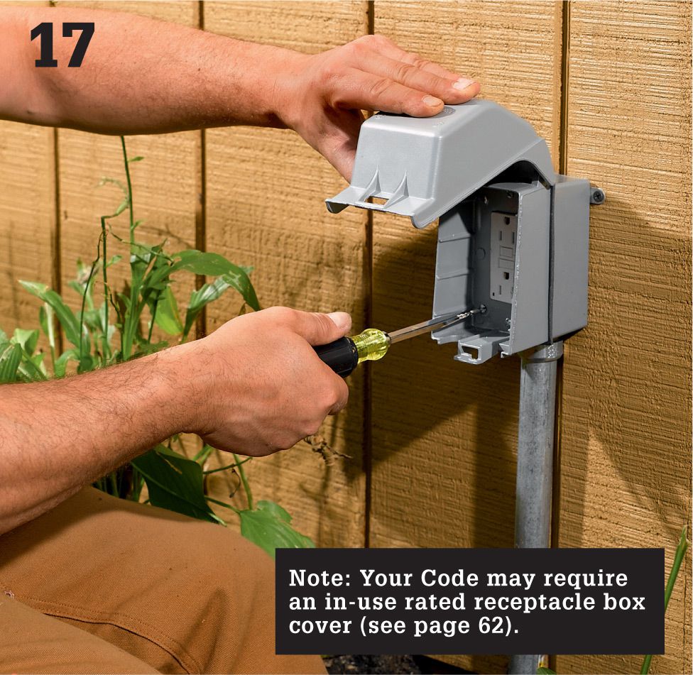
Make the wiring connections at the receptacles. Strip 3/4" of insulation from the circuit wires using a wire stripper. Connect the white (neutral) wire and black (hot) wire of the UF cable to the LINE screw terminals on the receptacle. Connect the white (neutral) and black (hot) wires from the NM cable to the LOAD terminals. Pigtail the bare copper ground wires and connect them to the receptacle ground terminal and the metal box. Install the receptacle and cover plate.
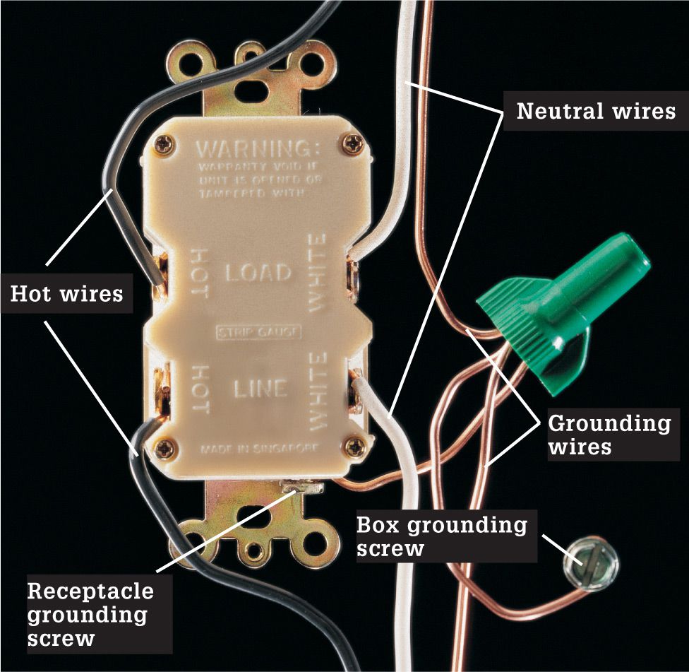
Variation: Installing a GFCI-protected breaker for the new circuit at the main service panel is the best way to protect the circuit and allows you to use regular receptacles in the building, but an alternative that is allowed in many areas is to run the service into a GFCI-protected receptacle and then wire the other devices on the circuit in series. If you use this approach, only the initial receptacle needs to be a GFCI receptacle.
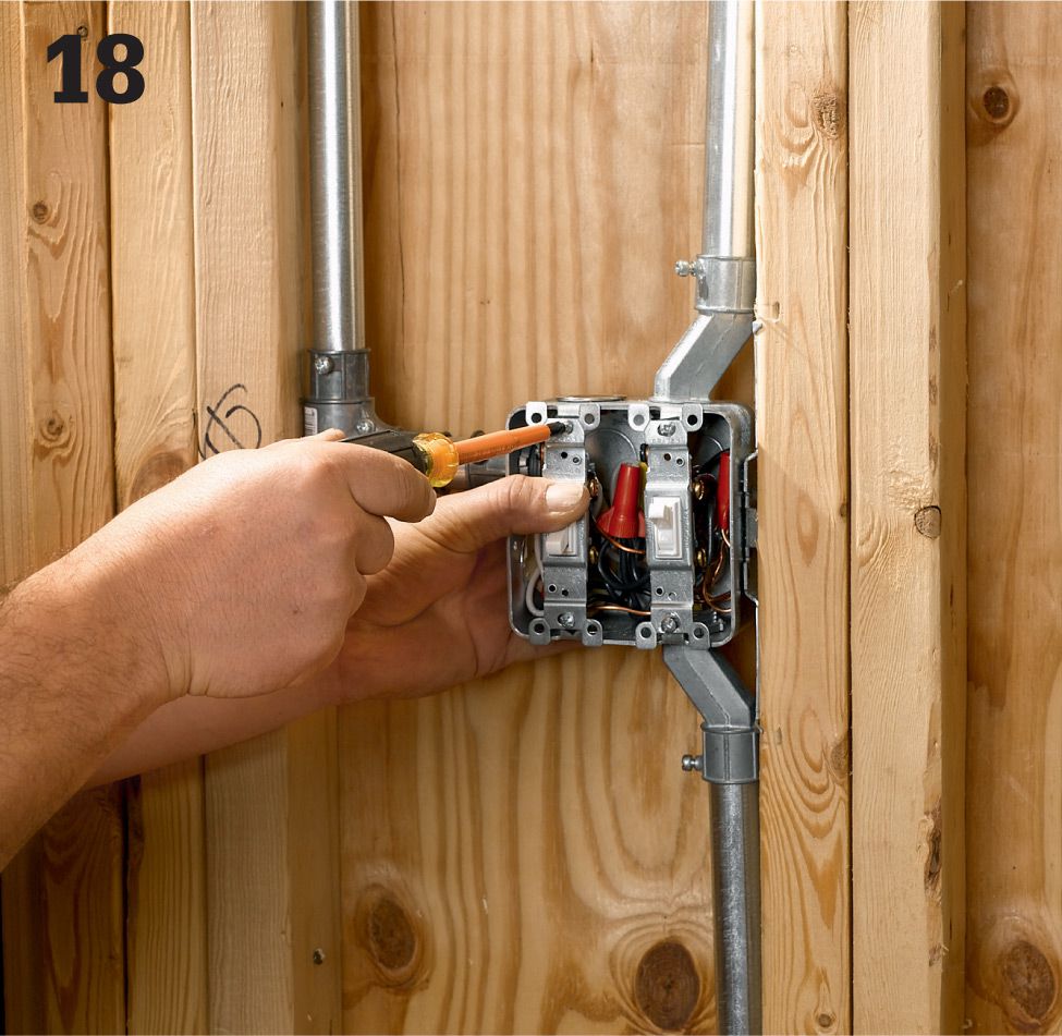
Continue installing receptacles in the circuit run, and then run service from the last receptacle to the switch box for the light fixture or fixtures. (If you anticipate a lot of load on the circuit, you should probably run a separate circuit for the lights). Twist the white neutral leads and grounding leads together and cap them. Attach the black wires to the appropriate switches. Install the switches and cover plate.
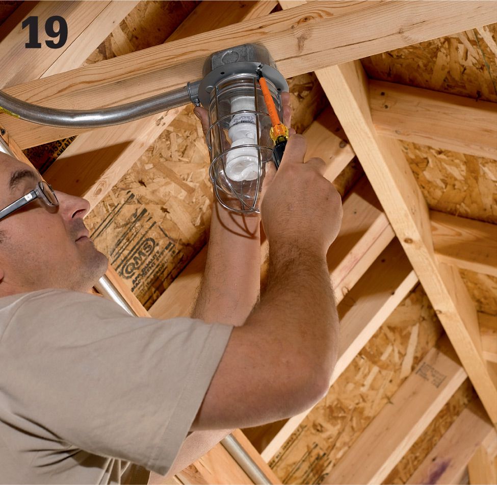
Install the light fixtures. For this shed, we installed a caged ceiling light inside the shed and a motion-detector security light on the exterior side (see pages 280 to 283).
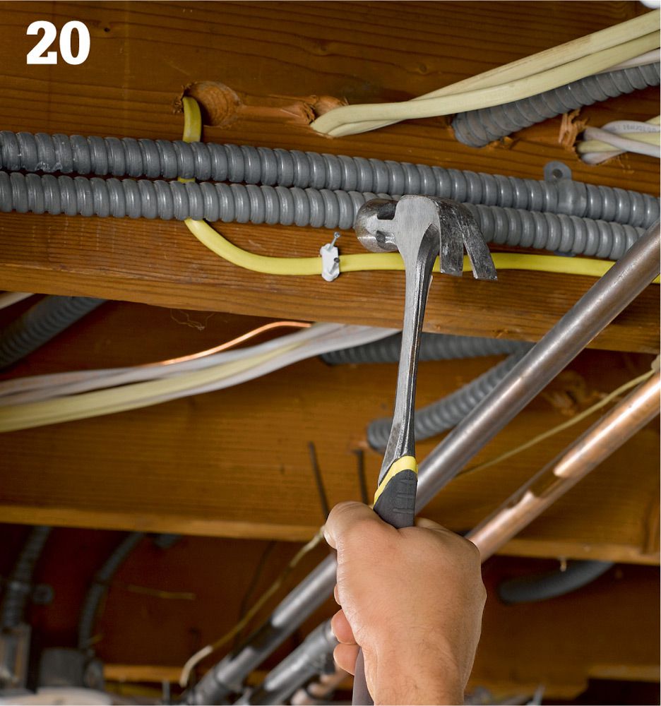
Run NM cable from the electrical box in the house at the start of the new circuit to the main service panel. Use cable staples if you are running the cable in floor joist cavities. If the cable is mounted to the bottom of the floor joists or will be exposed, run it through conduit.
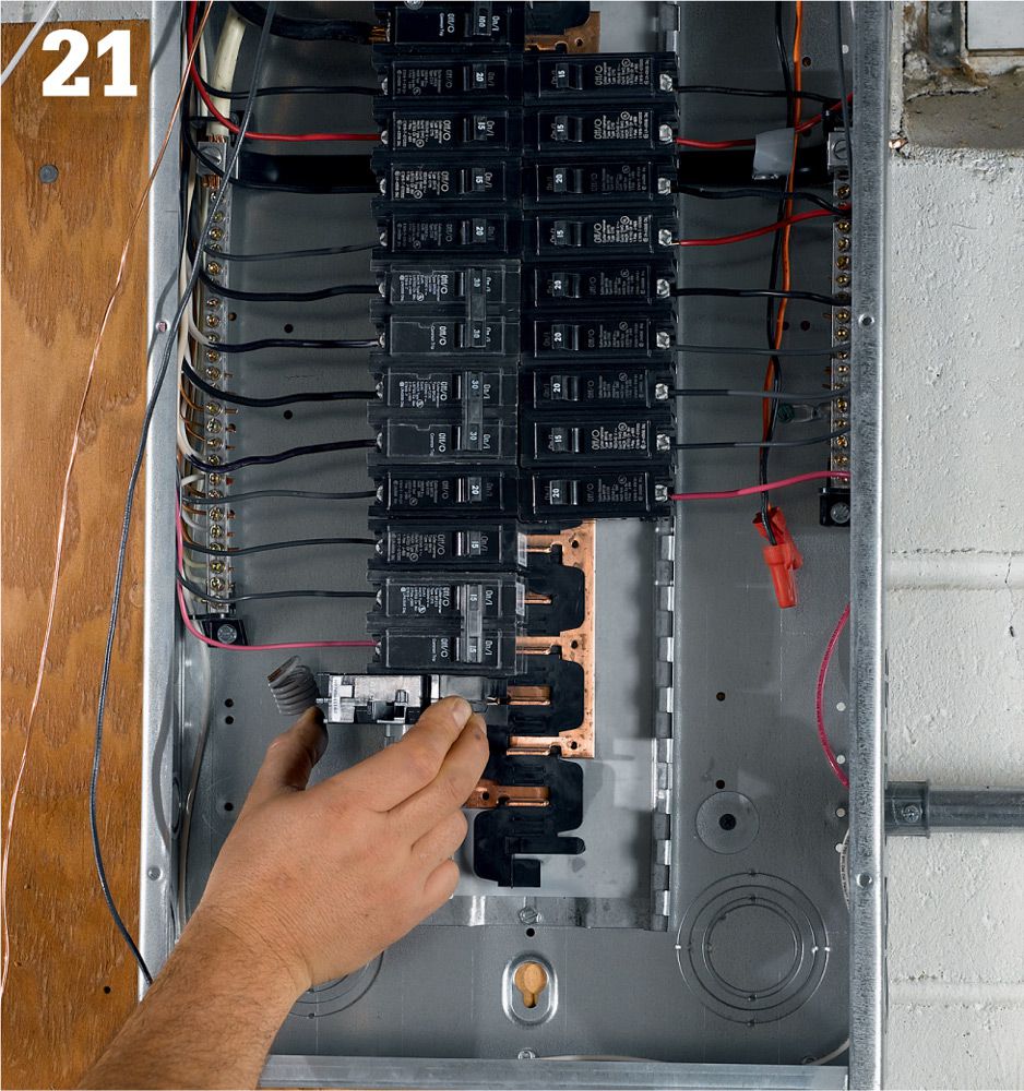
At the service panel, feed the NM cable in through a cable clamp. Arrange for your final electrical inspection before you install the breaker. Then attach the wires to a new circuit breaker, and install the breaker in an empty slot. Label the new circuit on the circuit map.
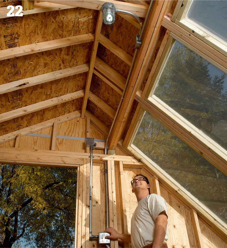
Turn on the new circuit, and test all of the receptacles and fixtures. Depress the Test button and then the Reset button if you installed a GFCI receptacle. If any of the fixtures or receptacles is not getting power, check the connections first, and then test the receptacle or switch for continuity with a multimeter. Backfill the trench.
![]() Motion-Sensing Floodlights
Motion-Sensing Floodlights
Most houses and garages have floodlights on their exteriors. You can easily upgrade these fixtures so that they provide additional security by replacing them with motion-sensing floodlights. Motion-sensing floods can be set up to detect motion in a specific area—like a walkway or driveway—and then cast light into that area. And there are few things intruders like less than the spotlight. These lights typically have timers that allow you to control how long the light stays on and photosensors that prevent the light from coming on during the day.
Tools & Materials ![]()
Circuit tester
Jigsaw
Fish tape
Screwdrivers
Wire cutter
Cable ripper
Wire stripper
Caulk gun
Motion-sensing floodlight fixture
Electrical box
NM cable
Wire connectors
Eye Protection
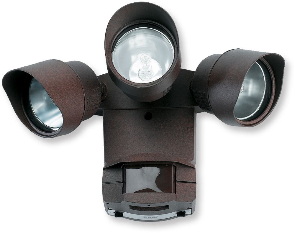
A motion-sensing light fixture provides inexpensive and effective protection against intruders. It has an infrared eye that triggers the light fixture when a moving object crosses its path. Choose a light fixture with a photo cell to prevent the light from turning on in daylight; an adjustable timer to control how long the light stays on; and range control to adjust the reach of the motion-sensor eye.
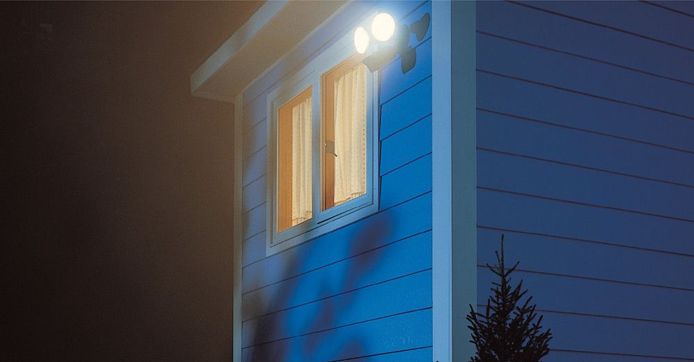
An exterior floodlight with a motion sensor is an effective security measure. Keep the motion sensor adjusted to cover only the area you wish to secure—if the coverage area is too large, the light will turn on frequently.
![]() How to Install a New Exterior Fixture Box
How to Install a New Exterior Fixture Box
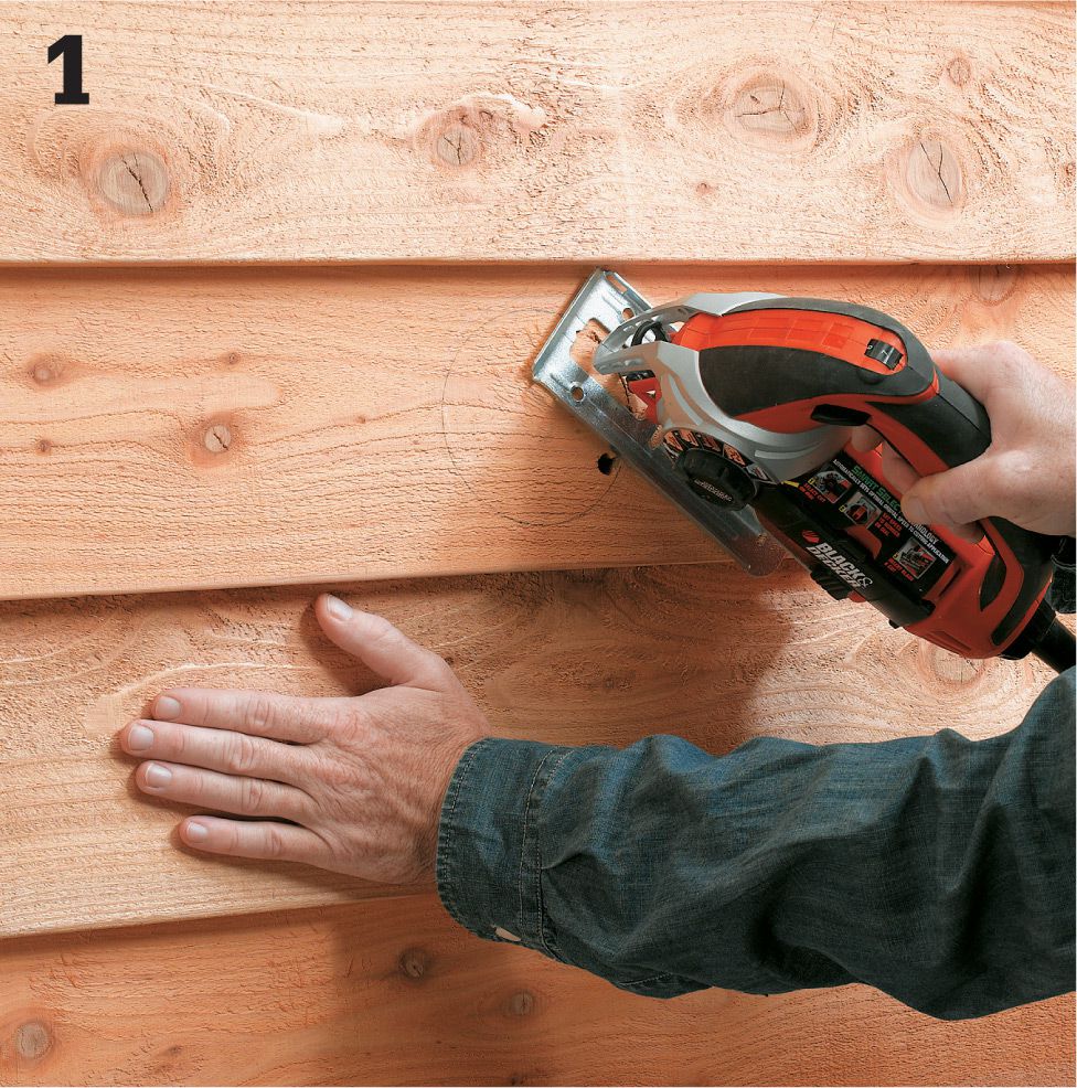
On the outside of the house, make the cutout for the motion-sensor light fixture. Outline the light fixture box on the wall, drill a pilot hole, and complete the cutout with a wallboard saw or jigsaw.
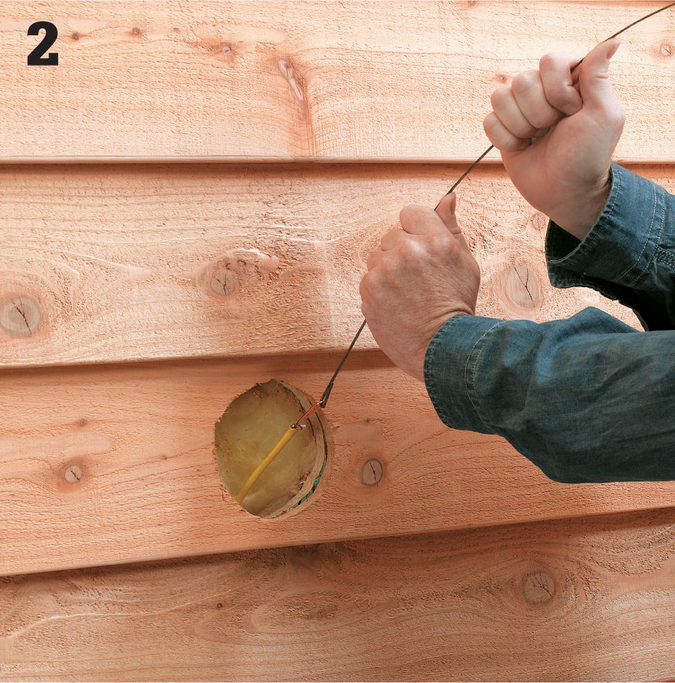
Estimate the distance between the indoor switch box and the outdoor motion-sensor box, and cut a length of NM cable about 2 ft. longer than this distance. Use a fish tape to pull the cable from the switch box to the motion-sensor box. See pages 41 and 42 for tips on running cable through finished walls.
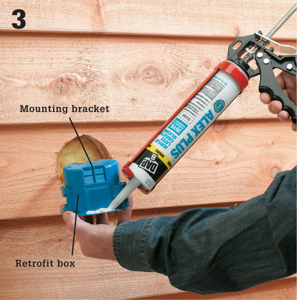
Strip about 10" of outer insulation from the end of the cable using a cable ripper. Open a knockout in the retrofit light fixture box with a screwdriver. Insert the cable into the box so that at least 1/4" of outer sheathing reaches into the box. Apply a heavy bead of silicone or polyurethane caulk to the flange of the electrical box before attaching it to the wall.
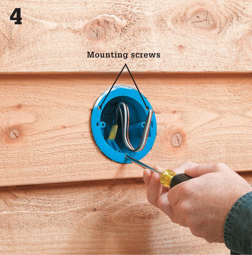
Insert the box into the cutout opening, and tighten the mounting screws until the brackets draw the outside flange firmly against the siding.
![]() How to Replace a Floodlight with a Motion-Sensor Light
How to Replace a Floodlight with a Motion-Sensor Light
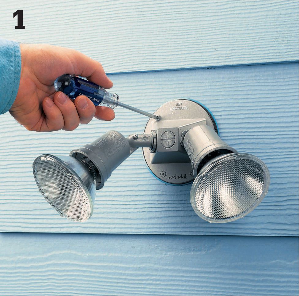
Turn off power to the old fixture. To remove it, unscrew the mounting screws on the part of the fixture attached to the wall. There will probably be four of them. Carefully pull the fixture away from the wall, exposing the wires. Don’t touch the wires yet.
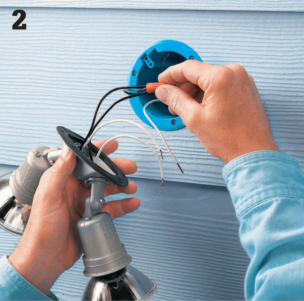
Before you touch any wires, use a voltage sensor to verify that the circuit is dead. With the light switch turned on, insert the sensor’s probe into the electrical box and hold the probe within 1/2" of the wires inside to confirm that there is no voltage. Disconnect the wire connectors, and remove the old fixture.
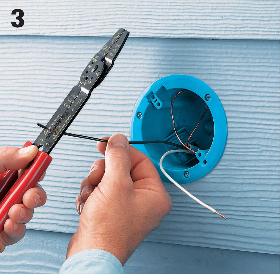
Examine the ends of the three wires coming from the box (one white, one black, and one bare copper). They should be clean and free of corrosion. If the ends are in poor condition, clip them off and then strip 3/4" of wire insulation with a combination tool.
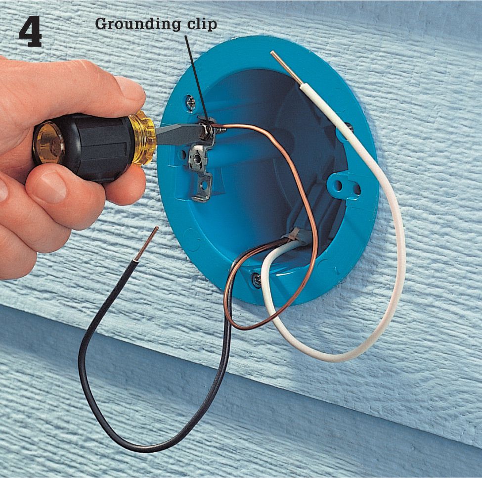
If the electrical box is nonmetallic and does not have a metal grounding clip, install a grounding clip or replace the box with one that does have a clip, and make sure the ground wire is attached to it securely. Some light fixtures have a grounding terminal on the base. If yours has one, attach the grounding wire from the house directly to the terminal.
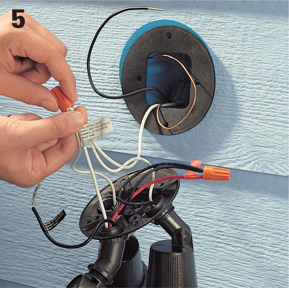
Now you can attach the new fixture. Begin by sliding a rubber or foam gasket (usually provided with the fixture) over the wires and onto the flange of the electrical box. Set the new fixture on top of a ladder or have a helper hold it while you make the wiring connections. There may be as many as three white wires coming from the fixture. Join all white wires, including the feed wire from the house, using a wire connector.
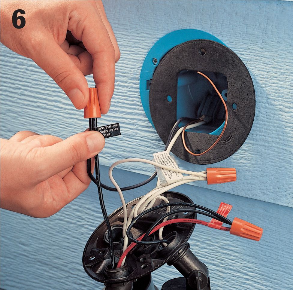
Next, join the black wire from the box and the single black wire from the fixture with a wire connector. You may see a couple of black wires and a red wire already joined on the fixture. You can ignore these in your installation.
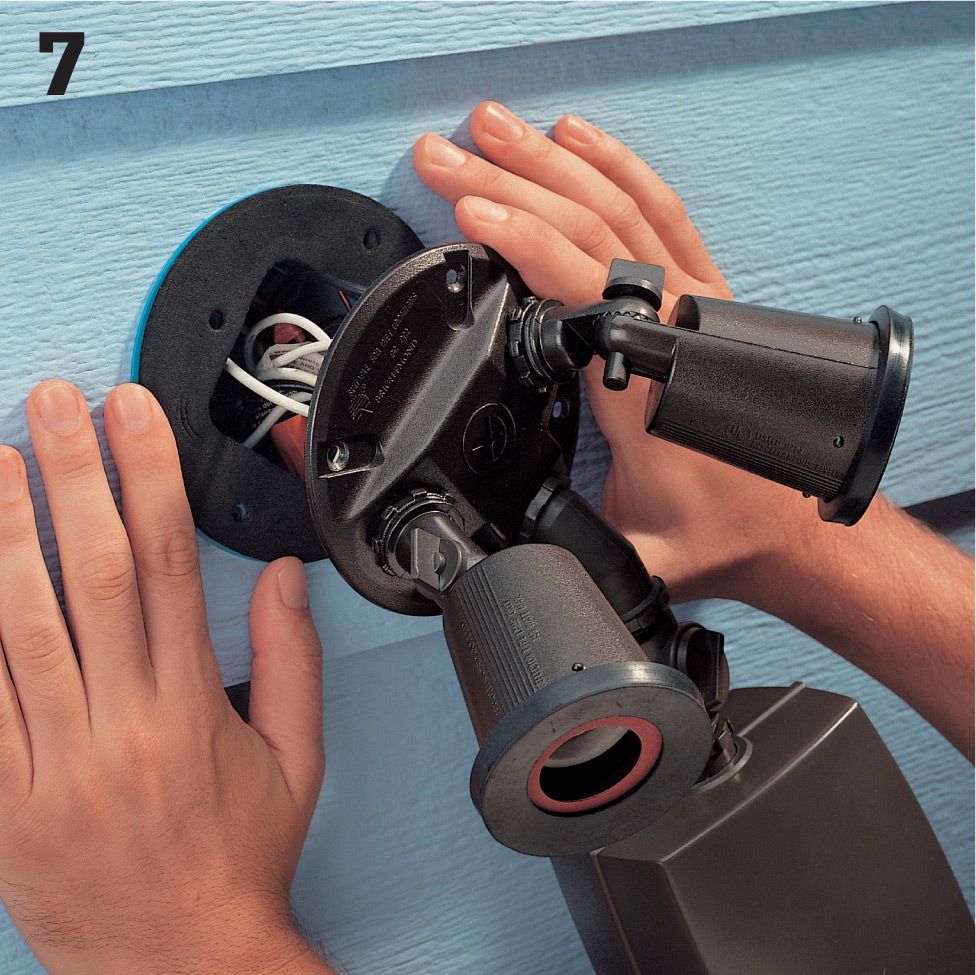
Neatly tuck all the wires into the box so they are behind the gasket. Align the holes in the gasket with the holes in the box, and then position the fixture over the gasket so its mounting holes are also aligned with the gasket. Press the fixture against the gasket, and drive the four mounting screws into the box. Install floodlights (exterior rated) and restore power.
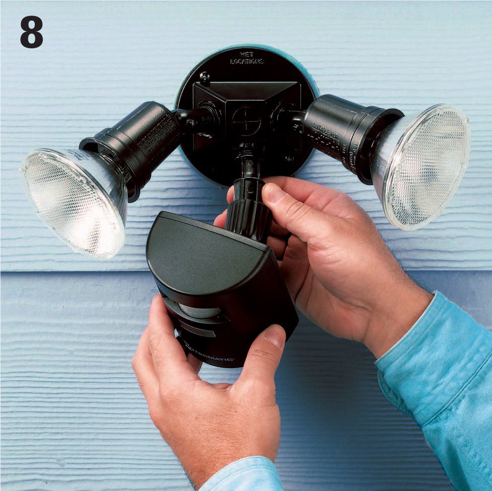
Test the fixture. You will still be able to turn it on and off with the light switch inside. Flip the switch on and pass your hand in front of the motion sensor. The light should come on. Adjust the motion sensor to cover the traffic areas, and pivot the light head to illuminate the intended area.
![]() Standalone Solar Lighting System
Standalone Solar Lighting System
Aself-contained electrical circuit with dedicated loads, usually 12-volt light fixtures, is one of the most useful solar amenities you can install. A standalone system is not tied into your power grid, which greatly reduces the danger of installing the components yourself. Plus, the fact that your light fixtures are independent of the main power source means that even during a power outage you will have functioning emergency and security lights.
Installing a single solar-powered circuit is relatively simple, but don’t take the dangers for granted. Your work will require permits and inspections in most jurisdictions, and you can’t expect to pass if the work is not done to the exact specifications required.
Solar panels that convert the sun’s energy into electricity are called photovoltaic (PV) panels, and they produce direct current (DC) power. PV solar panel systems can be small and designed to accomplish a specific task, or they can be large enough to provide power or supplementary power to an entire house. Before you make the leap into a large system, it’s a good idea to familiarize yourself with the mechanics of solar power. The small system demonstrated in this project is relatively simple and is a great first step into the world of solar. The fact that the collector, battery, and lights are a standalone system makes this a very easy project to accomplish. By contrast, installing panels that provide direct supplementary power through your main electrical service panel is a difficult wiring job that should be done by professional electricians only.
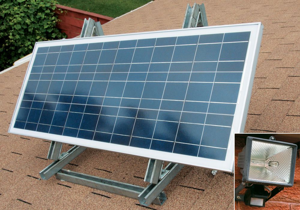
This 60-watt solar panel is mounted on a garage roof and powers a self-contained home security lighting system. Not only does this save energy costs, it keeps the security lights working even during power outages.
![]() Schematic Diagram for an Off-the-Grid Solar Lighting System
Schematic Diagram for an Off-the-Grid Solar Lighting System
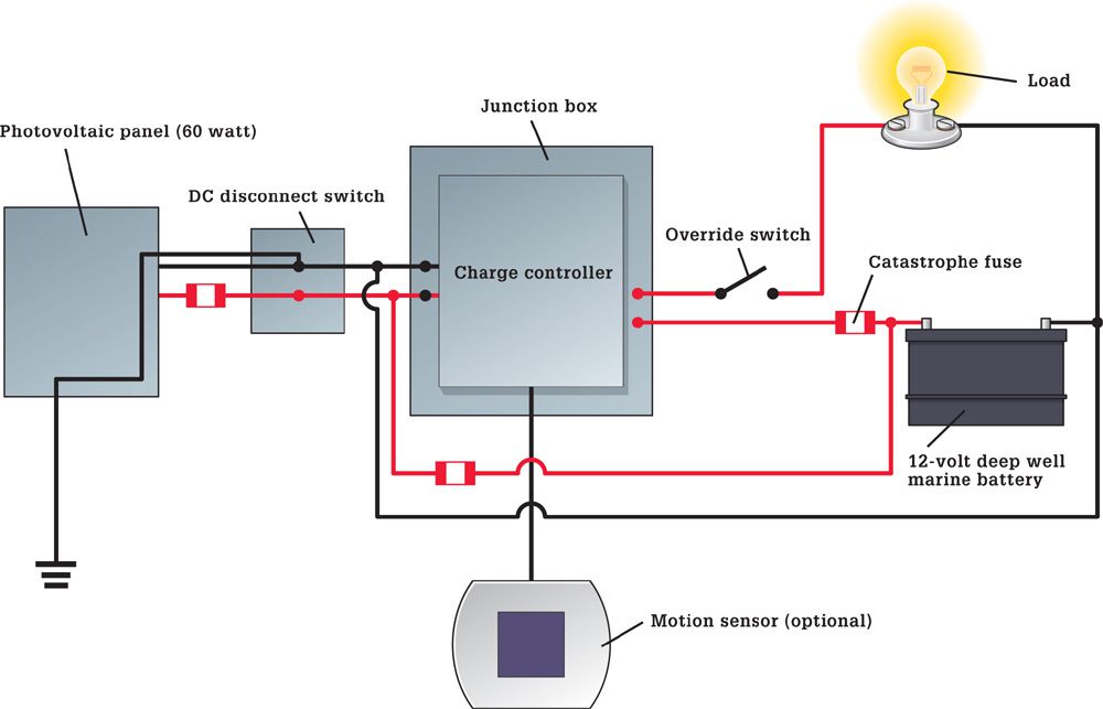
Tools & Materials ![]()
Tape measure
Drill/driver with bits
Caulk gun
Crimping tool
Wiring tools
Metal-cutting saw
Photovoltaic panel (50 to 80 watts)
Charge controller
Catastrophe fuse
Battery sized for 3 day autonomy
Battery case
Battery cables
12-volt LED lights including motion-sensor light
Additional 12-volt light fixtures as desired
20 ft. Unistrut 1 7/8" thick U-channel (See Resources, page 331)
(4) 45° Unistrut connectors
(2) 90° Unistrut angle brackets
(4) Unistrut hold down clamps
(12) 3/8" spring nuts
(12) 3/8"-dia. × 1"-long hex-head bolts with washers
DC-rated disconnect or double throw snap switch
6" length of 1/2"-dia. liquid-tight flexible metallic conduit
(2) 1/2" liquid tight connectors
(2) Lay-in grounding lugs
(2) Insulated terminal bars to accept one 2-gauge wire and 4 12-gauge wires
(2) Cord cap connectors for 1/2"-dia. cable
1/2" ground rod and clamp
Copper wire (6, 12-gauge)
Green ground screws
1/2" Flexible metallic conduit or Greenfield
1/2" Greenfield connectors
(4) 11/16" junction boxes with covers
(4) square boxes with covers
PVC 6"× 6" junction box with cover
14/2 UF wire
1/4" × 20 nuts and bolts with lock washers
Roof flashing boot
Roof cement
Silicon caulk
Eye protection
![]() Mounting PV Panels
Mounting PV Panels
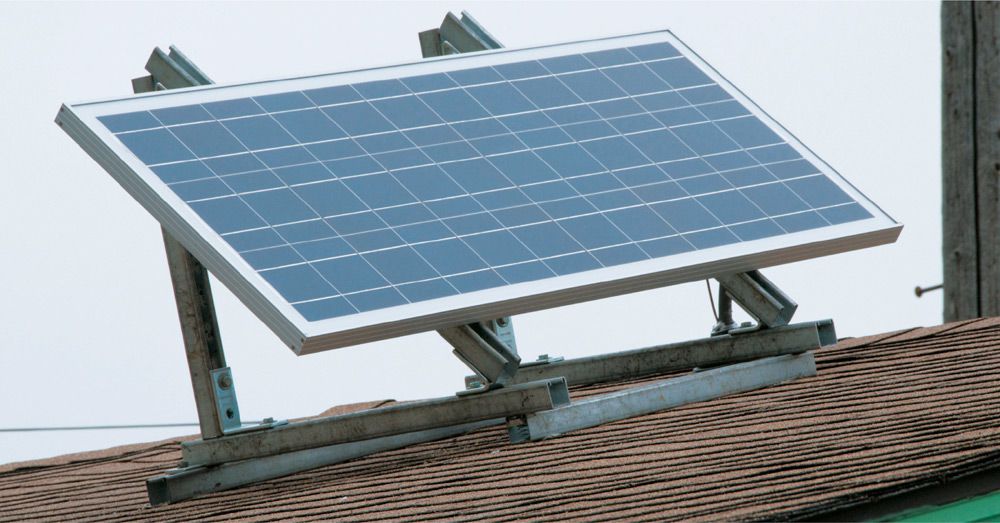
The mounting stand for the PV panel is constructed from metal U-channel (a product called Unistrut is seen here. See Resources page 331) and pre-bent fasteners. Position the solar panel where it will receive the greatest amount of sunlight for the longest period of time each day—typically the south-facing side of a roof or wall. For a circuit with a battery reserve that powers two to four 12-volt lights, a collection panel rated between 40 and 80 watts of output should suffice. These panels can range from $200 to $600 in price, depending on the output and the overall quality.
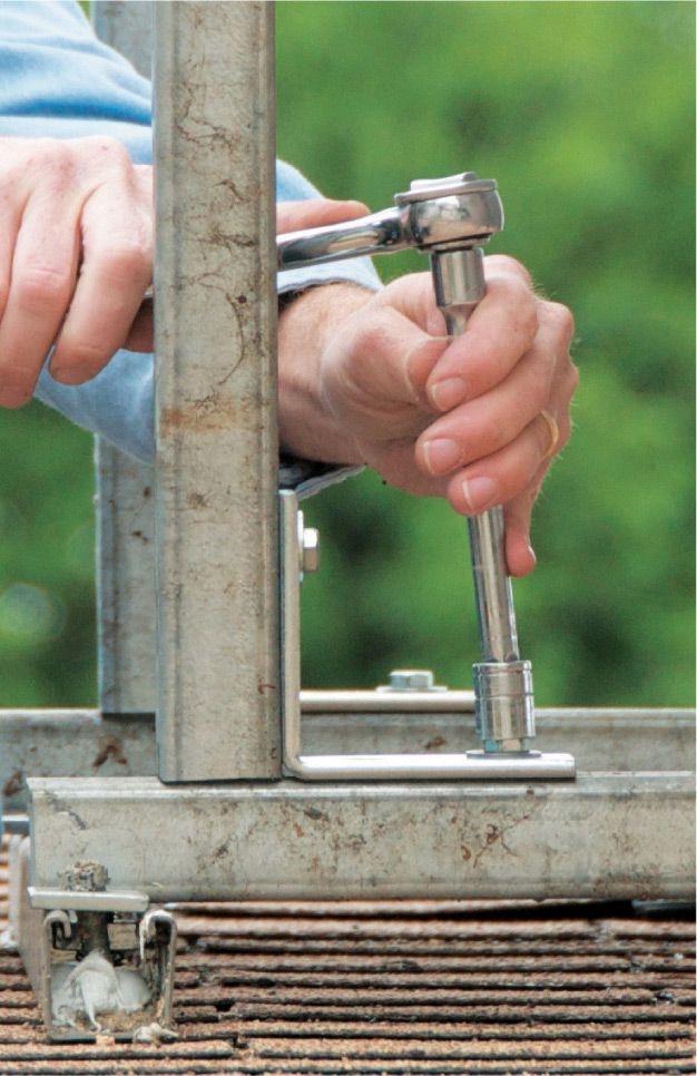
The stand components are held together with bolts and spring-loaded fasteners. The 45° and 90° connectors are manufactured specifically for use with this Unistrut system.
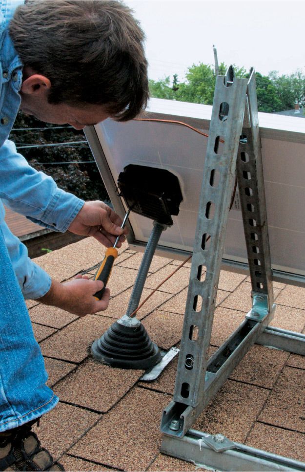
Connections for the feed wires that carry current from the collector are made inside an electrical box mounted on the back of the collector panel.
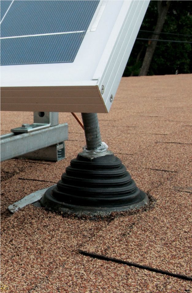
An EPDM rubber boot seals off the opening where the PVC conduit carrying the feed wires penetrates the roof.
![]() How to Wire a DC Lighting Circuit
How to Wire a DC Lighting Circuit
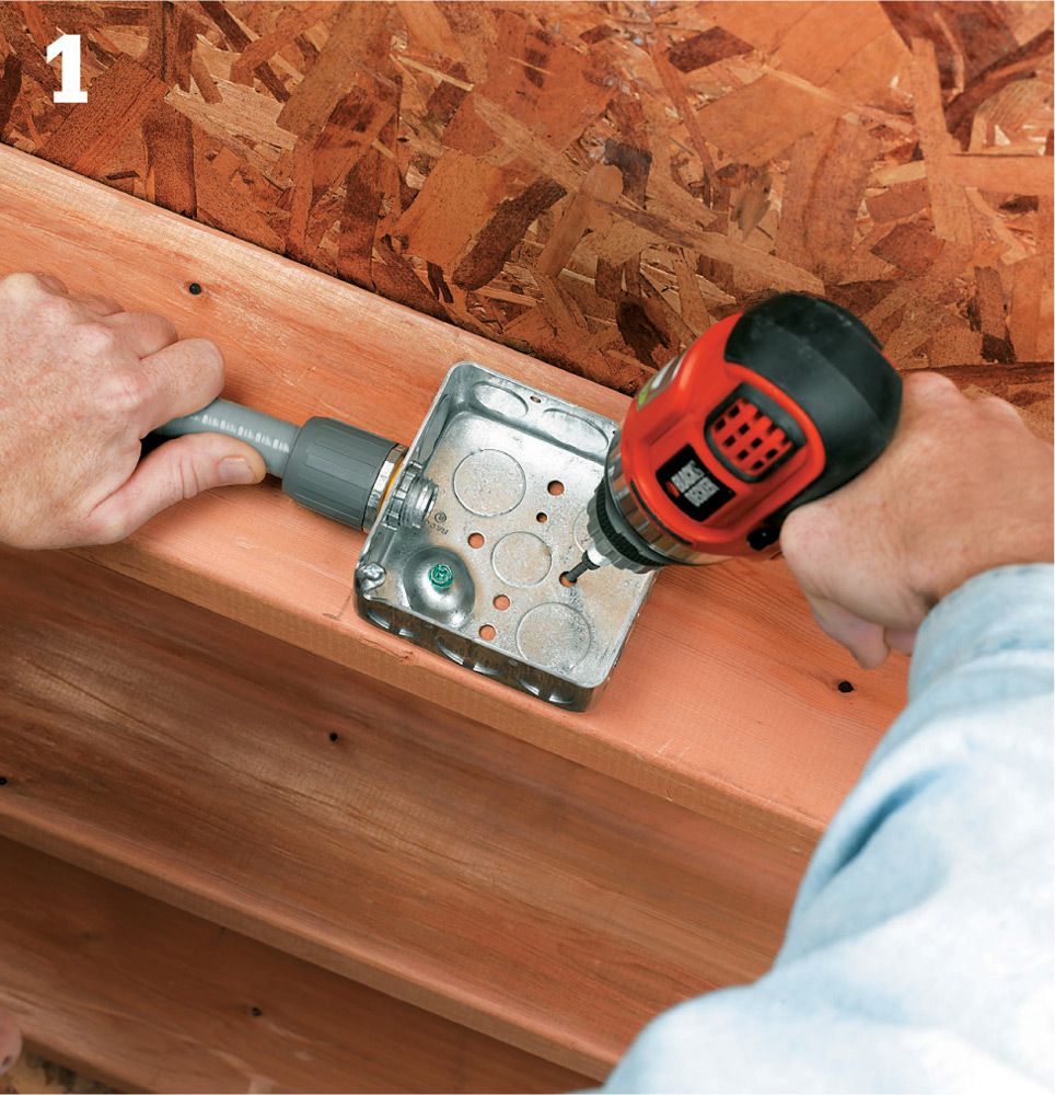
Mount a junction box inside the building where the conduit and wiring enter from the power source. Secure the box to the conduit with appropriate connectors. Run two #14 awg wires through the conduit and connect them to the positive and negative terminals on the panel (see previous page).
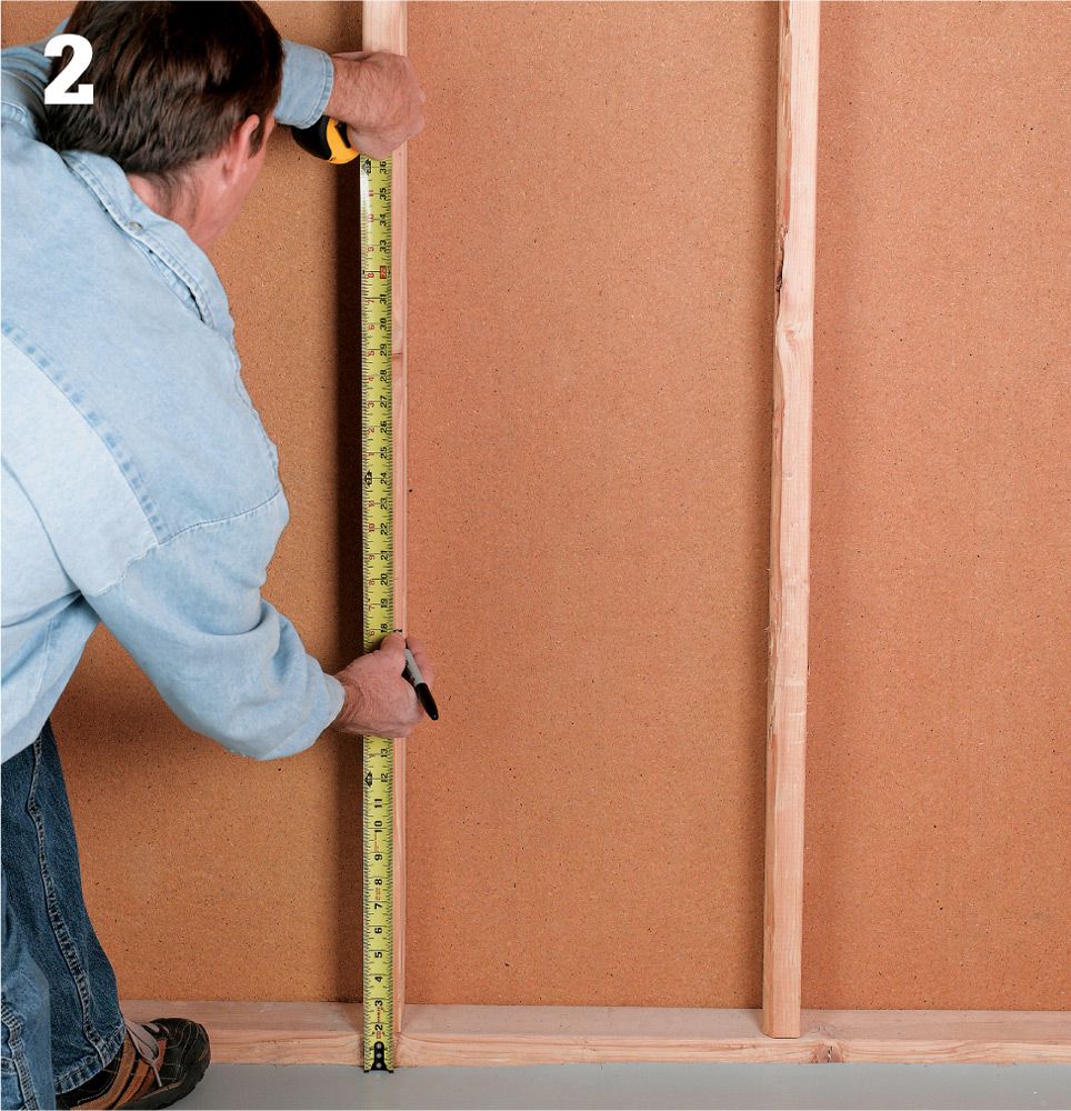
Plan the system layout. Determine the placement of the battery, and then decide where you will position the charge controller and DC disconnect. The battery should be placed at least 18" off the floor, in a well-ventilated area where it won't be agitated by everyday activity. Mark locations directly on the wall.
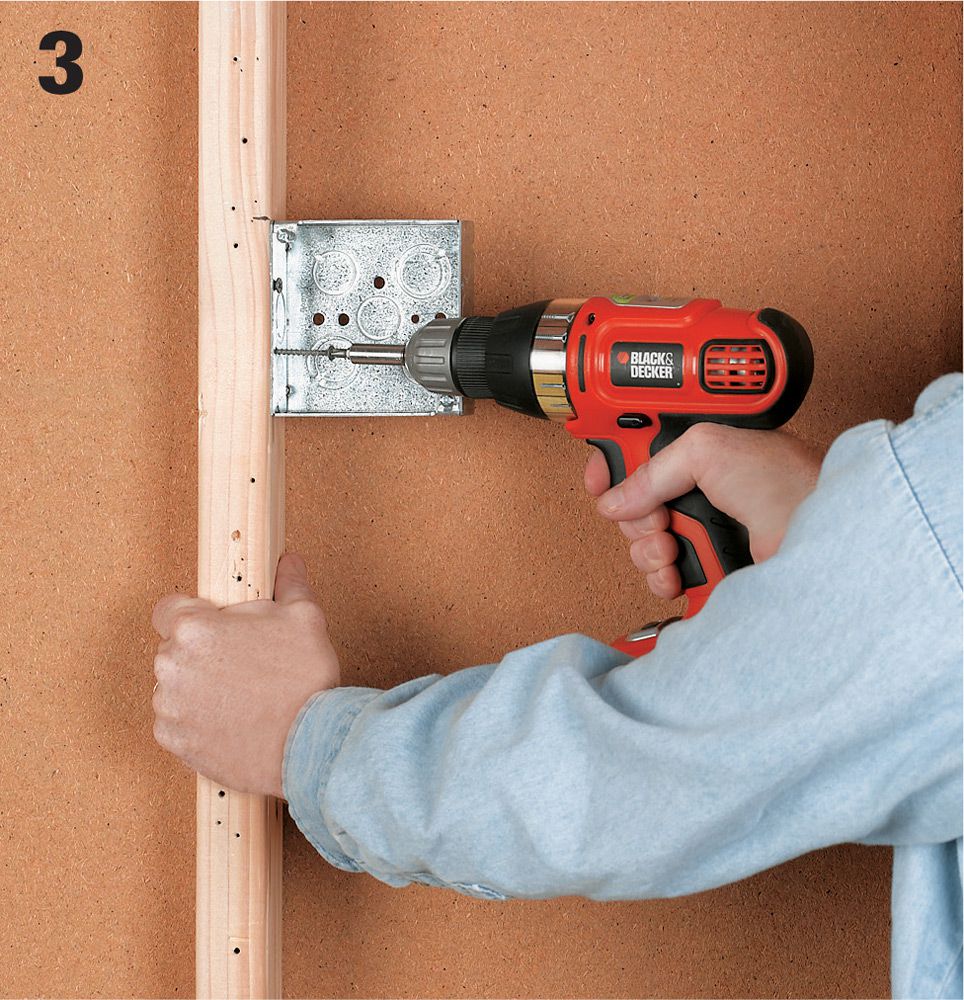
Attach a junction box for enclosing the DC disconnect, which is a heavy-duty switch, to a wall stud near the battery and charge controller location. Use a metal single-gang box with mounting flanges.
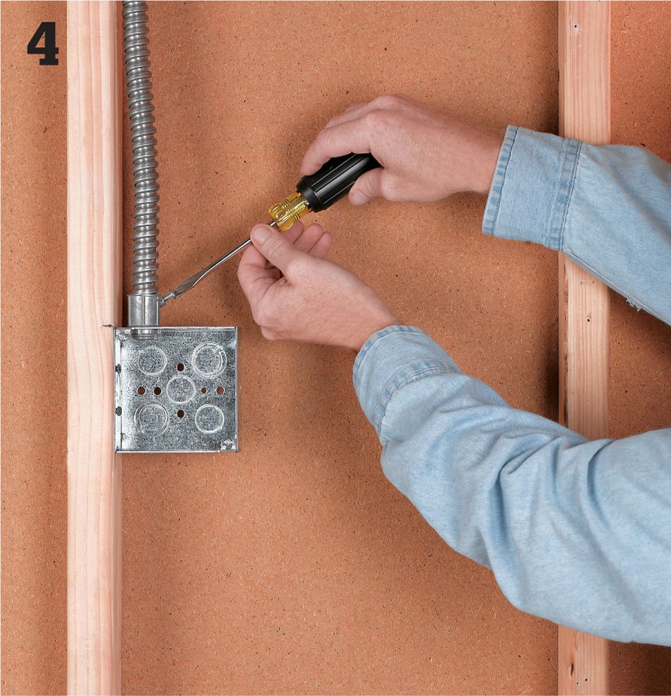
Run flexible metal conduit from the entry point at the power source to the junction box for the DC disconnect box. Use hangers rated for flexible conduit.
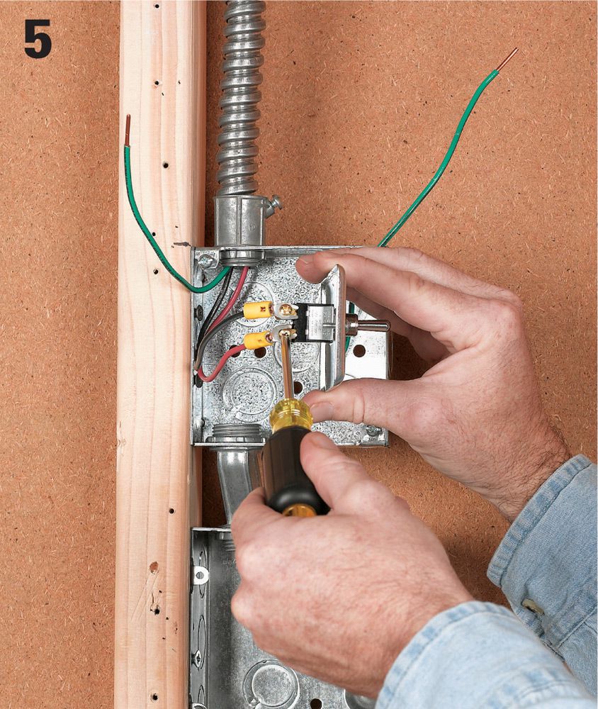
Attach the DC disconnect switch to the wire leads from the power source.
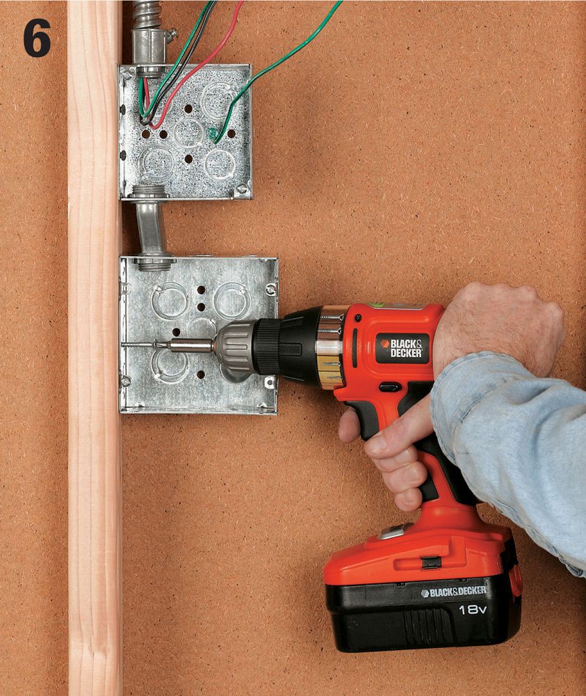
Attach a double gang metal junction box to the building's frame beneath the DC disconnect box to enclose the charge controller
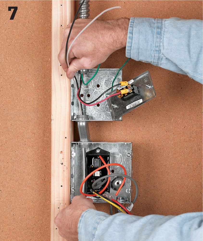
Install the charge controller inside the box. Run flexible conduit with connectors and conductors from the disconnect box and to the charge controller box.
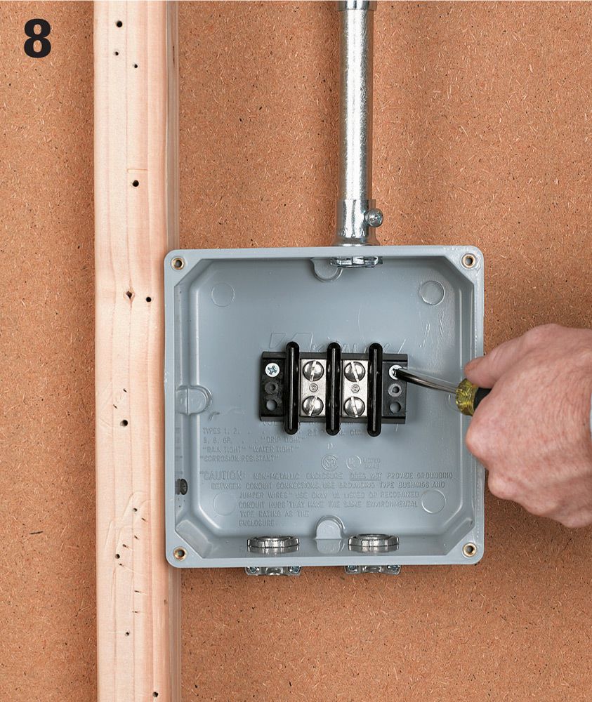
Mount a PVC junction box for the battery controller about 2 ft. above the battery location, and install two insulated terminal bars within the box.
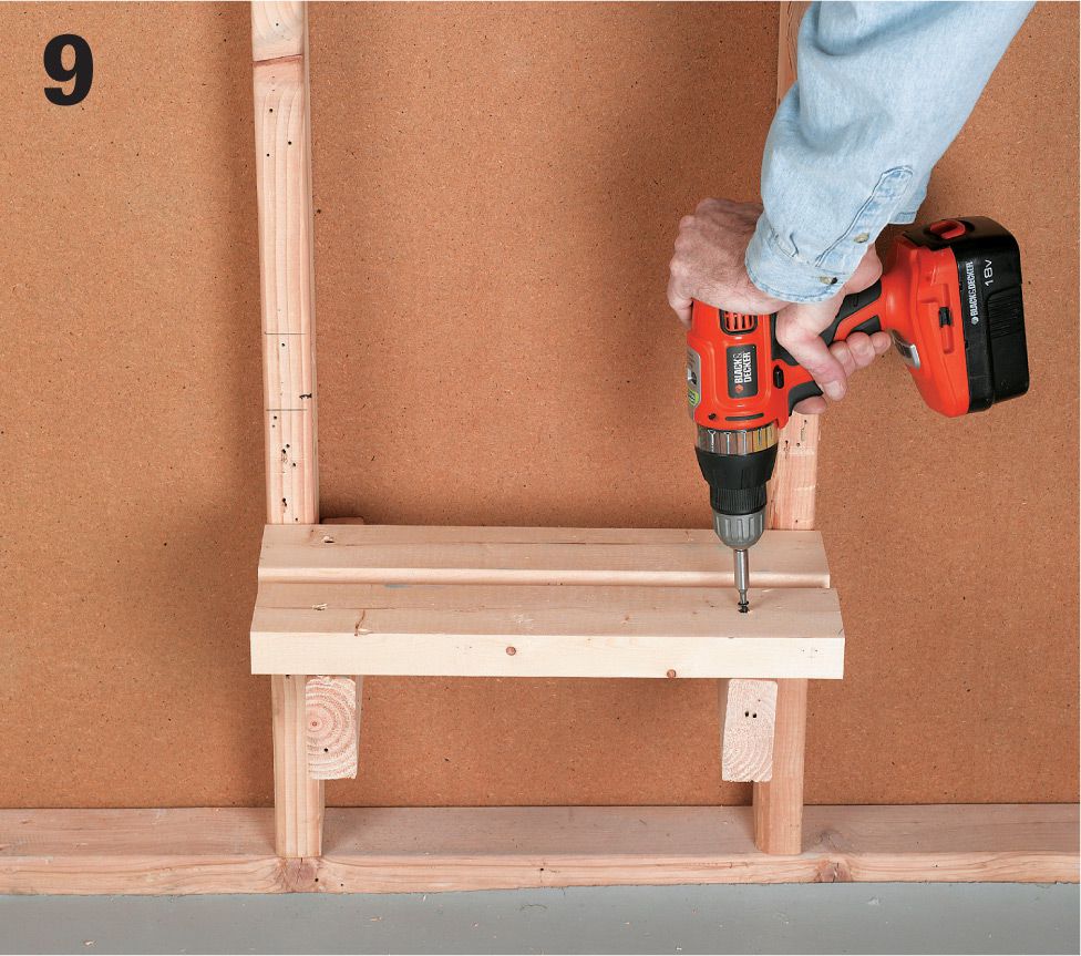
Build a support shelf for the battery using 2 x 4s. The shelf should be at least 18" above ground. Set the battery on the shelf in a sturdy plastic case.
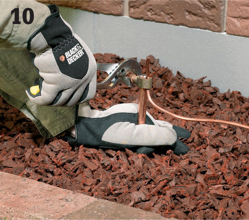
Set up grounding protection. Pound an 8-ft. long, 1/2"-dia. ground rod into the ground outside the building, about 1 ft. from the wall on the opposite side of the charge controller. Leave about 2" of the rod sticking out of the ground. Attach a ground rod clamp to the top of the rod. Drill a 5/16 hole through the garage wall (underneath a shake or siding piece) and run the #6-gauge THWN wire to the ground rod. This ground will facilitate lightning protection. See pages 180 to 185 for more information on grounding the system.
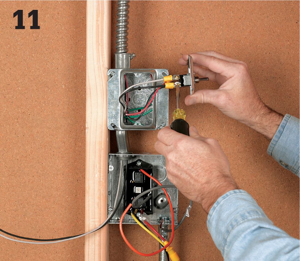
Wire the DC disconnect. Attach the two #l4-gauge wires to the two terminals labeled "line" on the top of the DC disconnect switch.
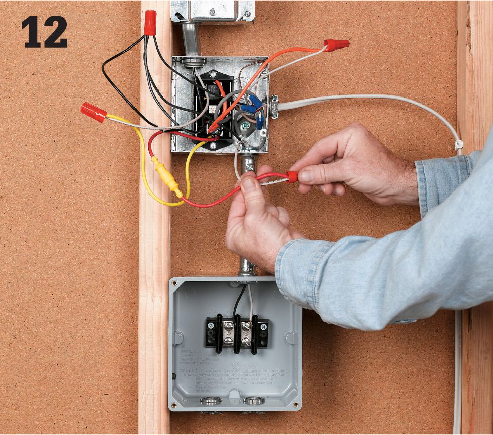
Wire the charge controller. Route two more #14-gauge wires from the bottom of the DC disconnect terminals into the 4" x junction box and connect to the "Solar Panel In" terminals on the charge controller. The black wire should connect to the negative terminal in the PVC box and the red to the positive lead on the charge controller. Finish wiring of the charge controller according to the line diagram provided with the type of controller purchased. Generally the load wires connect to the orange lead, and the red wire gets tied to the battery through a fuse.
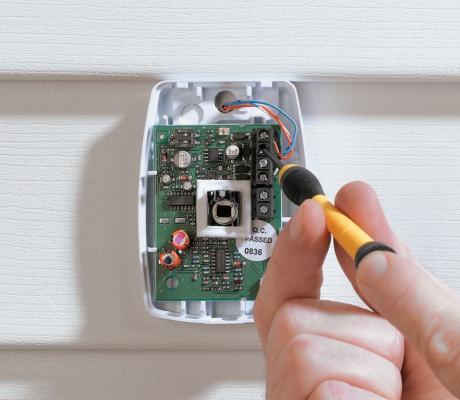
OPTION: Attach a motion sensor. Some charge controllers come equipped with a motion sensor to maximize the efficiency of your lighting system—these are especially effective when used with security lighting. The motion sensor is typically mounted to a bell box outside and wired directly to the charge controller with an 18-gauge x 3-conductor insulated cable. A system like this can support up to three motion sensors. Follow the manufacturer's directions for installing and wiring the motion sensor.
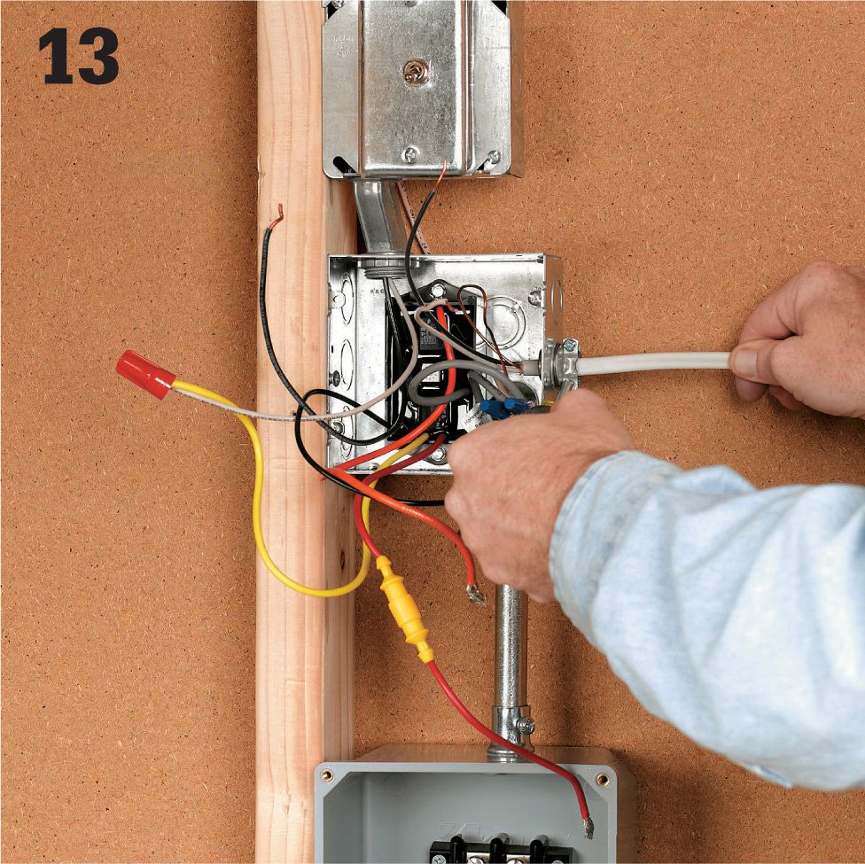
Run wiring to the loads (exterior DC lighting fixtures in this case) from the charge controller. DC light fixtures (12-volt) with LED bulbs can be purchased at marine and RV stores if you can't find them in your home center or electrical supply store. For more information on wiring exterior light fixtures, see pages 280 to 283.
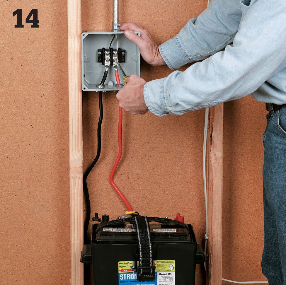
Install the battery. Here, a deep-cell 12-volt marine battery is used. First, cut and strip each of the two battery cables at one end and install into the battery control junction box through cord cap connectors. Terminate these wires on two separate, firmly mounted insulated terminal blocks.
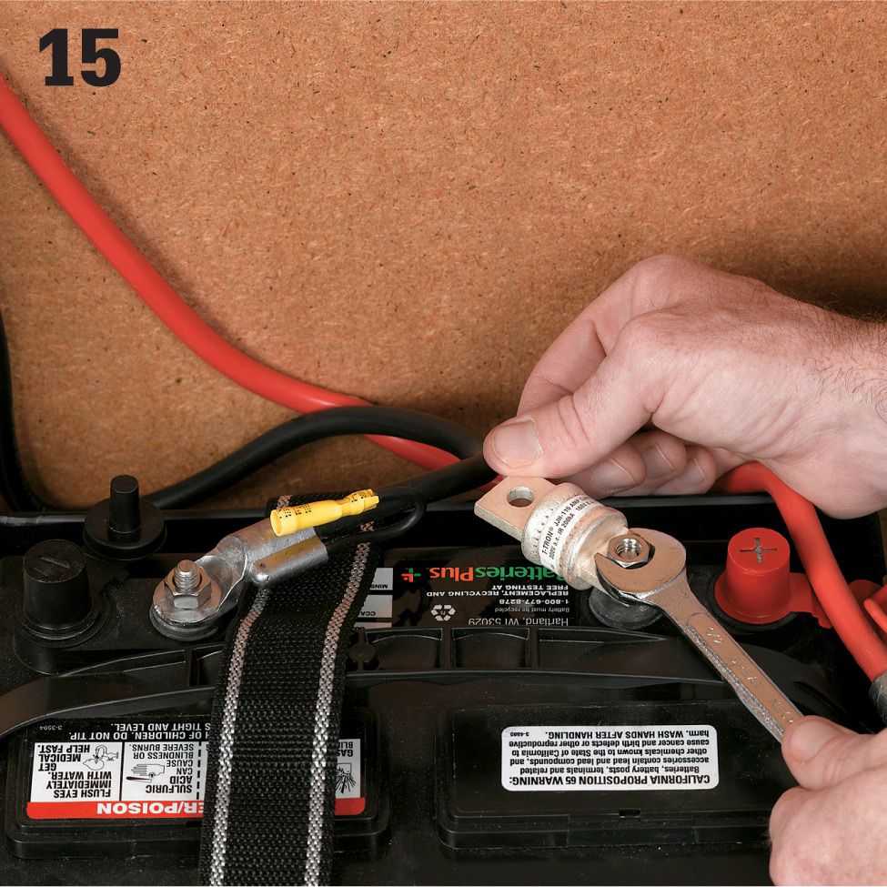
Install the catastrophe fuse onto the positive terminal using nuts and bolts provided with the battery cables. Connect the battery cables to the battery while paying close attention to the polarity (red to positive and black to negative). Make sure all connections have been made and double checked.
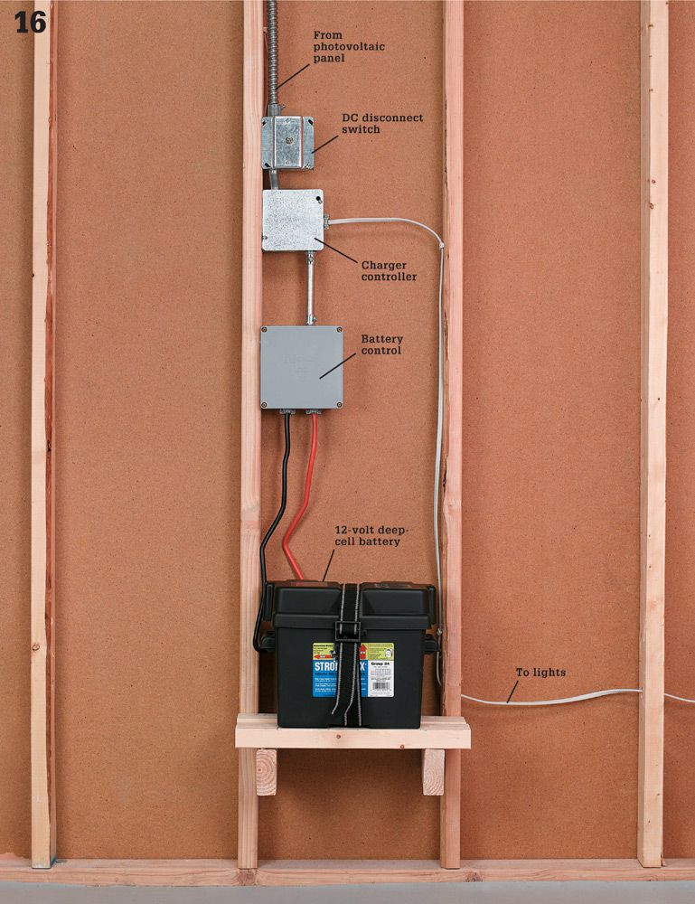
Cover all junction boxes, remove the bag from the panel, and turn the DC disconnect switch on to complete the circuit. Test the lights, and adjust the time to desired setting.