The Complete Guide to Wiring, Updated 6th Edition: Current with 2014-2017 Electrical Codes - Black & Decker, Cool Springs Press (2014)
Chapter 2. Wire, Cable & Conduit
Wire and cable comprise the electrical infrastructure in your home. Selecting the appropriate size and type and handling it correctly is absolutely necessary to a successful wiring project that will pass inspection.
Copper wire is the primary conductor of electricity in any home. The electricity itself travels on the outer surfaces of the wire, so insulation is normally added to the wires to protect against shock and fires. The insulated wires are frequently grouped together and bound up in rugged plastic sheathing according to gauge and function. Multiple wires housed in shared sheathing form a cable. In some cases, the wires are grouped in metal or plastic tubes known as conduit. Conduit (also known as raceway) is used primarily in situations where the cables or wires are exposed, such as open garage walls.
This chapter introduces some of the many varieties of wire, cable, and conduit used in home construction and explains which types to use where. It also will demonstrate the essential skills used to run new cable, install conduit, strip sheathing, make wire connections, and more.
In this chapter:
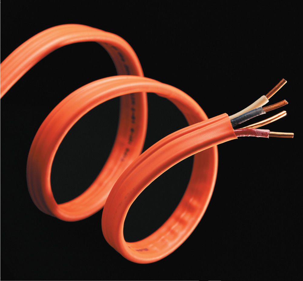
![]() Wire & Cable
Wire & Cable
![]() NM Cable
NM Cable
![]() Conduit
Conduit
![]() Surface-Mounted Wiring
Surface-Mounted Wiring
![]() Wire & Cable
Wire & Cable
Wires are made of copper, aluminum, or aluminum covered with a thin layer of copper. Solid copper wires are the best conductors of electricity and are the most widely used. Aluminum and copper-covered aluminum wires require special installation techniques.
A group of two or more wires enclosed in a metal, rubber, or plastic sheath is called a cable (see photo, opposite page). The sheath protects the wires from damage. Conduit also protects wires, but it is not considered a cable.
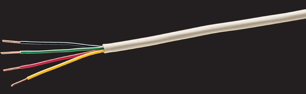
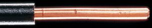
Individual wires are covered with rubber or plastic vinyl insulation. An exception is a bare copper grounding wire, which does not need an insulation cover. The insulation is color coded (see chart, below left) to identify the wire as a hot wire, a neutral wire, or a grounding wire. New cable sheathing is also color coded to indicate the size of the wires inside. White means #14 wire, yellow means #12 wire, and red means #10 wire.
In most wiring systems installed after 1965, the wires and cables are insulated with plastic vinyl. This type of insulation is very durable and can last as long as the house itself.
Before 1965, wires and cables were insulated with rubber. Rubber insulation has a life expectancy of about 25 years. Old insulation that is cracked or damaged can be reinforced temporarily by wrapping the wire with plastic electrical tape. However, old wiring with cracked or damaged insulation should be inspected by a qualified electrician to make sure it is safe.
Wires must be large enough for the amperage rating of the circuit (see chart, below right). A wire that is too small can become dangerously hot. Wire sizes are categorized according to the American Wire Gauge (AWG) system. To check the size of a wire, use the wire stripper openings of a combination tool (see page 30) as a guide.
Wire Color Chart ![]()
|
WIRE COLOR |
FUNCTION |
|
|
Neutral wire carrying current at zero voltage |
|
|
Hot wire carrying current at full voltage |
|
|
Hot wire carrying current at full voltage |
|
|
Hot wire carrying current at full voltage |
|
|
Serves as a bonding pathway |
|
|
Serves as a bonding pathway |
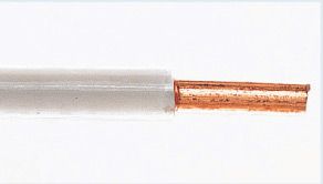 White or gray
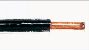 Black
Black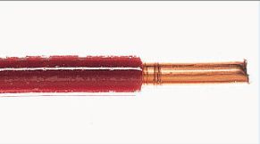 Red
Red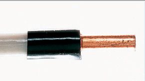 White, black markings
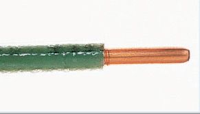 Green
Green Bare copper
Individual wires are color-coded to identify their function. In some circuit installations, the white wire serves as a hot wire that carries voltage. If so, this white wire may be labeled with black tape or paint to identify it as a hot wire.
Wire Size Chart ![]()
|
WIRE GAUGE |
WIRE CAPACITY & USE |
|
|
55 amps, 240 volts; central air conditioner, electric furnace |
|
|
40 amps, 240 volts; electric range, central air conditioner |
|
|
30 amps, 240 volts; window air conditioner, clothes dryer |
|
|
20 amps, 120 volts; light fixtures, receptacles, microwave oven |
|
|
15 amps, 120 volts; light fixtures, receptacles |
|
|
Light-duty extension cords |
|
|
Thermostats, doorbells, to 22 security systems |
 #6
#6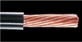 #8
#8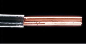 #10
#10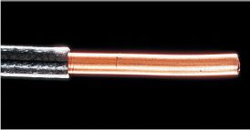 #12
#12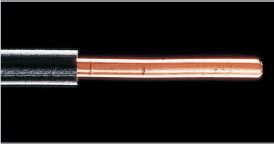 #14
#14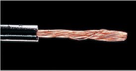 #16
#16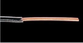 #18 to 22
Wire sizes (shown actual size) are categorized by the American Wire Gauge system. The larger the wire size, the smaller the AWG number. The ampacities in this table are for copper wires in NM cable. The ampacity for the same wire in conduit is usually more. The ampacity for aluminum wire is less.
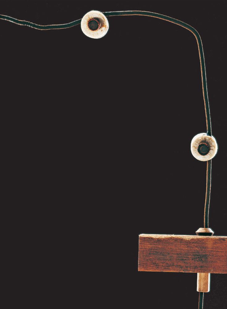
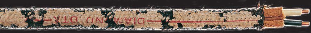
Knob and tube wiring, so called because of the shape of its porcelain insulating brackets, was common before 1940. Wires are covered with a layer of rubberized cloth, but have no additional protection.

Metal clad cable (MC) and armored cable (AC) have been around since the 1920s. Early versions had no grounding function, but existed solely to protect the wires that were threaded into it. Later armored cable products either had ground wire twisted in with the flexible metal cover or relied on the metal cover itself for connecting to ground. Modern MC contains an insulated ground wire along with the conductors.
Metal conduit was installed during the middle of the 20th century as a way to protect hot and neutral conductors. The conduit itself often was employed for connecting to ground. Modern conduit (both metal and PVC) should be filled with insulated THHN conductors, including an insulated ground wire.
Early NM (nonmetallic) cable was used from 1930 until 1965. It features a rubberized fabric sheathing that protects individual wires. NM cable greatly simplified installations because separate wires no longer had to be pulled by hand through a conduit or armored cable. Early NM cable had no grounding wire.

NM cable was developed around 1930. The first version had rubberized sheathing that degraded rapidly and had no ground wire. Modern versions with a hard PVC shell came onto the market in the 1960s. Sheathing is now color-coded by gauge (the yellow seen here is 12 AWG).
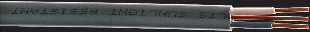
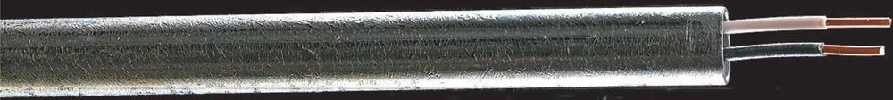
UF (underground feeder) cable has wires embedded in a solid-core plastic vinyl sheathing and includes a bare copper grounding wire. It is designed for installations in damp conditions, such as buried circuits.
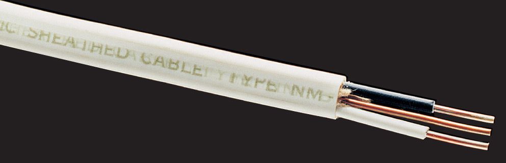
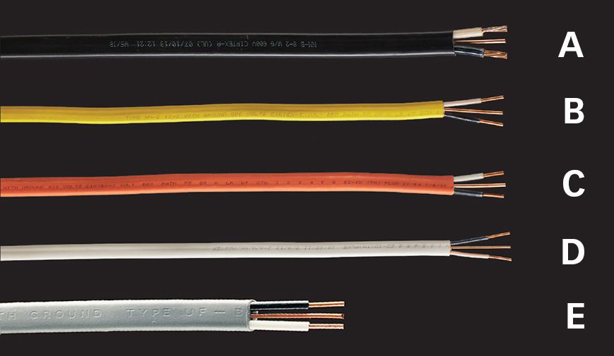
NM (nonmetallic) sheathed cable should be used for most indoor wiring projects in dry locations. NM cable is available in a wide range of wire sizes and in either “2-wire with ground” or “3-wire with ground” types. NM cable is sold in boxed rolls that contain from 25 to 250 ft. of cable.
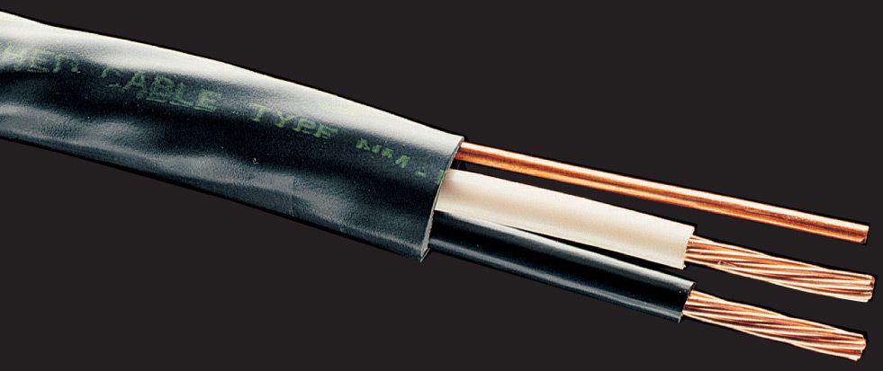
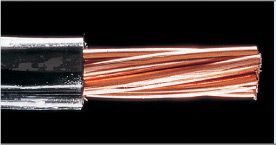
Service entrance cable (SE) is used between the electric utility’s service wires and the home’s main electrical panel. It can also be used for kitchen ranges and other 50-amp or 60-amp appliances that require 8-gauge or larger wire. It is similar to NM cable, but each individual conducting wire is made from fine-stranded copper wires. SE cable is available in both 2-wire and 3-wire types.
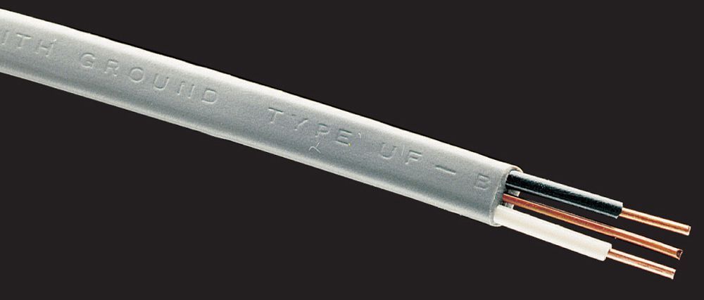
UF cable is used for wiring in damp locations, such as in an outdoor circuit. It has a white or gray solid-core vinyl sheathing that protects the wires inside. It also can be used indoors wherever NM cable is allowed.
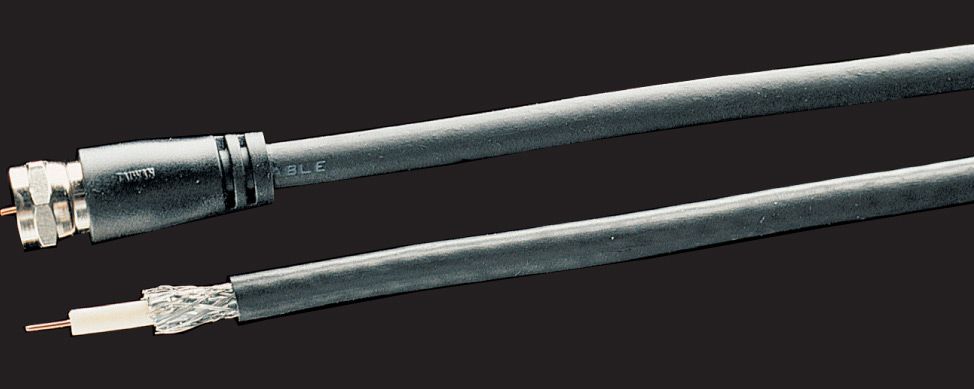
Coaxial cable is used to connect cable television jacks. It is available in lengths up to 25 ft. with preattached F-connectors (A). or you can buy bulk cable (B) in any length.
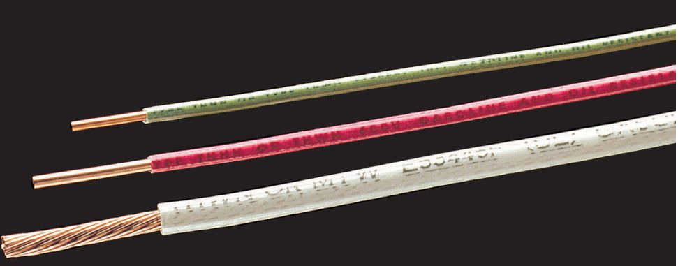
THHN/THWN wire can be used in all conduit applications. Each wire, purchased individually, is covered with a color-coded thermoplastic insulating jacket. Make sure the wire you buy has the THHN/THWN rating. other wire types are less resistant to heat and moisture than THHN/THWN wire.
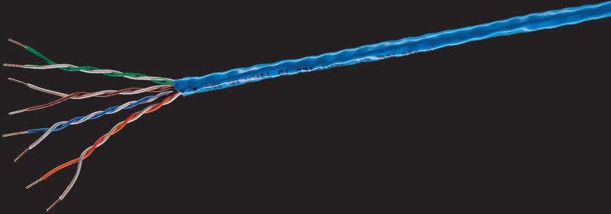
Cat 5 (Category 5) cable is used mostly for information and data networks. The cable contains four pairs of twisted copper wire with color-coded insulation.
Telephone cable is used to connect telephone outlets. your phone company may recommend four-wire cable (shown below) or eight-wire cable, sometimes called four-pair. Eight-wire cable has extra wires that are left unattached. These extra wires allow for future expansion of the system.
![]() NM Sheathing Colors
NM Sheathing Colors
The PVC sheathing for NM cable is coded by color so wiring inspectors can tell what the capacity of the cable is at a glance.
(A) Black = 6 or 8 AWG conductors
(B) Yellow = 12 AWG conductors
(C) Orange = 10 AWG conductors
(D) White = 14 AWG conductors
E) Gray = UF cable (see photo above)
![]() Reading NM (Nonmetallic) Cable
Reading NM (Nonmetallic) Cable
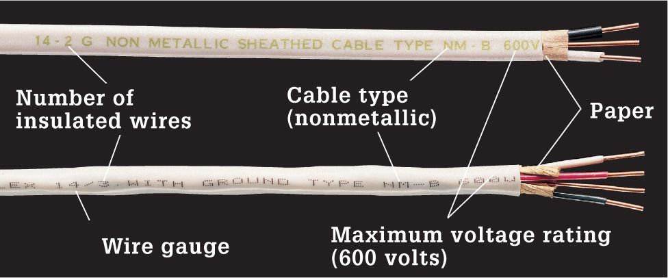
NM cable is labeled with the number of insulated wires it contains. The bare grounding wire is not counted. For example, a cable marked 14/2 G (or 14/2 WITH GROUND) contains two insulated 14-gauge wires, plus a bare copper grounding wire. Cable marked 14/3 WITH GROUND has three 14-gauge wires plus a grounding wire. NM cable also is stamped with a maximum voltage rating, as determined by Underwriters Laboratories (UL).
![]() Reading Unsheathed, Individual Wire
Reading Unsheathed, Individual Wire
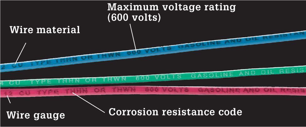
Unsheathed, individual wires are used for conduit and raceway installations. Wire insulation is coded with letters to indicate resistance to moisture, heat, and gas or oil. Code requires certain letter combinations for certain applications. T indicates thermoplastic insulation. H stands for heat resistance, and two Hs indicate high resistance (up to 194° F). W denotes wire suitable for wet locations. Wire coded with an N is impervious to damage from oil or gas.
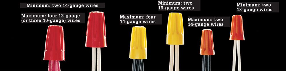
Use wire connectors rated for the wires you are connecting. Wire connectors are color-coded by size, but the coding scheme varies according to manufacturer. The wire connectors shown above come from one major manufacturer. To ensure safe connections, each connector is rated for both minimum and maximum wire capacity. These connectors can be used to connect both conducting wires and grounding wires. Green wire connectors are used only for grounding wires.
Tips for Working with Wire ![]()
|
WIRE GAUGE |
AMPACITY |
MAXIMUM WATTAGE LOAD |
|
|
15 amps |
1,440 watts (120 volts) |
|
|
20 amps |
1,920 watts (120 volts) |
|
|
30 amps |
2,880 watts (120 volts) |
|
|
40 amps |
7,680 watts (240 volts) |
|
|
55 amps |
10,560 watts (240 volts) |
 14-gauge
 12-gauge
 10-gauge
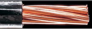 8-gauge
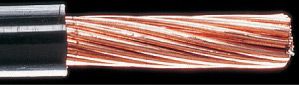 6-gauge
Wire “ampacity” is a measurement of how much current a wire can carry safely. Ampacity varies by the size of the wires. When installing a new circuit, choose wire with an ampacity rating matching the circuit size. For dedicated appliance circuits, check the wattage rating of the appliance and make sure it does not exceed the maximum wattage load of the circuit. The ampacities in this table are for copper wires in NM cable. The ampacity for the same wire in conduit is usually more. The ampacity for aluminum wire is less.
![]() How to Strip NM Sheathing & Insulation
How to Strip NM Sheathing & Insulation
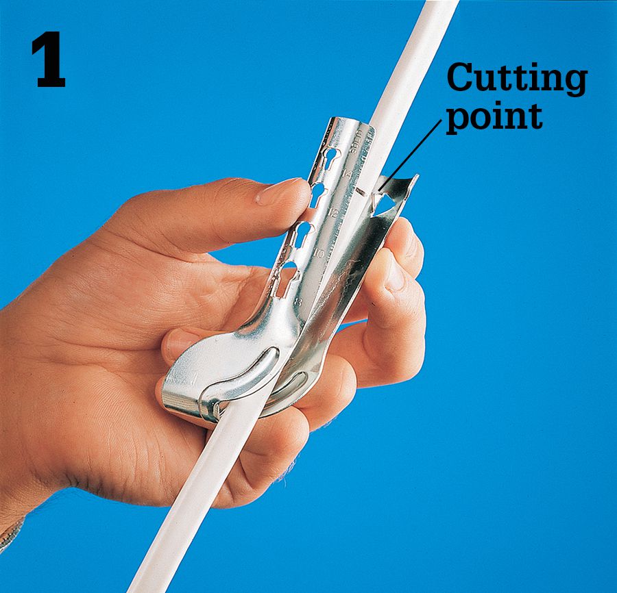
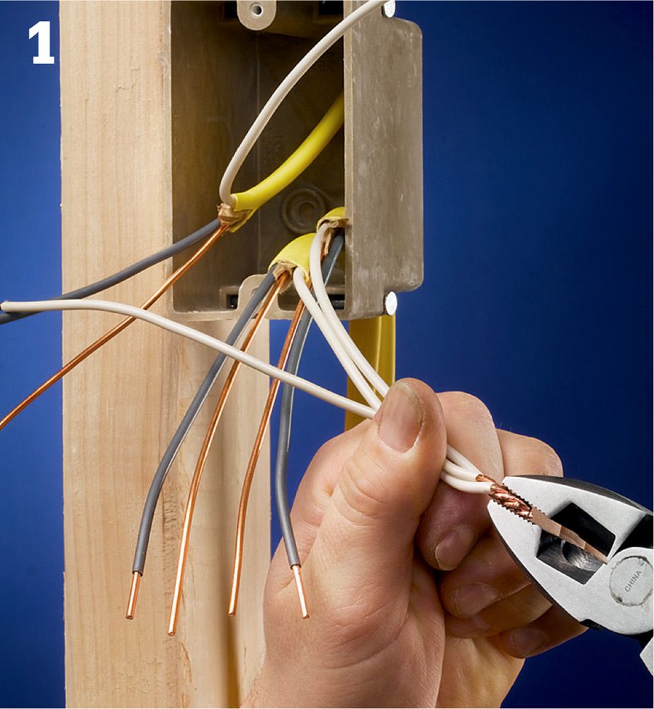
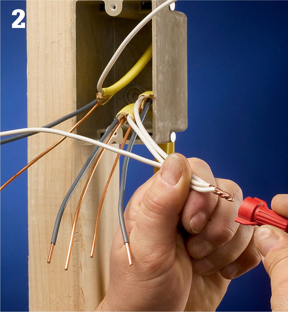
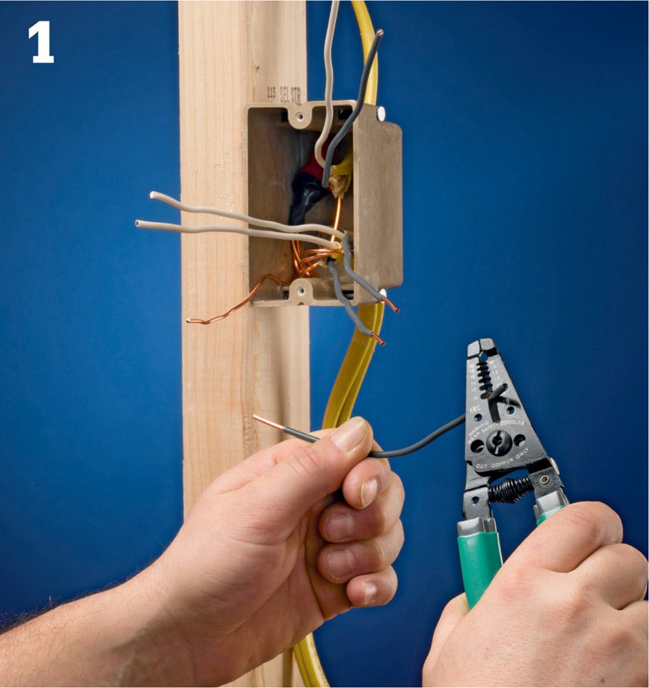
Measure and mark the cable 8 to 10” from the end. Slide the cable ripper onto the cable, and squeeze tool firmly to force the cutting point through the plastic sheathing.
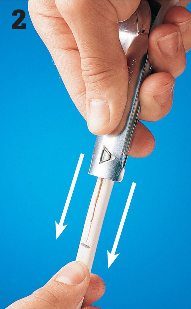
Grip the cable tightly with one hand, and pull the cable ripper toward the end of the cable to cut open the plastic sheathing.
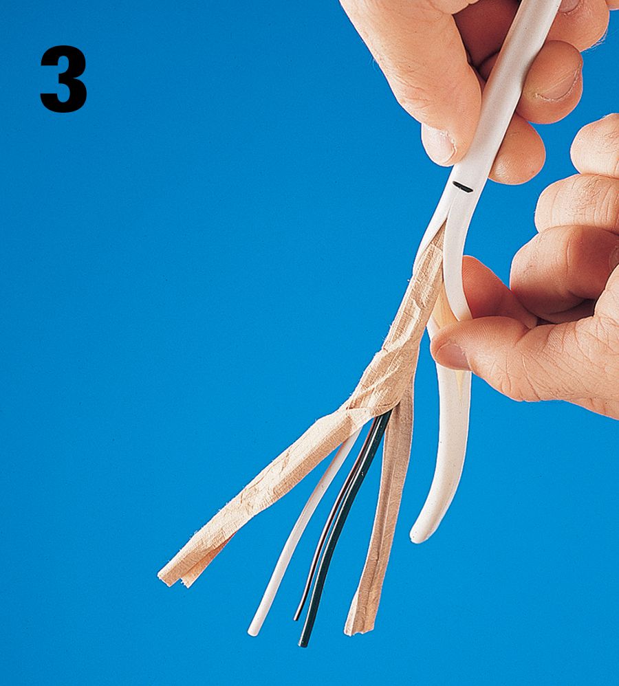
Peel back the plastic sheathing and the paper wrapping from the individual wires.
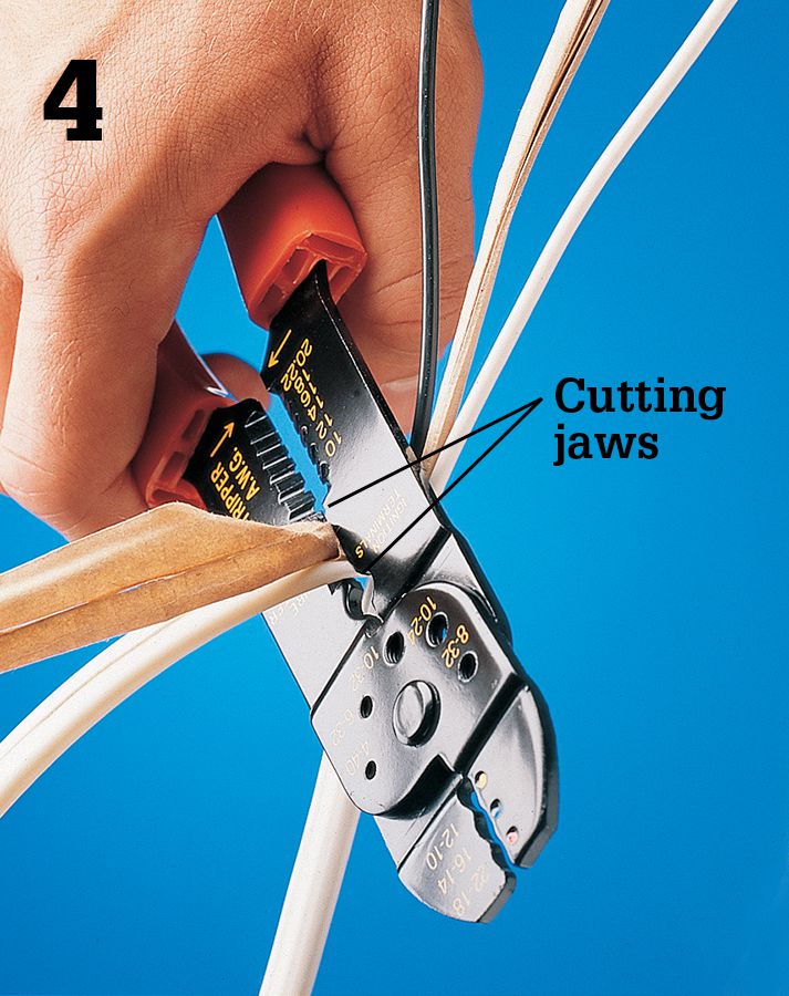
Cut away the excess plastic sheathing and paper wrapping using the cutting jaws of a combination tool.
Cut individual wires as needed using the cutting jaws of the combination tool. Leave a minimum of 3” of wire running past the edge of the box.
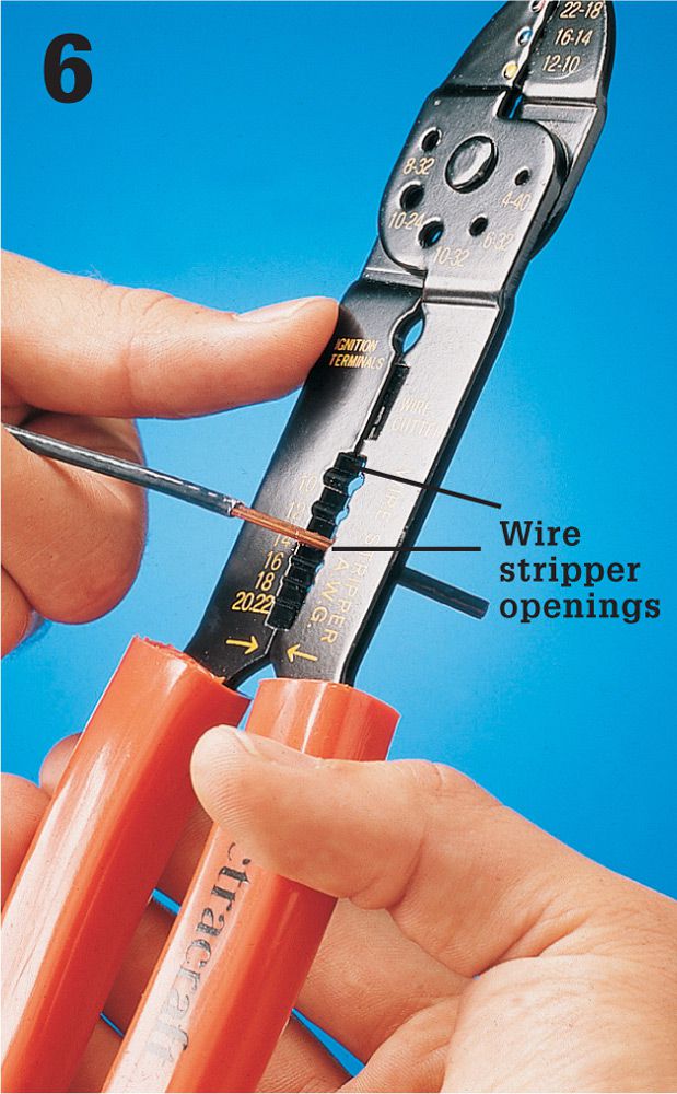
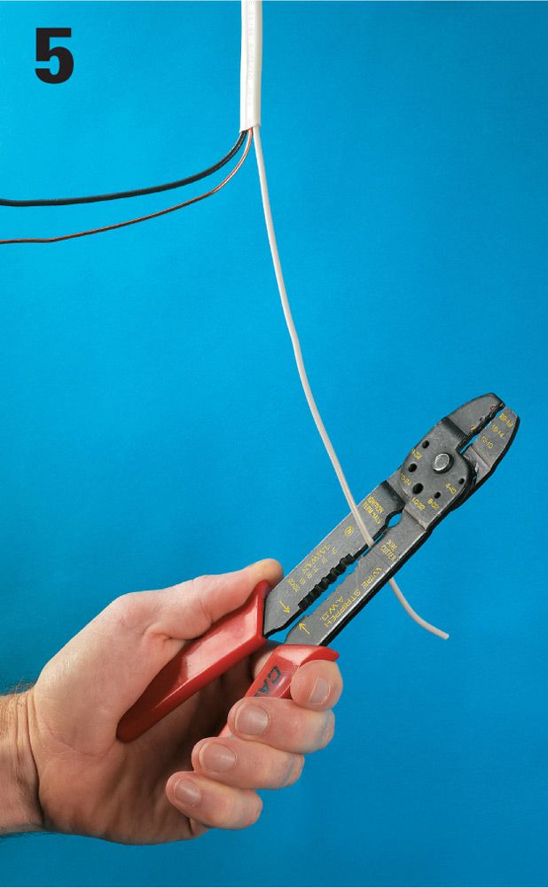
Strip insulation for each wire using the stripper openings. Choose the opening that matches the gauge of the wire, and take care not to nick or scratch the ends of the wires.
![]() How to Connect Wires to Screw Terminals
How to Connect Wires to Screw Terminals
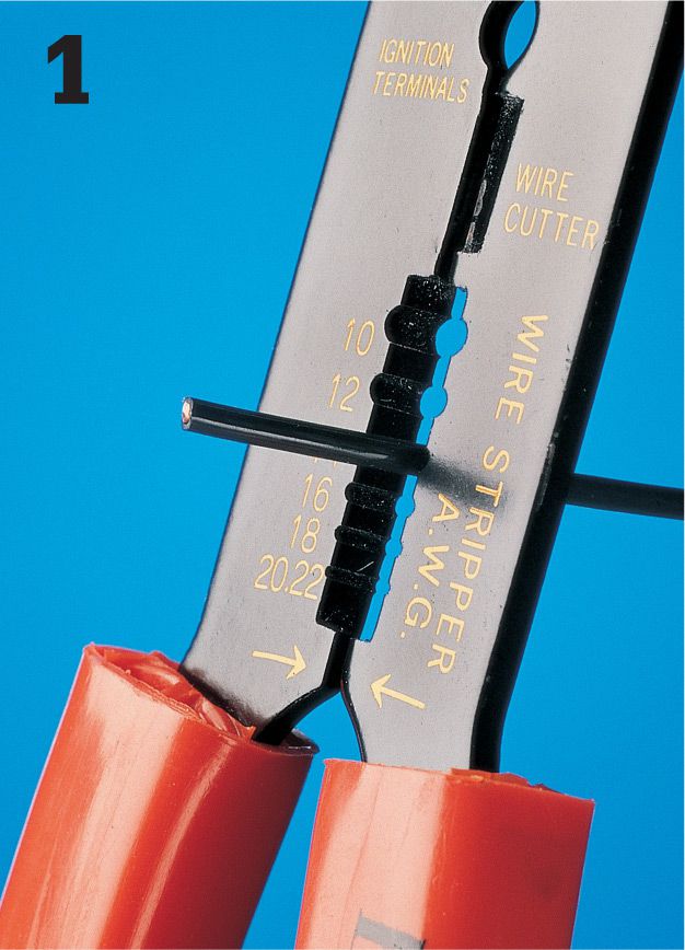
Strip about 3/4 of insulation from each wire using a combination tool. Choose the stripper opening that matches the gauge of the wire, and then clamp the wire in the tool. Pull the wire firmly to remove plastic insulation.
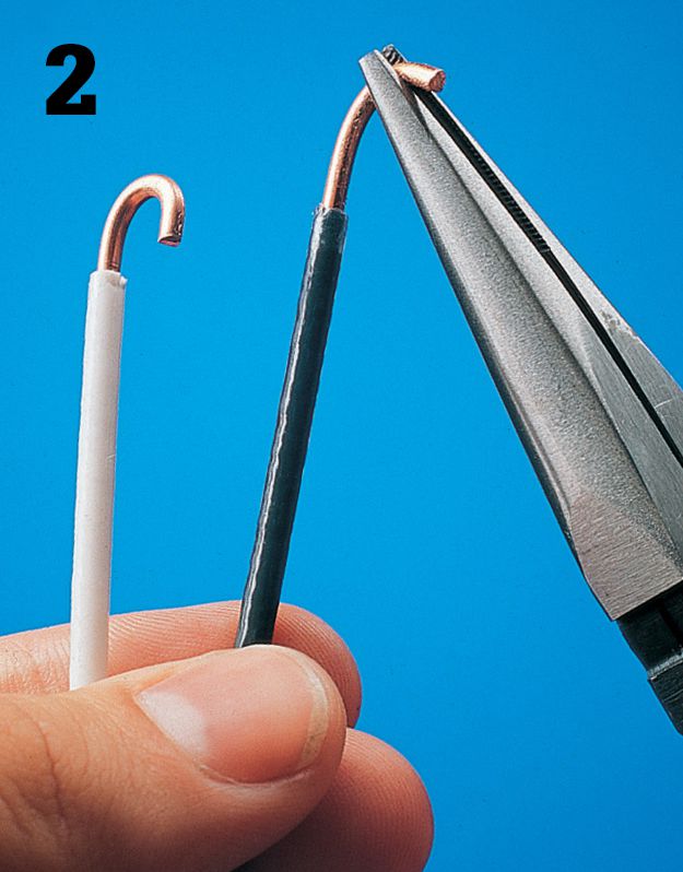
Form a C-shaped loop in the end of each wire using a needlenose pliers or the hole of the correct gauge in a pair of wire strippers. The wire should have no scratches or nicks.
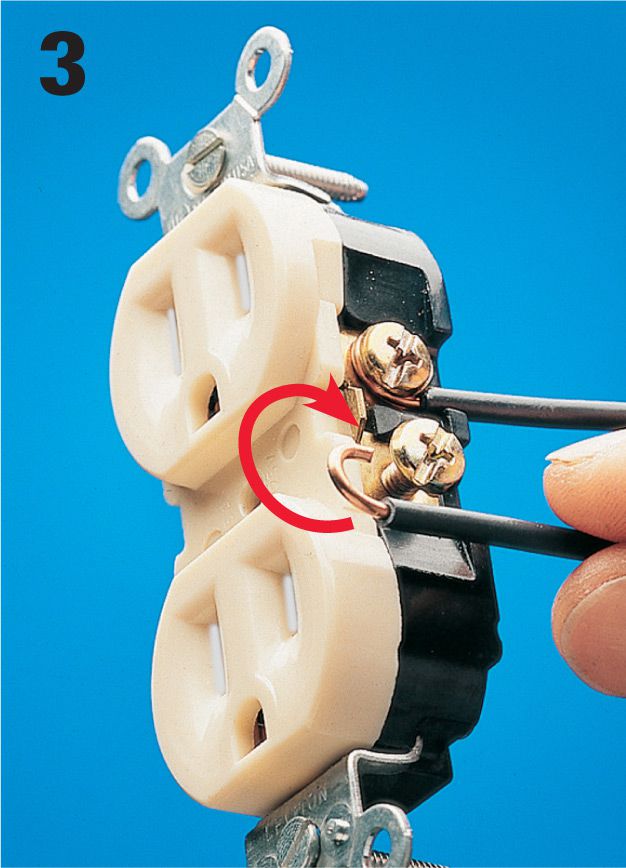
Hook each wire around the screw terminal so it forms a clockwise loop. Tighten the screw firmly. Insulation should just touch head of screw. Never place the ends of two wires under a single screw terminal. Instead, use a pigtail wire (see page 35).
Cable Staples ![]()
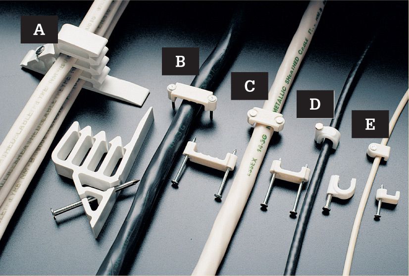
Use plastic cable staples to fasten cables. Choose staples sized to match the cables. Stack-It® staples (A) hold up to four 2-wire cables; 3/4" staples (B) for 12/2, 12/3, and all 10-gauge cables; 1/2" staples (C) for 14/2, 14/3, or 12/2 cables; coaxial staples (D) for anchoring television cables; bell wire staples (E) for attaching telephone cables.
Push-in connectors ![]()
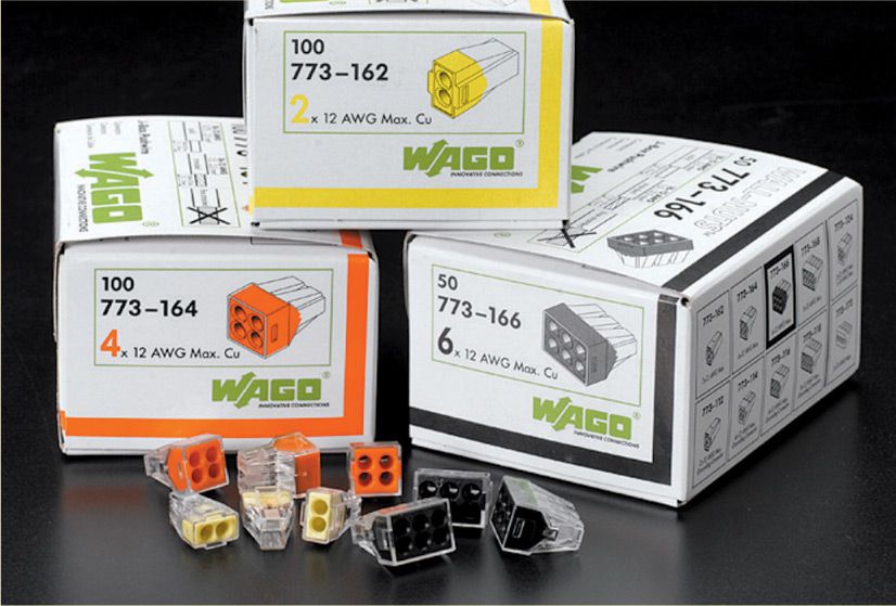
Push-in connectors are a relatively new product for joining wires. Instead of twisting the bare wire ends together, you strip off about 3/4" of insulation and insert them into a hole in the connector. The connectors come with two to four holes sized for various gauge wires. These connectors are perfect for inexperienced DIYers, because they do not pull apart like a sloppy twisted connection can.
![]() How to Join Wires with a Wire Connector
How to Join Wires with a Wire Connector
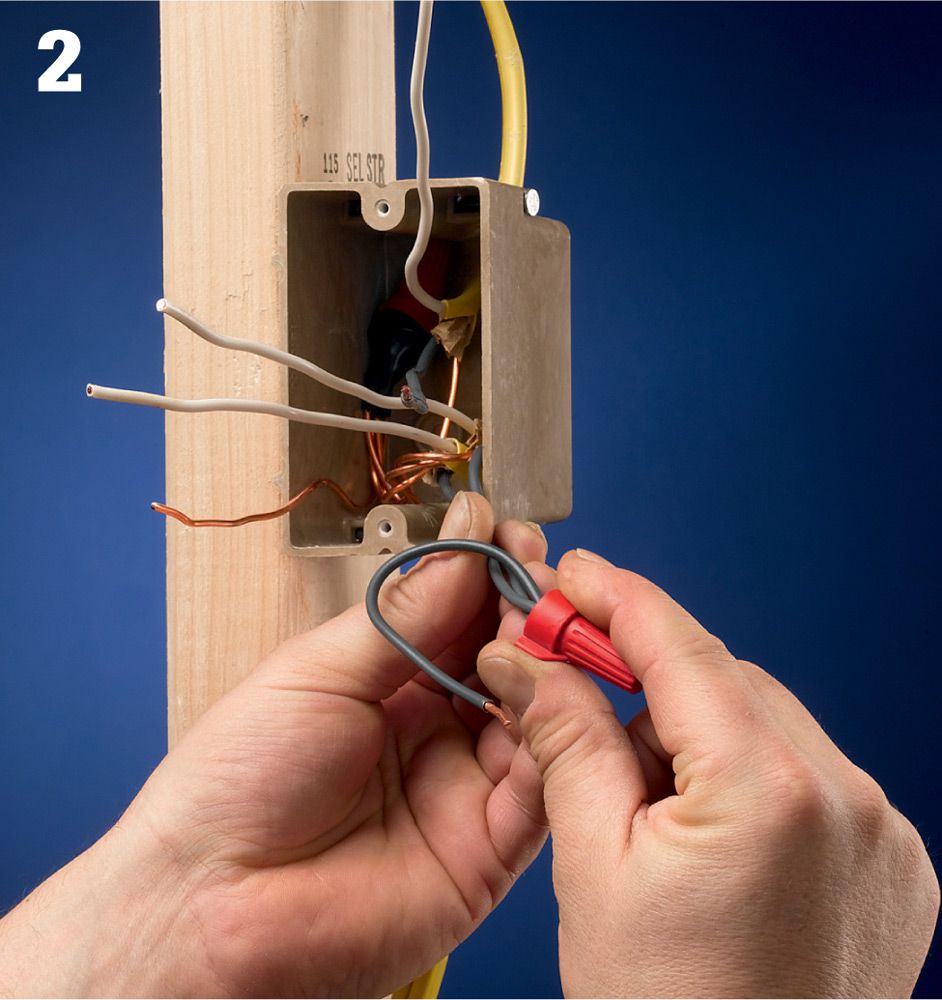
Ensure power is off and test for power. Grasp the wires to be joined in the jaws of a pair of linesman’s pliers. The ends of the wires should be flush and they should be parallel and touching. Rotate the pliers clockwise two or three turns to twist the wire ends together.
Twist a wire connector over the ends of the wires. Make sure the connector is the right size (see page 29). Hand-twist the connector as far onto the wires as you can. There should be no bare wire exposed beneath the collar of the connector.
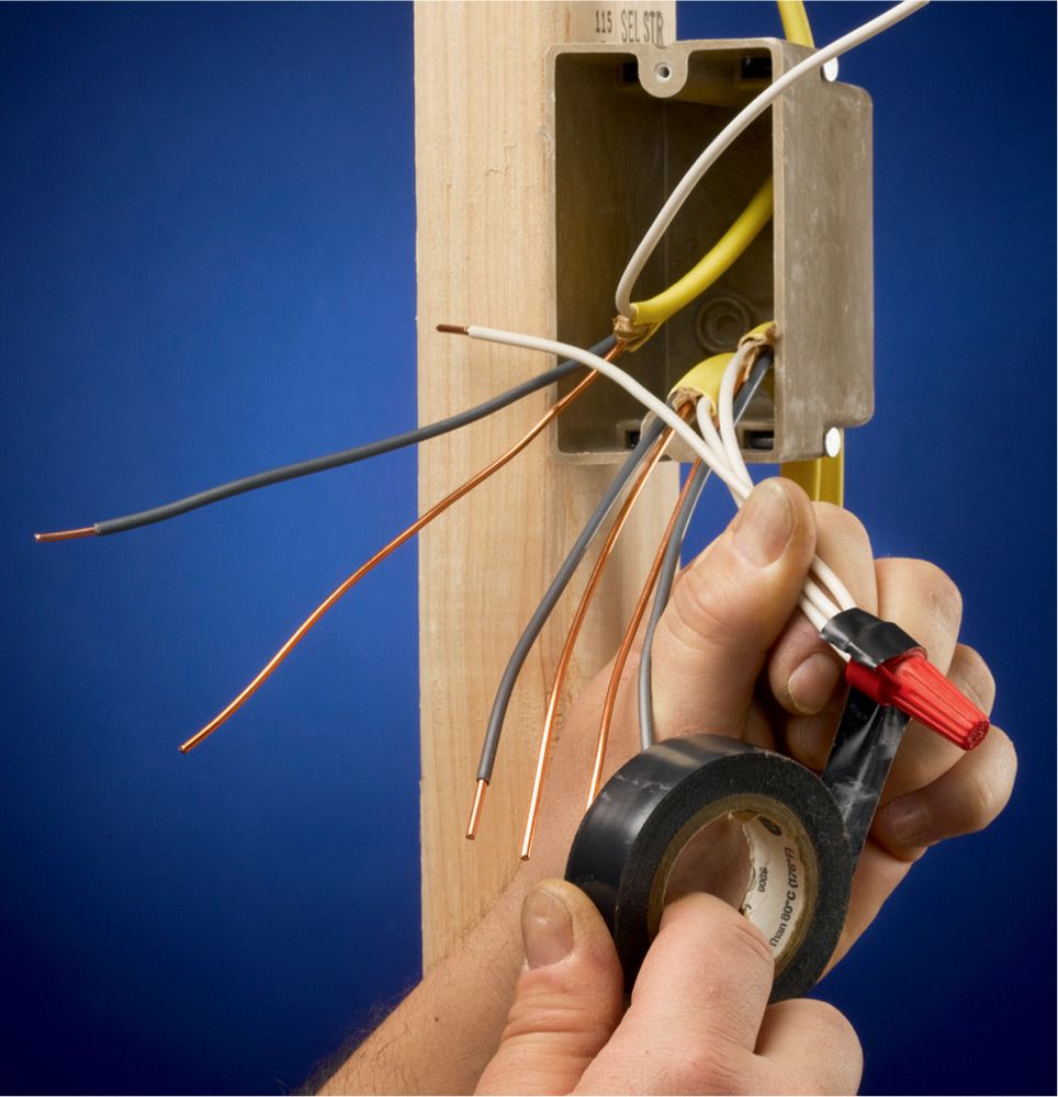
Option: Reinforce the joint by wrapping it with electrician’s tape. By code, you cannot bind the wire joint with tape only, but it can be used as insurance. Few professional electricians use tape for purposes other than tagging wires for identification.
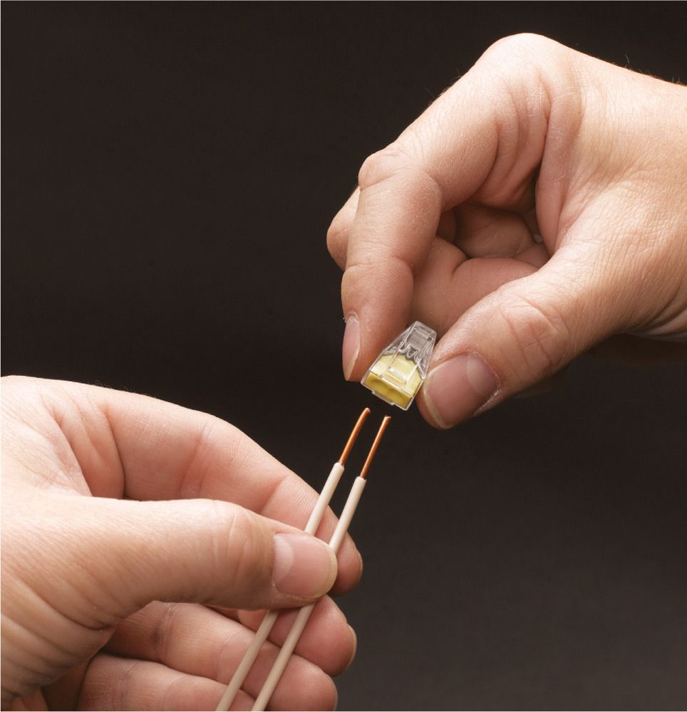
Option: Strip 3/4" of insulation off the ends of the wires to be joined, and insert each wire into a push-in connector. Gently tug on each wire to make sure it is secure.
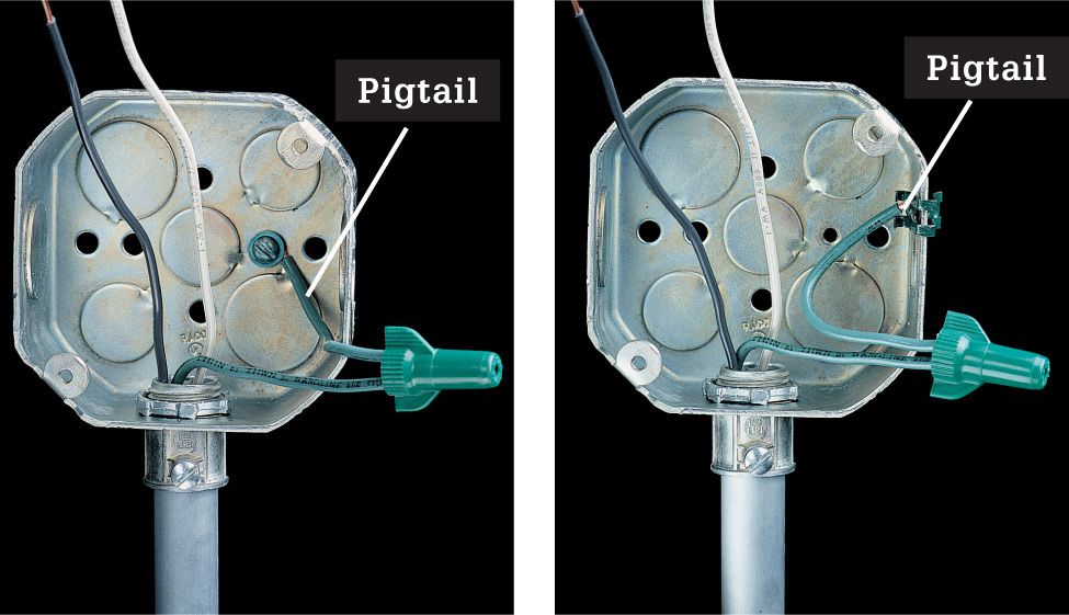
![]() How to Pigtail Wires
How to Pigtail Wires
Cut a 6" length from a piece of insulated wire the same gauge and color as the wires it will be joining. Strip 3/4" of insulation from each end of the insulated wire. Note: Pigtailing is done mainly to avoid connecting multiple wires to one terminal, which is a code violation.
Join one end of the pigtail to the wires that will share the connection using a wire nut.
Alternative: If you are pigtailing to a grounding screw or grounding clip in a metal box, you may find it easier to attach one end of the wire to the grounding screw before you attach the other end to the other wires.
Connect the pigtail to the appropriate terminal on the receptacle or switch. Fold the wires neatly and press the fitting into the box.
![]() NM Cable
NM Cable
Non-metallic (NM) cable is used for most indoor wiring projects except those requiring conduit and those in damp areas such as against concrete or masonry walls with dirt on the other side. Cut and install the cable after all electrical boxes have been mounted. Refer to your wiring plan to make sure each length of cable is correct for the circuit size and configuration.
Cable runs are difficult to measure exactly, so leave plenty of extra wire when cutting each length. Cable splices inside walls are not allowed by code. When inserting cables into a circuit breaker panel, make sure the power is shut off.
After all cables are installed and all the ground wires spliced, call your electrical inspector to arrange for the rough-in inspection. Do not install wallboard or attach light fixtures and other devices until this inspection is done. Check with your building inspector before using NM cable. Some areas, such as the Chicago area, do not allow NM cable.
Tools & Materials ![]()
Drill and bits
Tape measure
Cable ripper
Combination tool
Screwdrivers
Needlenose pliers
Hammer
Fish tape
NM cable
Cable clamps
Cable staples
Masking tape
Electrical tape
Grounding pigtails
Wire connectors
Eye and ear protection
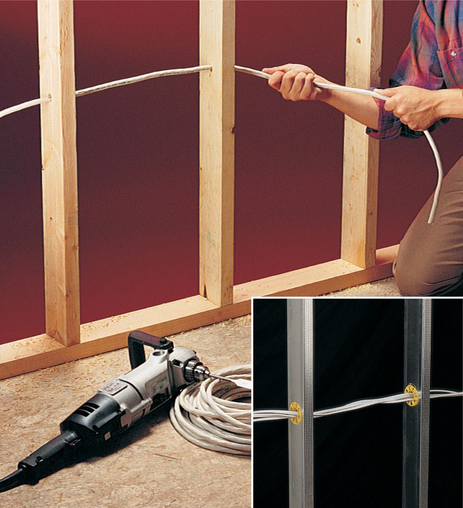
Pulling cables through studs is easier if you drill smooth, straight holes at the same height. Prevent kinks by straightening the cable before pulling it through the studs. Use plastic grommets to protect cables on steel studs (inset).
|
Framing Member |
2 × 4 loadbearing stud |
|
Maximum Hole Size |
1 1/16"diameter |
|
Maximum Notch Size |
1/8" deep |
|
Framing Member |
2 × 4 non-loadbearing stud |
|
Maximum Hole Size |
2 1/8" diameter |
|
Maximum Notch Size |
1 1/16" deep |
|
Framing Member |
2 × 6 loadbearing stud |
|
Maximum Hole Size |
2 3/16" diameter |
|
Maximum Notch Size |
1 3/8" deep |
|
Framing Member |
2 × 6 non-loadbearing stud |
|
Maximum Hole Size |
3 5/16" diameter |
|
Maximum Notch Size |
2 3/16" deep |
|
Framing Member |
2 × 6 joists |
|
Maximum Hole Size |
1 13/16" diameter |
|
Maximum Notch Size |
15/16" deep |
|
Framing Member |
2 × 8 joists |
|
Maximum Hole Size |
2 1/2" diameter |
|
Maximum Notch Size |
1 1/4" deep |
|
Framing Member |
2 × 10 joists |
|
Maximum Hole Size |
3 1/16" diameter |
|
Maximum Notch Size |
1 9/16" deep |
|
Framing Member |
2 × 12 joists |
|
Maximum Hole Size |
3 3/4" diameter |
|
Maximum Notch Size |
1 7/8" deep |
This framing member chart shows the maximum sizes for holes and notches that can be cut into studs and joists when running cables. When boring holes, there must be at least 5/8" of wood between the edge of a stud and the hole and at least 2" between the edge of a joist and the hole. Joists can be notched only in the end third of the overall span; never in the middle third of the joist. If 1 1/4" clearance cannot possibly be maintained, you may be able to satisfy code by installing a metal nail plate over the point of penetration in the stud or joist. Different rules apply to wood I-joists, metal-plate-connected trusses, engineered beams, and beams assembled from lumber. In general, you may not drill and notch trusses and assembled beams. Manufacturers of I-joists and engineered beams have limits about the size and location of holes.
![]() How to Install NM Cable
How to Install NM Cable
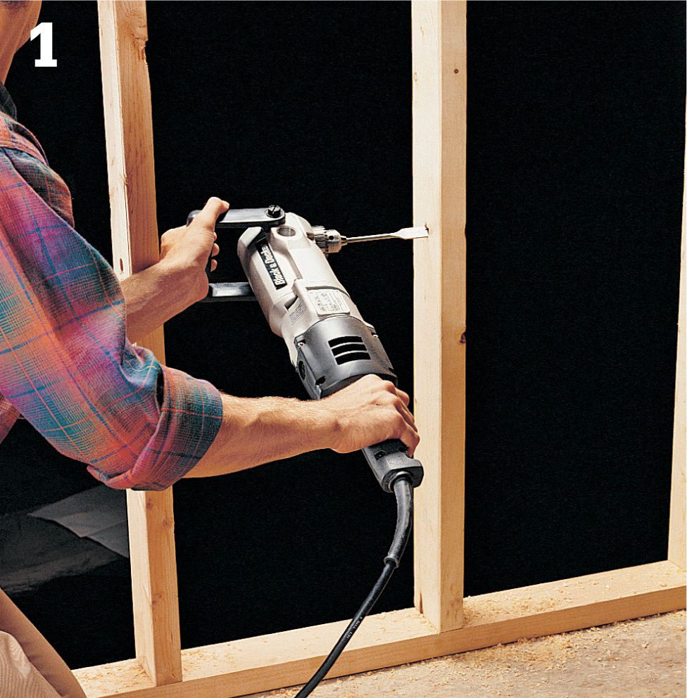
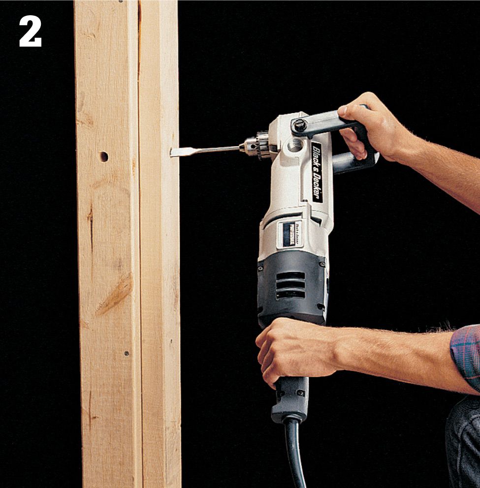
Drill 5/8" holes in framing members for the cable runs. This is done easily with a right-angle drill, available at rental centers. Holes should be set back at least 1 1/4" from the front face of the framing members.
Where cables will turn corners (step 6, page 36), drill intersecting holes in adjoining faces of studs. Measure and cut all cables, allowing 2 ft. extra at ends entering the breaker panel and 1 foot for ends entering the electrical box.
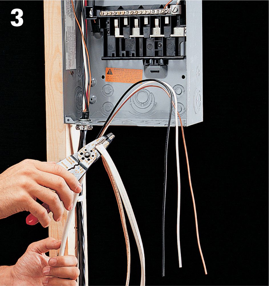
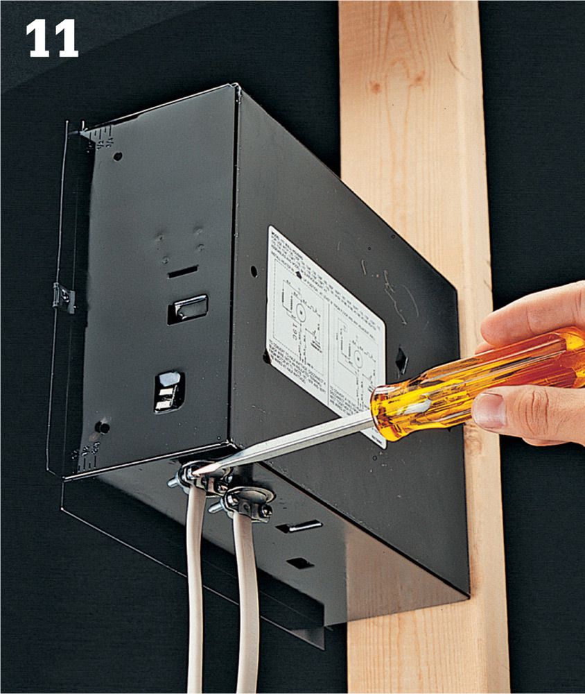
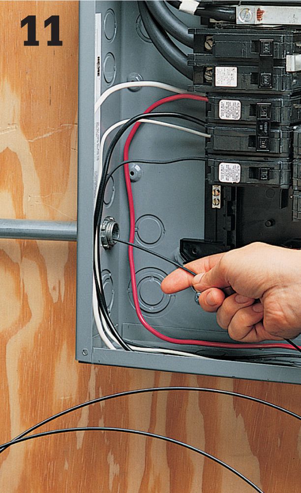
Shut off power to the circuit breaker panel. Use a cable ripper to strip the cable, leaving at least 1/4" of sheathing to enter the circuit breaker panel. Clip away the excess sheathing.
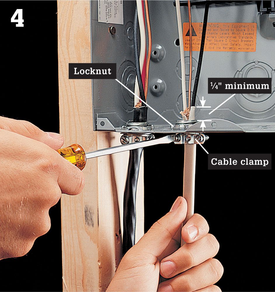
Open a knockout in the circuit breaker panel using a hammer and screwdriver. Insert a cable clamp into the knockout, and secure it with a locknut. Insert the cable through the clamp so that at least 1/4" of sheathing extends inside the circuit breaker panel. Tighten the mounting screws on the clamp so the cable is gripped securely but not so tightly that the sheathing is crushed.
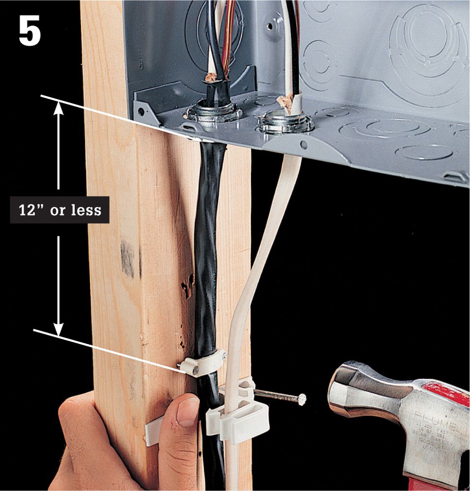
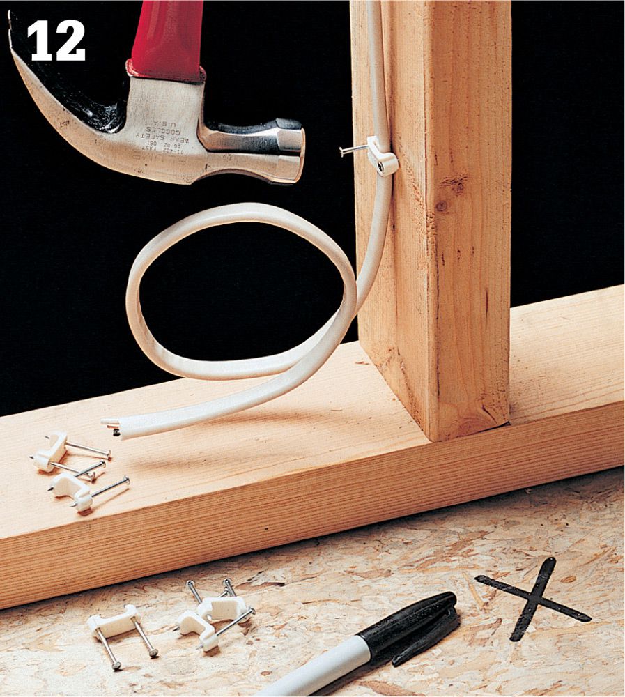
Anchor the cable to the center of a framing member within 12" of the circuit breaker panel using a cable staple. Stack-It® staples work well where two or more cables must be anchored to the same side of a stud. Run the cable to the first electrical box. Where the cable runs along the sides of framing members, anchor it with cable staples no more than 4 ft. 6 in. apart.
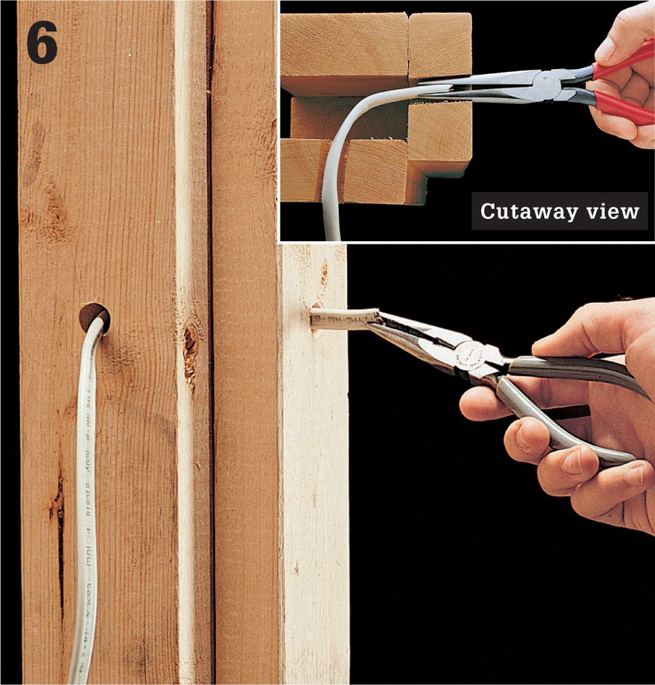
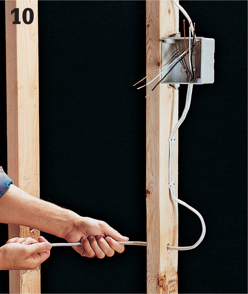
At corners, form a slight L-shaped bend in the end of the cable and insert it into one hole. Retrieve the cable through the other hole using needlenose pliers (inset).
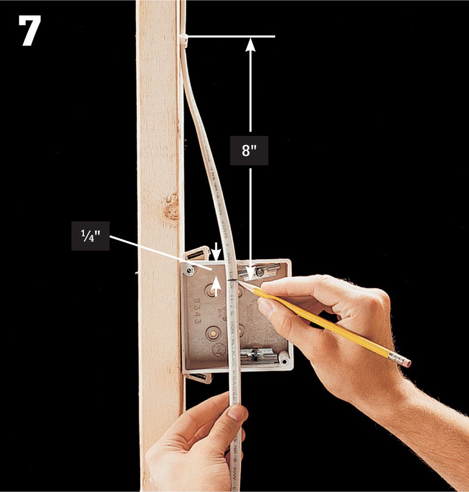
Staple the cable to a framing member within 8” from where the sheathing ends in the box. Hold the cable taut against the front of the box, and mark a point on the sheathing 1/4" past the box edge. Remove sheathing from the marked line to the end using a cable ripper, and clip away excess sheathing with a combination tool. Insert the cable through the knockout in the box.
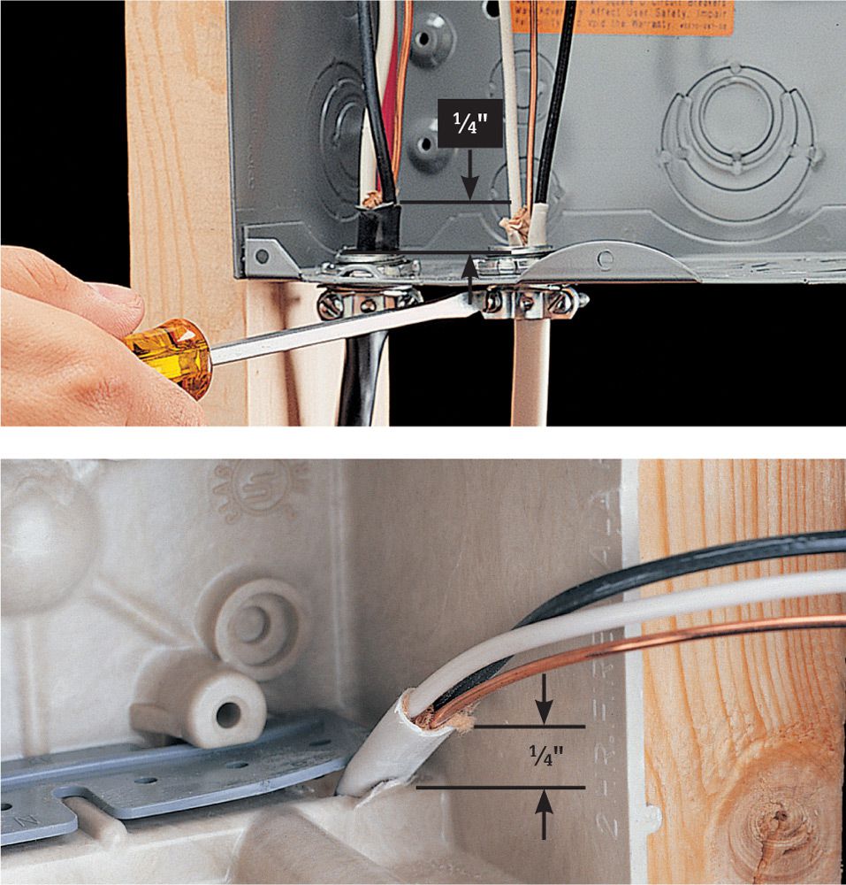
Variation: Different types of boxes have different clamping devices. Make sure cable sheathing extends 1/4" past the edge of the clamp to ensure that the cable is secure and that the wire won’t be damaged by the edges of the clamp. Clamp cable inside all boxes except single gang (2 1/4 x 4") boxes.
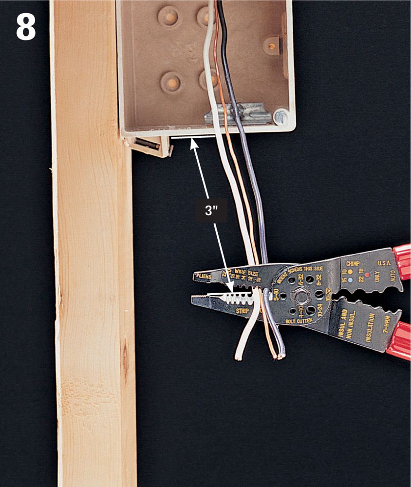
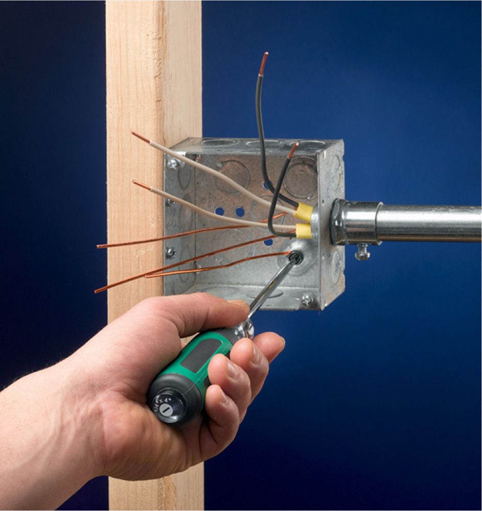
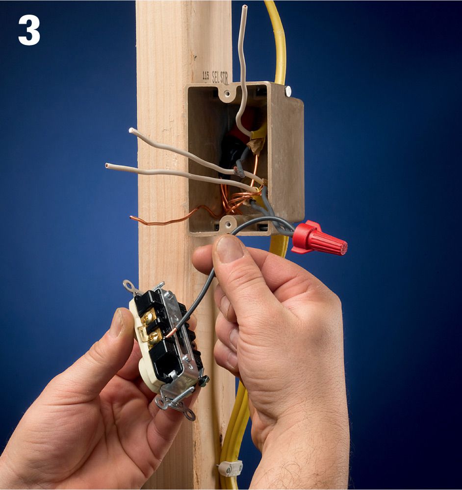
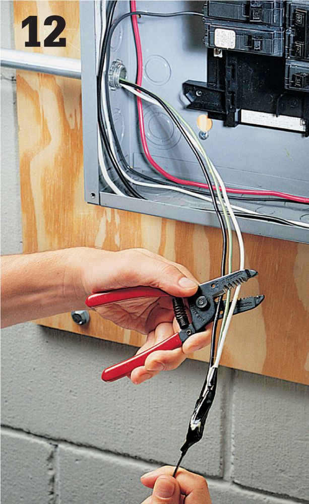
As each cable is installed in a box, clip back each wire so that at least 3" of workable wire extends past the front edge of the box.
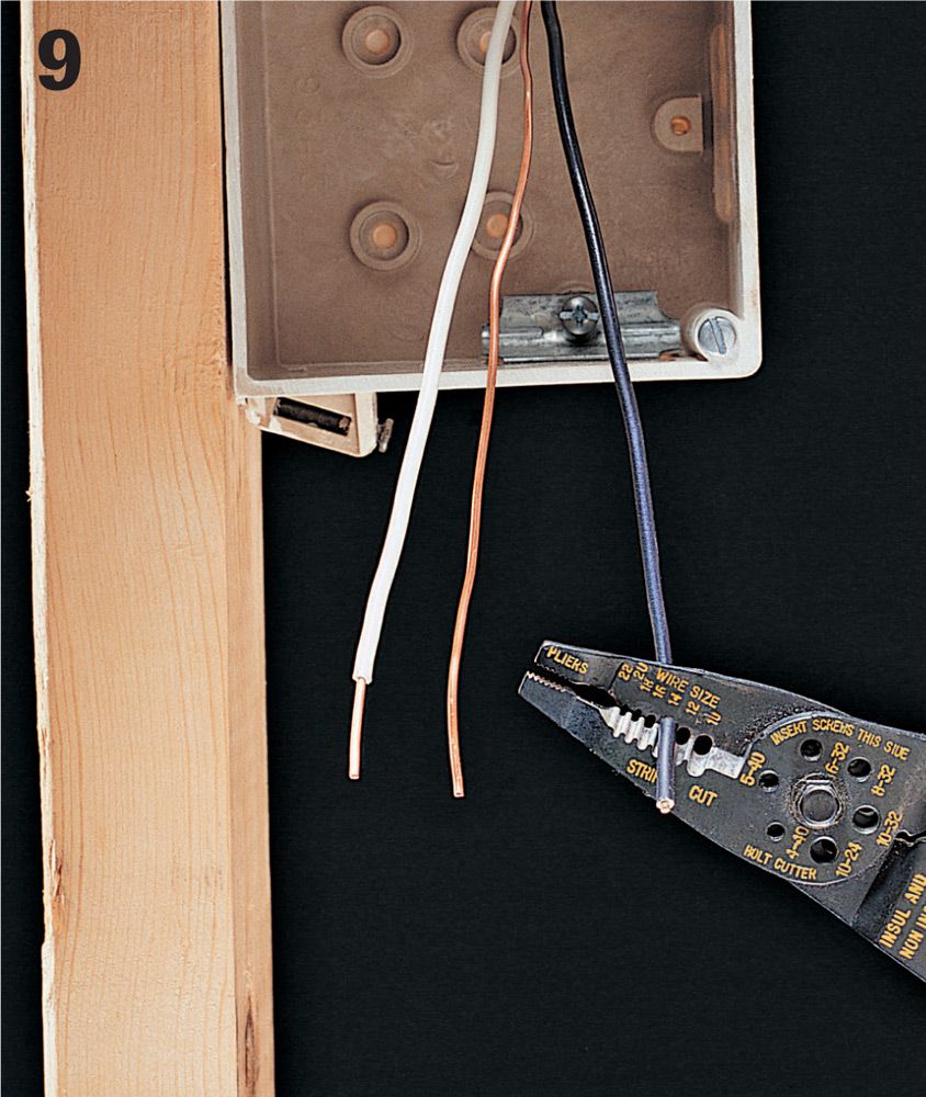
Strip 3/4" of insulation from each circuit wire in the box using a combination tool. Take care not to nick the copper.
Continue the circuit by running cable between each pair of electrical boxes, leaving an extra 1 ft. of cable at each end.
At metal boxes and recessed fixtures, open knockouts, and attach cables with cable clamps. From inside the fixture, strip away all but 1/4" of sheathing. Clip back wires so there is 8" of workable length, and then strip 3/4" of insulation from each wire.
For a surface-mounted fixture such as a baseboard heater or fluorescent light fixture, staple the cable to a stud near the fixture location, leaving plenty of excess cable. Mark the floor so the cable will be easy to find after the walls are finished.
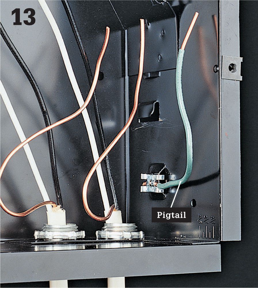
At each recessed fixture and metal electrical box, connect one end of a grounding pigtail to the metal frame using a grounding clip attached to the frame (shown above) or a green grounding screw.
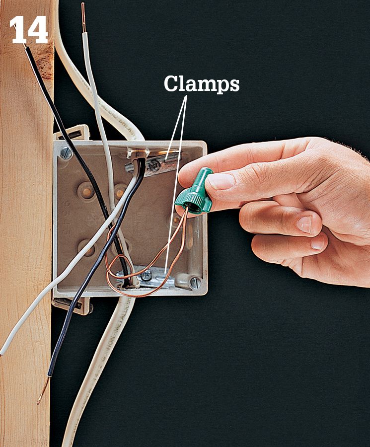
At each electrical box and recessed fixture, join grounding wires together with a wire connector. If the box has internal clamps, tighten the clamps over the cables.
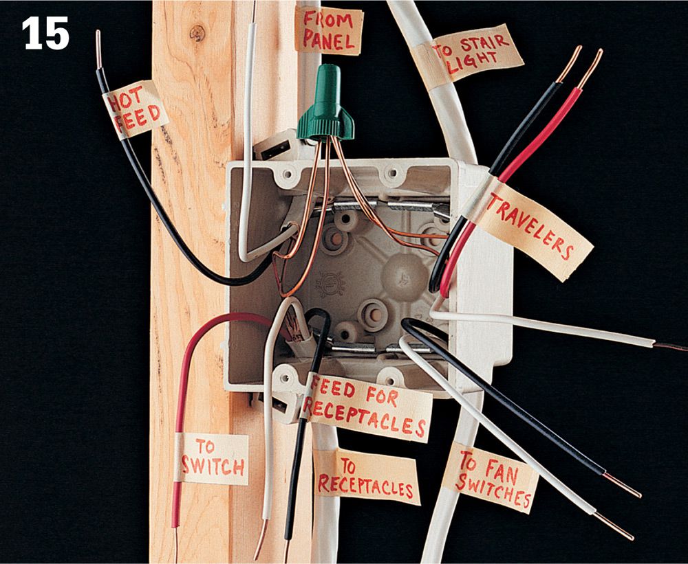
Label the cables entering each box to indicate their destinations. In boxes with complex wiring configurations, also tag the individual wires to make final hookups easier. After all cables are installed, your rough-in work is ready to be reviewed by the electrical inspector.
![]() How to Run NM Cable inside a Finished Wall
How to Run NM Cable inside a Finished Wall
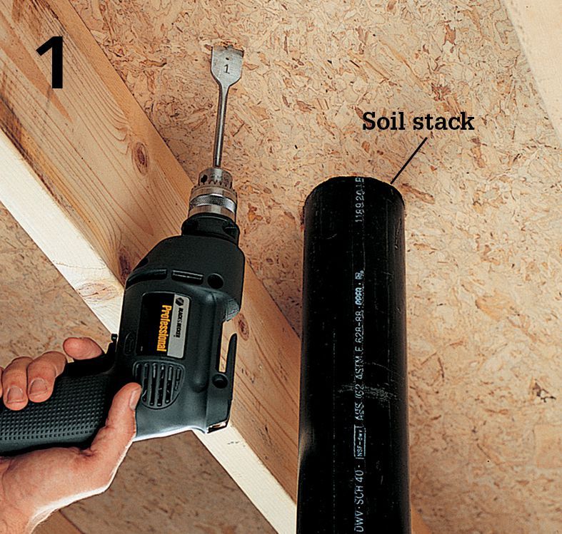
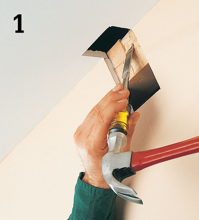
From the unfinished space below the finished wall, look for a reference point, such as a soil stack, plumbing pipes, or electrical cables, that indicates the location of the wall above. Choose a location for the new cable that does not interfere with existing utilities. Drill a 1" hole up into the stud cavity.
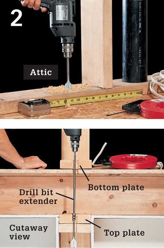
From the unfinished space above the finished wall, find the top of the stud cavity by measuring from the same fixed reference point used in step 1. Drill a 1" hole down through the top plate and into the stud cavity using a drill bit extender.
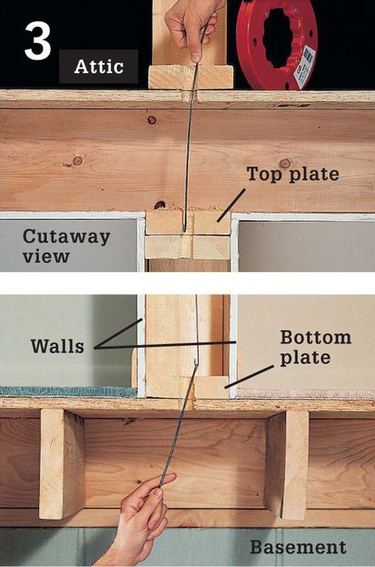
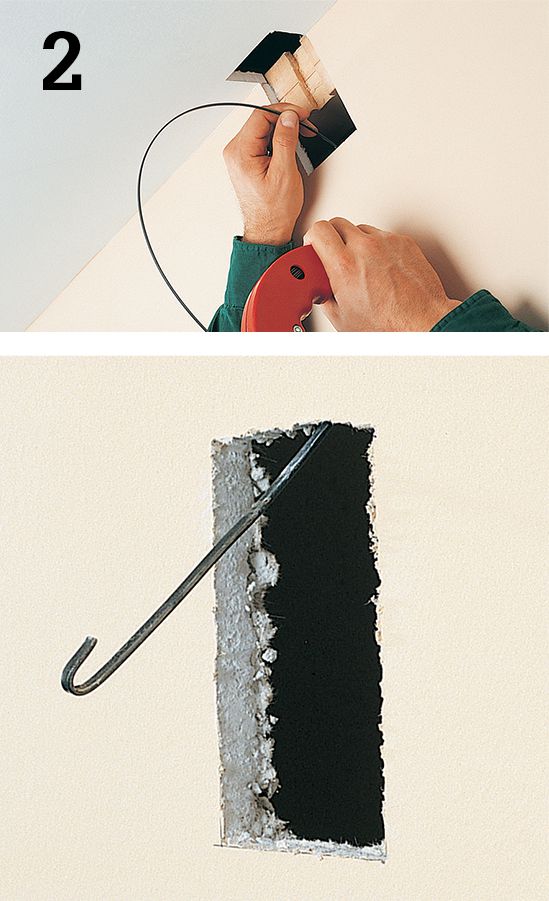
Extend a fish tape down through the top plate, twisting the tape until it reaches the bottom of the stud cavity. From the unfinished space below the wall, use a piece of stiff wire with a hook on one end to retrieve the fish tape through the drilled hole in the bottom plate.
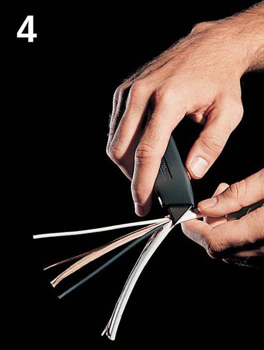
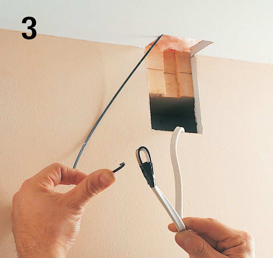
Trim back 2" of sheathing from the end of the NM cable, and then insert the wires through the loop at the tip of the fish tape.
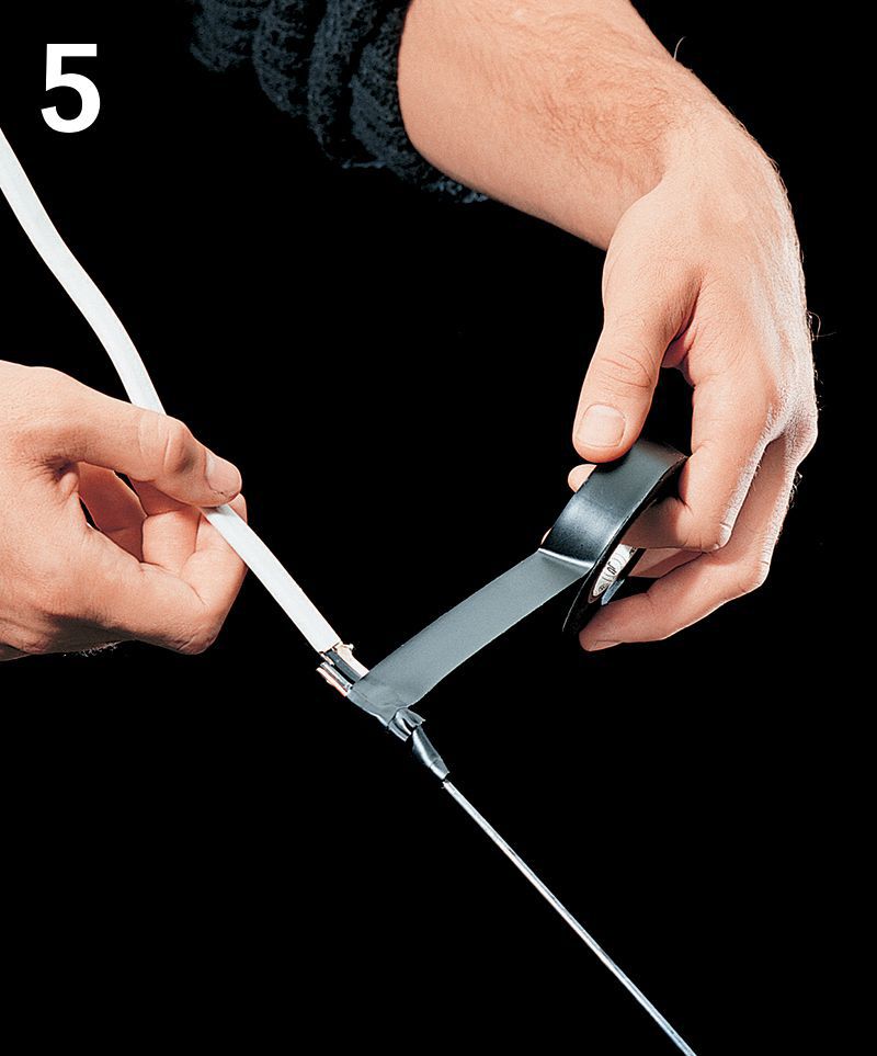
Bend the wires against the cable, and then use electrical tape to bind them tightly. Apply cable-pulling lubricant to the taped end of the fish tape.
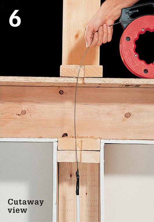
From above the finished wall, pull steadily on the fish tape to draw the cable up through the stud cavity. This job will be easier if you have a helper feed the cable from below as you pull.
![]() Running Cable inside Finished Walls
Running Cable inside Finished Walls
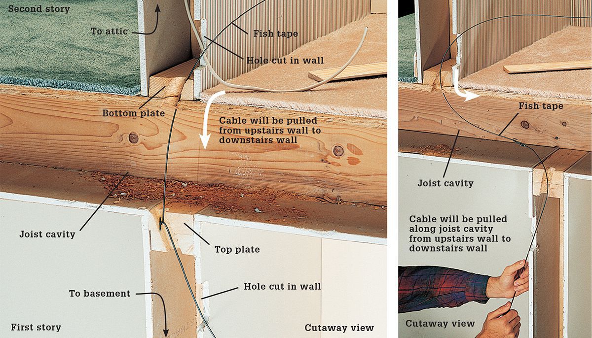
If there is no access space above and below a wall, cut openings in the finished walls to run a cable. This often occurs in two-story homes when a cable is extended from an upstairs wall to a downstairs wall. Cut small openings in the wall near the top and bottom plates, then drill an angled 1" hole through each plate. Extend a fish tape into the joist cavity between the walls and use it to pull the cable from one wall to the next. If the walls line up one over the other (left), you can retrieve the fish tape using a piece of stiff wire. If walls do not line up (right), use a second fish tape. After running the cable, repair the holes in the walls with patching plaster or wallboard scraps and taping compound.
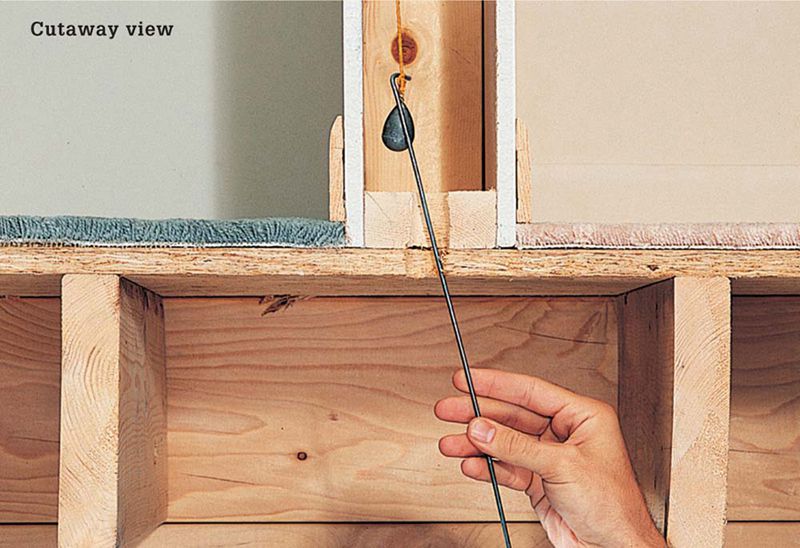
If you don’t have a fish tape, use a length of sturdy string and a lead weight or heavy washer. Drop the line into the stud cavity from above, and then use a piece of stiff wire to hook the line from below.
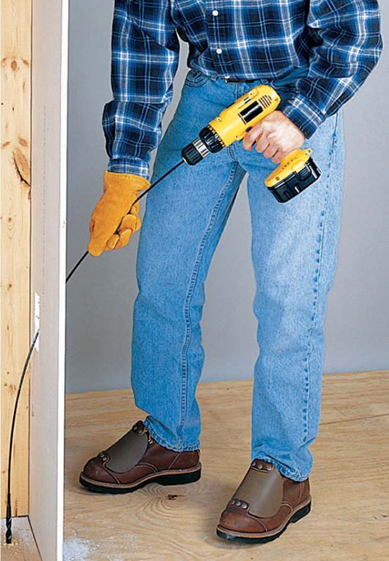
Use a flexible drill bit, also called a bell-hanger’s bit, to bore holes through framing in finished walls.
![]() How to Install NM Cable in Finished Ceilings
How to Install NM Cable in Finished Ceilings
If you don’t have access to a ceiling from above, you can run cable for a new ceiling fixture from an existing receptacle in the room up the wall and into the ceiling without disturbing much of the ceiling. Be sure not to tap into a restricted circuit such as the kitchen counter top and bathroom receptacles. To begin, run cable from the receptacle to the stud channel that aligns with the ceiling joists on which you want to install a fixture. Be sure to plan a location for the new switch. Remove short strips of drywall from the wall and ceiling. Make a notch in the center of the top. Use a fish tape to pull the new cable up through the wall cavity and the notch in top plates. Next use the fish tape to pull the cable through the ceiling to the fixture hole. When you are finished pulling the cable, protect the notch with metal nail guards. After having your work inspected, replace the drywall and install the fixture and switch.
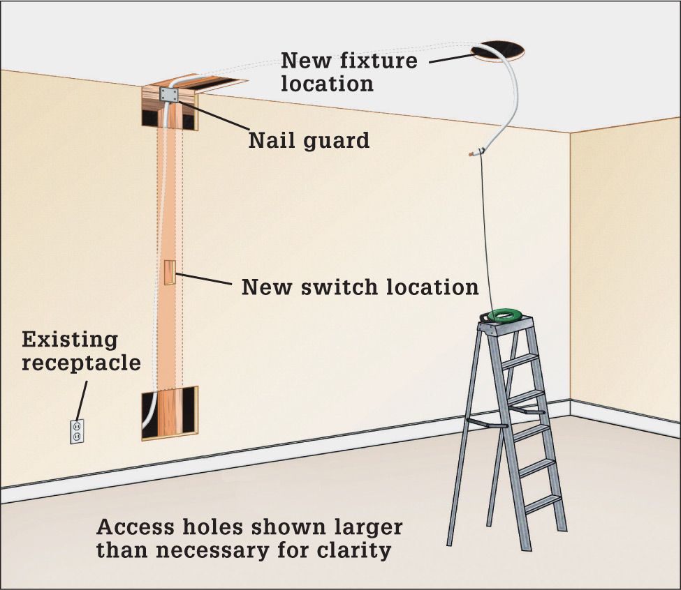
Plan a route for running cable between electrical boxes (see illustration above). Remove drywall on the wall and ceiling surface. Where cable must cross framing members, cut a small access opening in the wall and ceiling surface; then cut a notch into the framing with a wood chisel.
Fish a cable from the existing receptacle location up to the notch at the top of the wall. Protect the notch with a metal nail stop.
Fish the cable through the ceiling to the location of the new ceiling fixture.
![]() Conduit
Conduit
All individual wires (such as THHN/THWN) must be installed in conduit or in thinner material called tubing. Cables and wires that are subject to physical damage must be installed in conduit or some types of tubing to protect them. Whether a location is subject to physical damage depends on the judgment of the electrical inspector. Cables that are exposed and are within the reach of an adult and most cables installed outside are often considered subject to physical damage. Other exposed locations may also qualify.
The interior of conduit and tubing installed outside is considered a wet area. Don’t install NM cable inside conduit installed outside. Use UF cable instead or pull individual wires rated for wet area use. Conduit and tubing installed outdoors must be rated for exterior use.
![]() Electrical Bonding of Metal Conduit
Electrical Bonding of Metal Conduit
Install a green insulated grounding wire for any circuit that runs through metal conduit. Although code allows the metal conduit to serve as the grounding conductor, most electricians install a green insulated wire as a more dependable means of grounding the system. The grounding wires must be connected to metal boxes with a pigtail and grounding screw (left) or grounding clip (right).
![]() Metal Conduit
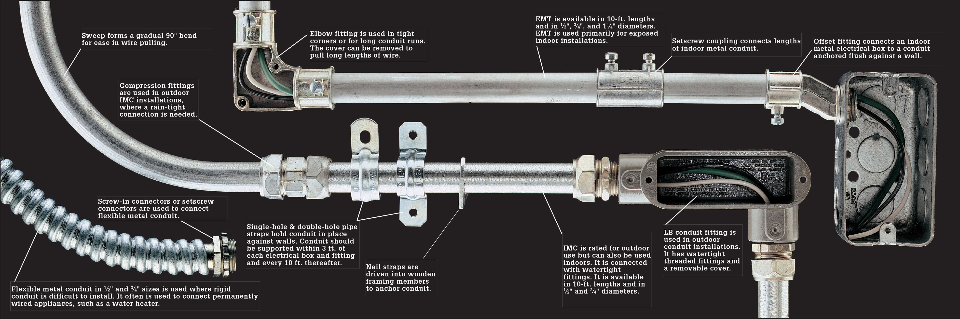
Metal Conduit
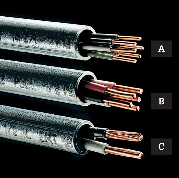
EMT 1/2" in diameter can hold up to twelve 14-gauge or nine 12-gauge THHN/THWN wires (A), five 10-gauge wires (B), or three 8-gauge wires (C). Use 3/4" conduit for greater fill capacity.
![]() Fill Capacity
Fill Capacity

EMT is lightweight and easy to install. IMC has thicker galvanized walls and is a good choice for exposed outdoor use. Rigid metal conduit provides the greatest protection for wires, but it is more expensive and requires threaded fittings. EMT is the preferred metal material for home use.
![]() Plastic Conduit
Plastic Conduit
Plastic PVC conduit and tubing are allowed by many local codes. It is assembled with solvent glue and PVC fittings that resemble those for metal conduit. When wiring with PVC conduit and tubing, always run a green grounding wire. Use material approved for use in electrical applications. Do not use PVC plumbing pipes.
![]() Working with Conduit
Working with Conduit
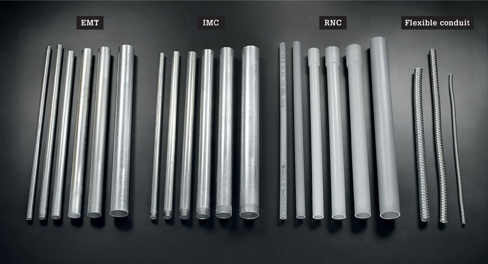
Conduit types used most in homes are EMT (electrical metallic tubing), IMC (intermediate metallic conduit), RNC (rigid nonmetallic conduit), and flexible metal conduit. The most common diameters by far are 1/2" and 3/4", but larger sizes are stocked at most building centers.
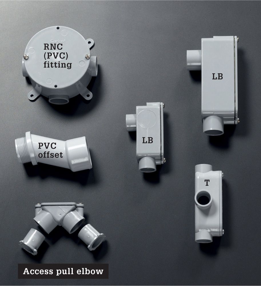
Nonmetallic conduit fittings typically are solvent-welded to nonmetallic conduit, as opposed to metal conduit, which can be threaded and screwed into threaded fittings or attached with setscrews or compression fittings.
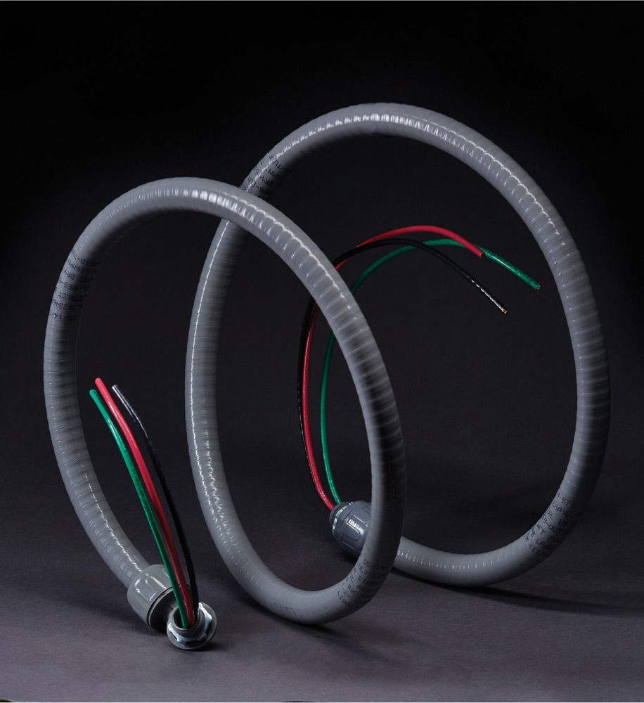
Liquid-tight flexible conduit (LFC) is used in outdoor applications, especially around pools and water features and at irrigation controllers.
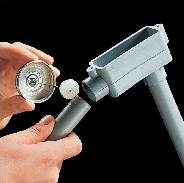
![]() How to Make Nonmetallic Conduit Connections
How to Make Nonmetallic Conduit Connections
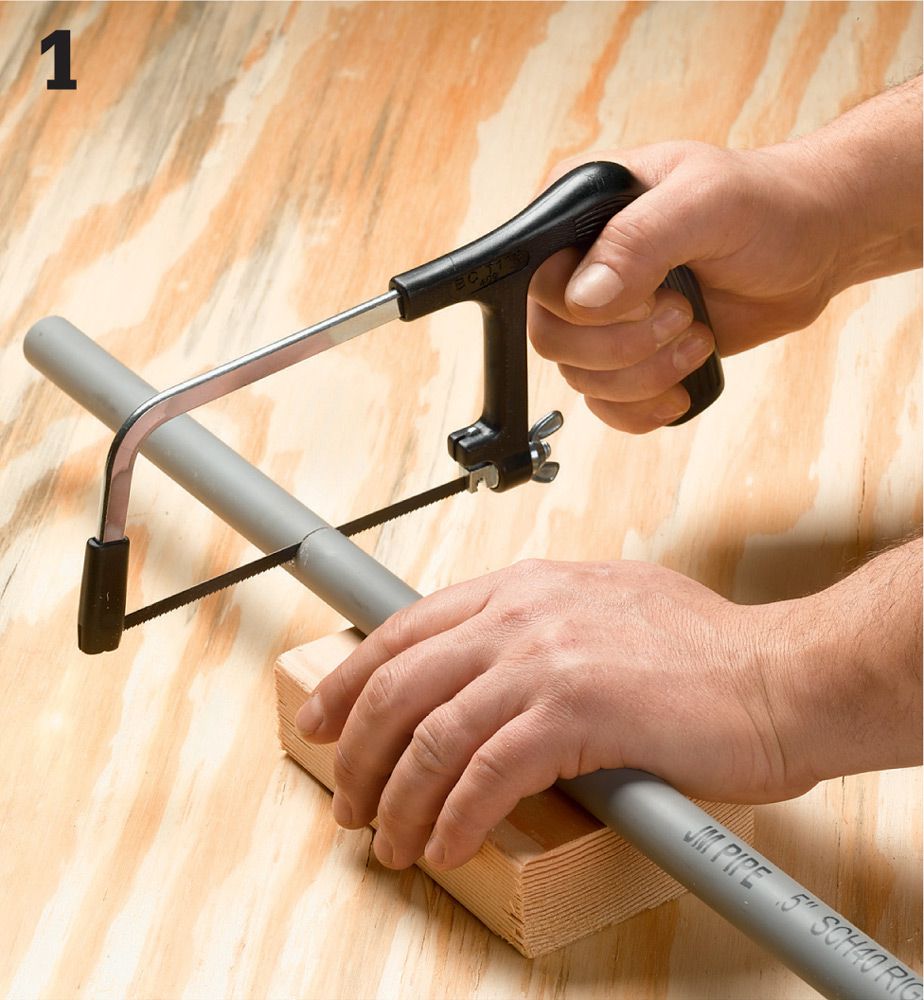
Cut the rigid nonmetallic conduit (RNC) to length with a fine-tooth saw, such as a hacksaw. For larger diameter (1 1/2" and above), use a power miter box with a fine-tooth or plastic cutting blade.
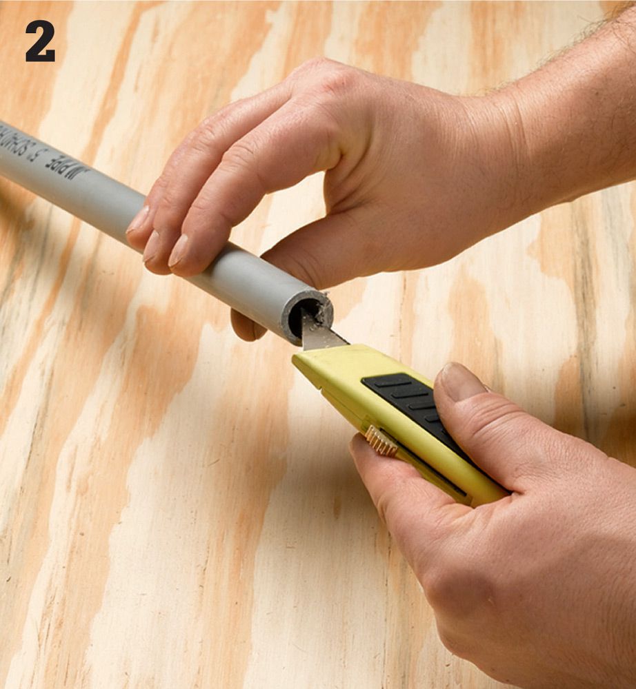
Deburr the cut edges with a utility knife or fine sandpaper such as emery paper. Wipe the cut ends with a dry rag. Also wipe the coupling or fitting to clean it.
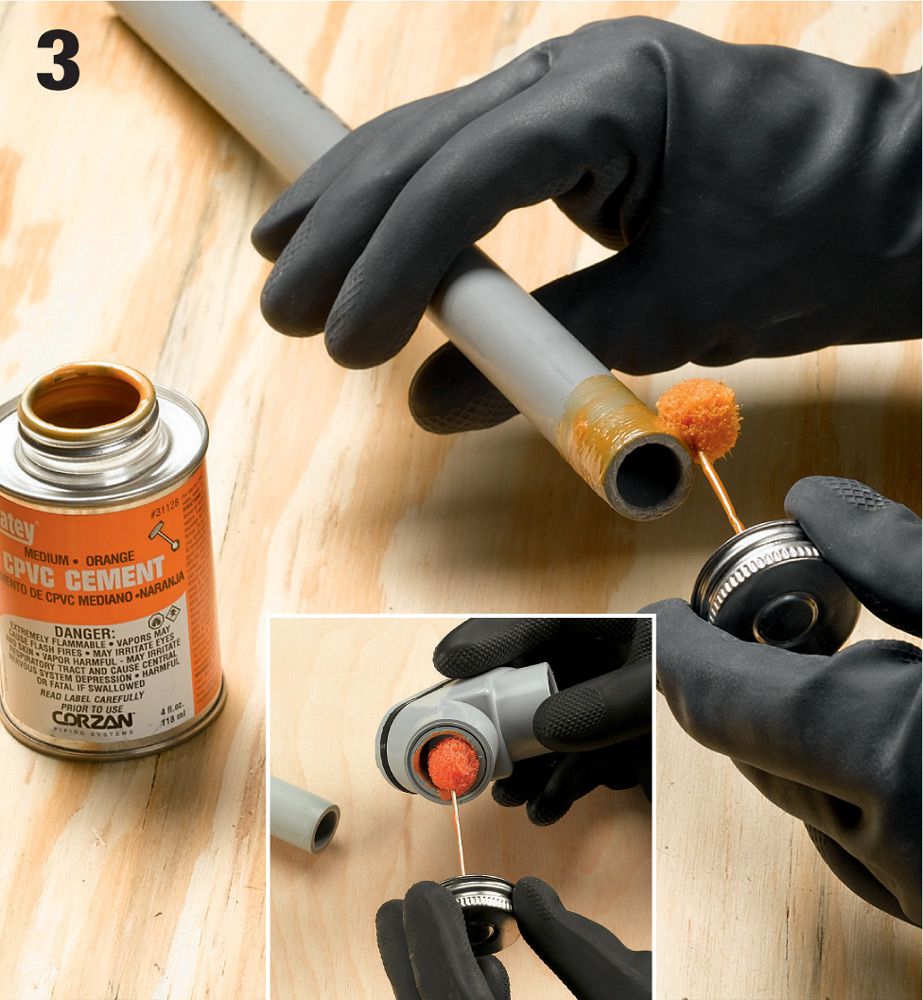
Apply a coat of PVC cement to the end of the conduit and to the inside walls of the coupling (inset). Wear latex gloves to protect your hands. The cement should be applied past the point on the conduit where it enters the fitting or coupling.
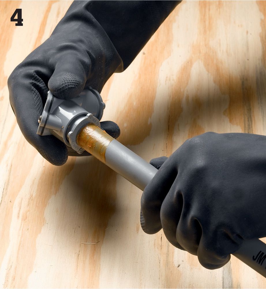
Insert the conduit into the fitting or coupling and spin it a quarter turn to help spread the cement. Allow the joint to set undisturbed for 10 minutes.
![]() How to Install Conduit & Wires on a Concrete Wall
How to Install Conduit & Wires on a Concrete Wall
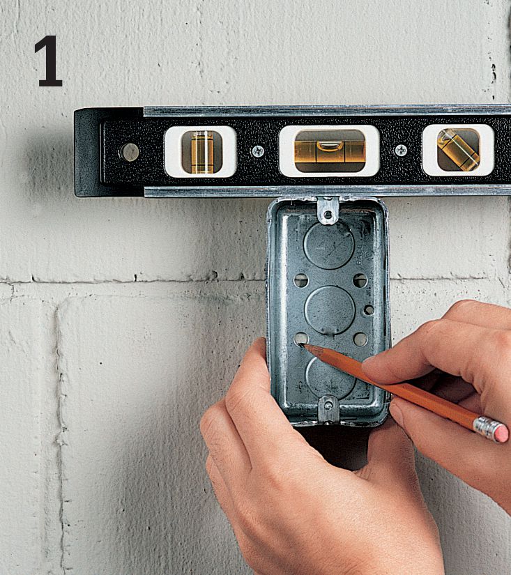
Measure from the floor to position electrical boxes on the wall, and mark location for mounting screws. Boxes for receptacles in an unfinished basement or other damp areas are mounted at least 2 ft. from the floor. Laundry receptacles usually are mounted at 48".
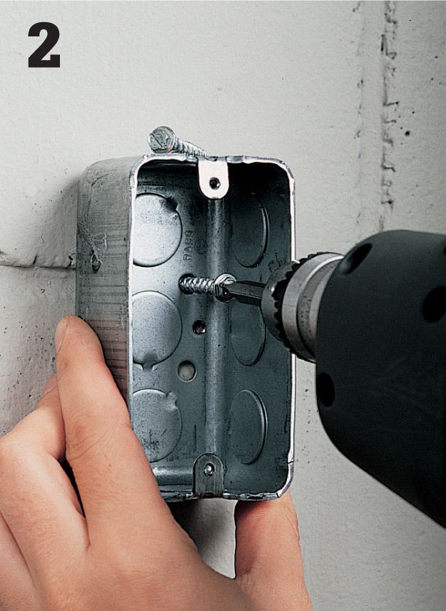
Drill pilot holes with a masonry bit, then mount the box against a masonry wall with masonry anchors, or use masonry anchors and panhead screws.
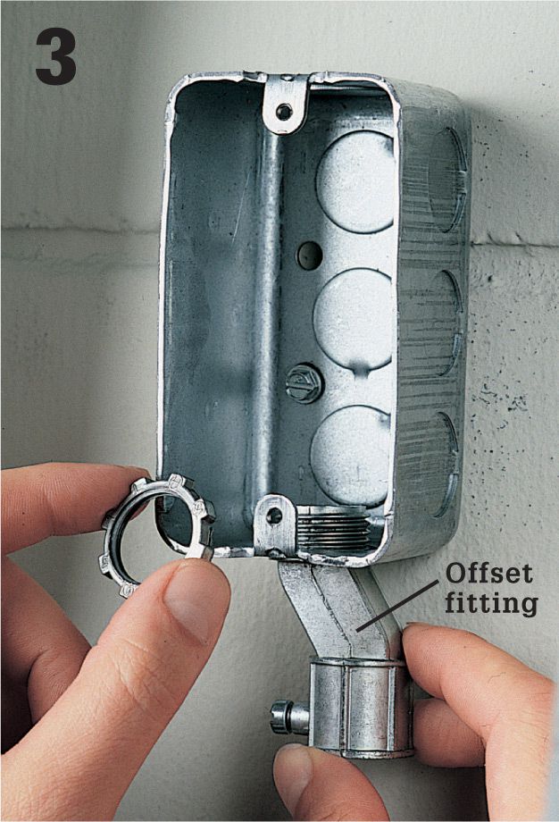
Open one knockout for each length of conduit that will be attached to the box. Attach an offset fitting to each knockout using a locknut.
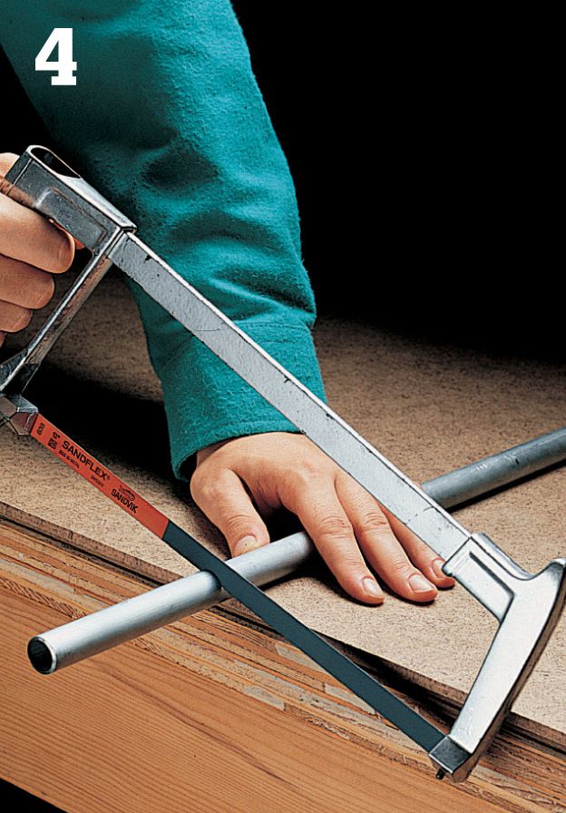
Measure the first length of conduit and cut it with a hacksaw. Remove any rough inside edges with a pipe reamer or a round file. Attach the conduit to the offset fitting on the box, and tighten the setscrew.
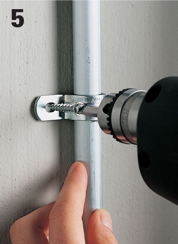
Anchor the conduit against the wall with pipe straps and masonry anchors. Conduit should be anchored within 3 ft. of each box and fitting and every 10 ft. thereafter.
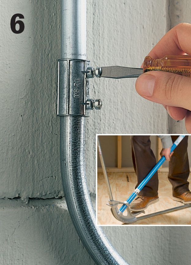
Make conduit bends by attaching a sweep fitting using a setscrew fitting or compression fitting. Continue attaching additional lengths. You can also use a conduit bender (inset) to make your own sweeps and bends.
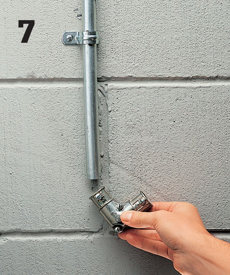
Use an elbow fitting in conduit runs that have many bends or in runs that require very long wires. The cover on the elbow fitting can be removed to make it easier to extend a fish tape and pull wires.
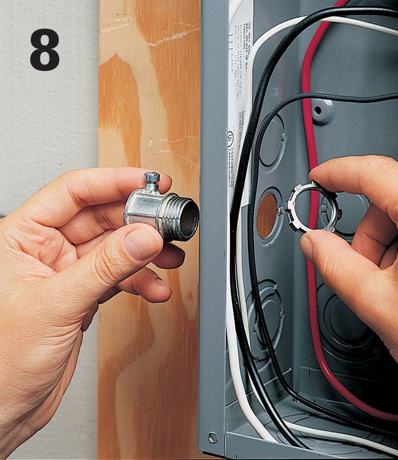
At the panel, turn the power off, and then remove the cover and test for power. Open a knockout in the panel, attach a setscrew fitting, and install the last length of conduit.
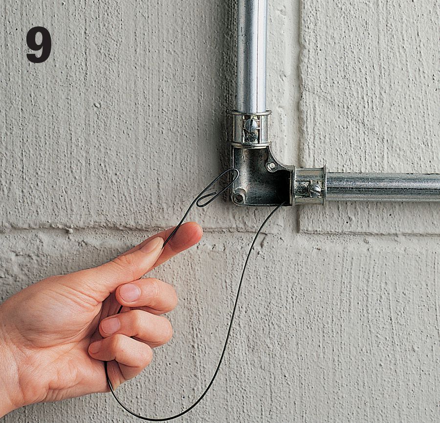
Unwind the fish tape and extend it through the conduit from the circuit breaker panel outward. Remove the cover on an elbow fitting when extending the fish tape around tight corners.
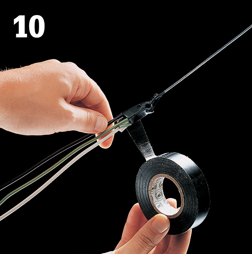
Trim back 2" of outer insulation from the end of the wires, and then insert the wires through the loop at the tip of the fish tape.
Retrieve the wires through the conduit by pulling on the fish tape with steady pressure. Note: Use extreme care when using a metal fish tape inside a circuit breaker panel, even when the power is turned off.
Clip off the taped ends of the wires. Leave at least 2 ft. of wire at the service panel and 3" extending beyond the front edges at each electrical box.
![]() Surface-Mounted Wiring
Surface-Mounted Wiring
Surface-mounted wiring is a network of electrical circuits that run through small, decorative tubes that function much like conduit. The systems include matching elbows, T-connectors, and various other fittings and boxes that are also surface-mounted. The main advantage to a surface-mounted wiring system is that you can add a new fixture onto a circuit without cutting into your walls.
Although they are extremely convenient and can even contribute to a room’s decor when used thoughtfully, surface-mounted wiring systems do have some limitations. They are not allowed for some specific applications (damp areas such as bathrooms, for example) in many areas, so check with the local building authorities before beginning a project. And the boxes that house the switches and receptacles tend to be very shallow and more difficult to work with than ordinary boxes.
In some cases, you may choose to run an entirely new circuit with surface-mounted wiring components (at least starting at the point where the branch circuit wire reaches the room from the service panel). But more often, a surface-mounted wiring circuit ties into an existing receptacle or switch. If you are tying into a standard switch box for power, make sure the load wire for the new surface-mounted wiring circuit is connected to the hot wire in the switch box before it is connected to the switch (otherwise, the surface-mounted wiring circuit will be off whenever the switch is off).
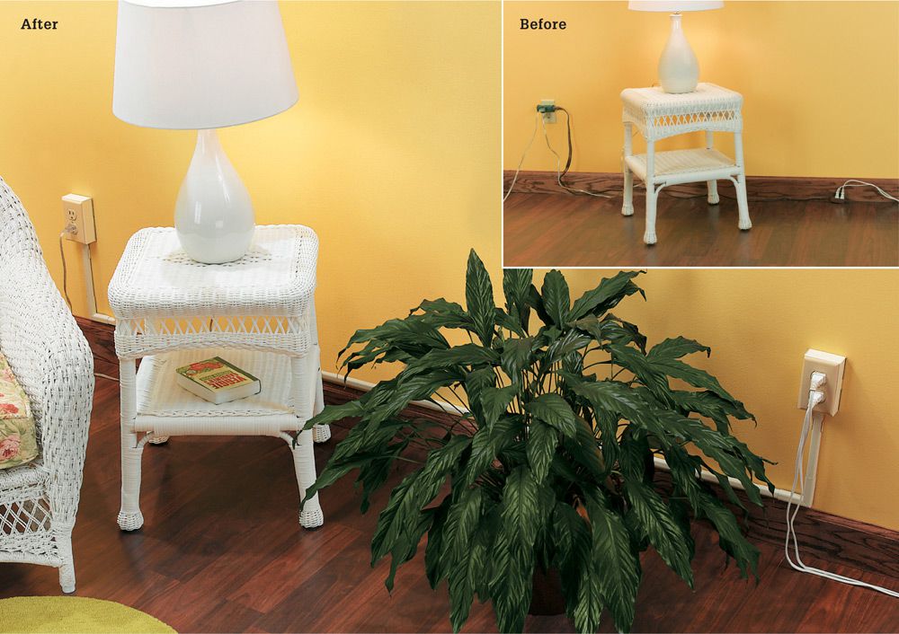
Surface-mounted wiring circuits are networks of cable channels and electrical boxes that allow you to run new wiring without cutting into walls. If you have a room with too much demand on a single receptacle (inset), installing a surface-mounted circuit with one or more new outlets is a good solution.
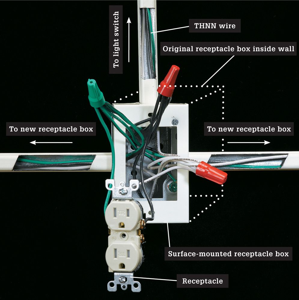
A surface-mounted receptacle box is mounted directly to the original electrical box (usually for a receptacle) and raceway tracks are attached to it. The tracks house THNN wires that run from the new box to new receptacles and light switches.
![]() Parts of a Surface-Mounted System
Parts of a Surface-Mounted System
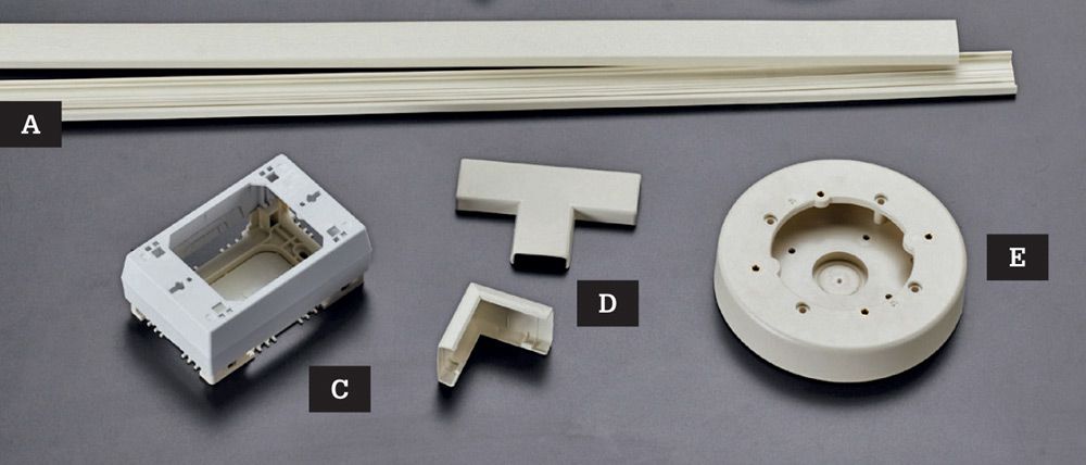
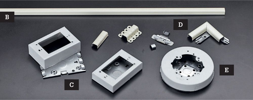
Surface-mounted wiring systems employ two-part tracks that are mounted directly to the wall surface to house cable. Lighter-duty plastic raceways (A), used frequently in office buildings, are made of snap-together plastic components. For home wiring, look for a heavier metal-component system (B). Both systems include box extenders for tying in to a receptacle (C), elbows, T-connectors, and couplings (D), and boxes for fixtures (E).
![]() How to Install Surface-Mounted Wiring
How to Install Surface-Mounted Wiring
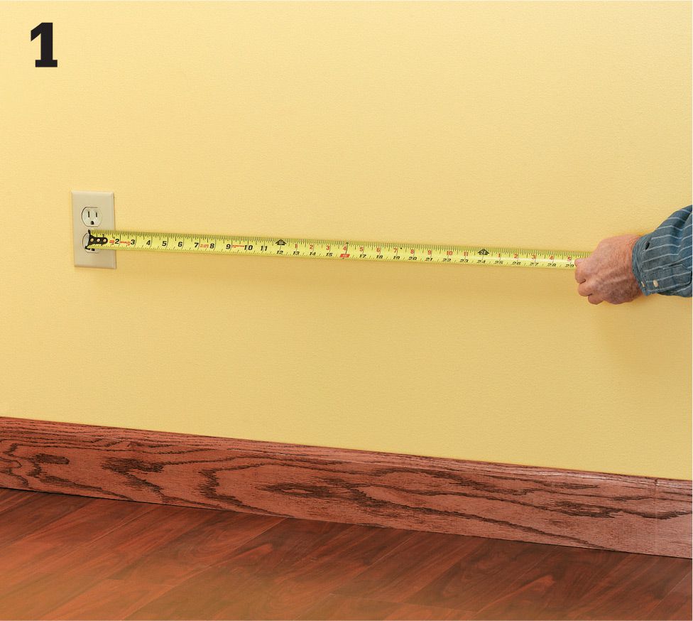
Confirm that the circuit you want to expand will support a new receptacle or light (see pages 136 to 141). Measure from the power source to the new receptacle or switch. Purchase enough raceway to cover this distance plus about 10 percent extra. Buy a surface-mounted starter box, new receptacle box, and fittings for your project (the raceway product packaging usually provides guidance for shopping).
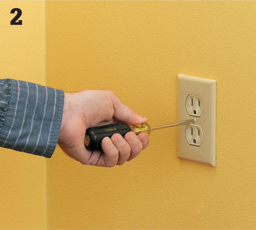
Shut off the power to the outlet. Remove the cover plate from the receptacle by unscrewing the screw that holds the plate to the electrical box. Set the screws and the plate aside. With the cover plate off, you will be able to see the receptacle and the electrical box it is attached to. If your existing receptacle is not a tamper-resistant model replace it with one (see page 109).
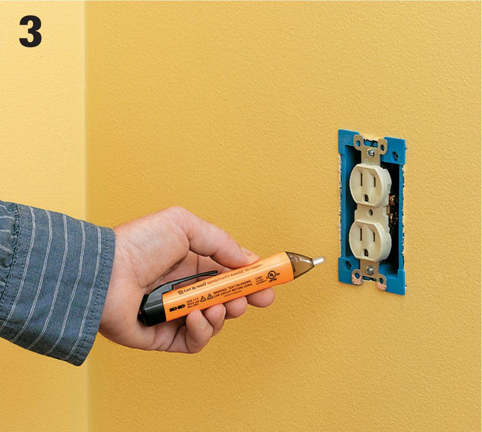
Before you remove the old receptacle, use a touchless circuit tester to double-check that the circuit is dead. Hold your voltage sensor’s probe within 1/2" of the wires on each side of the receptacle. If the sensor beeps or lights up, then the receptacle is still live, and you’ll need to trip the correct breaker to disconnect power to the receptacle. If the sensor does not beep or light up, the receptacle is dead and you can proceed safely.
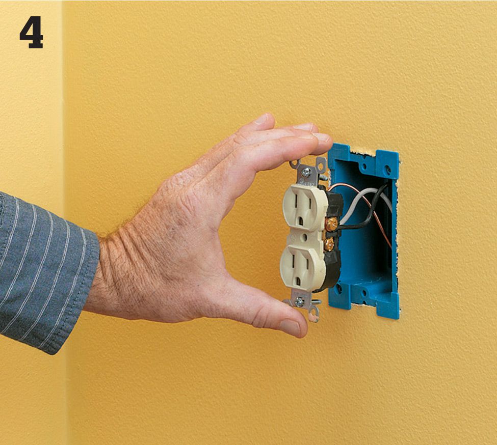
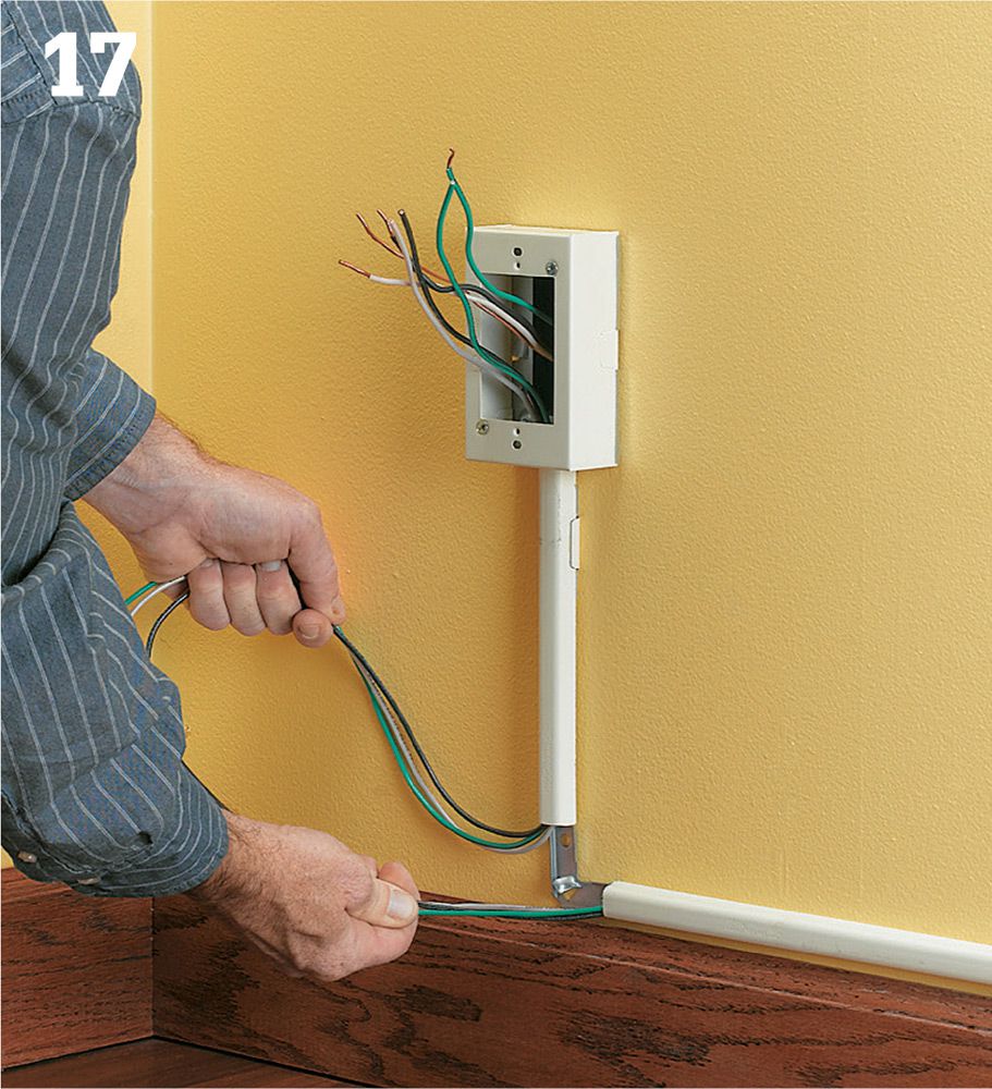
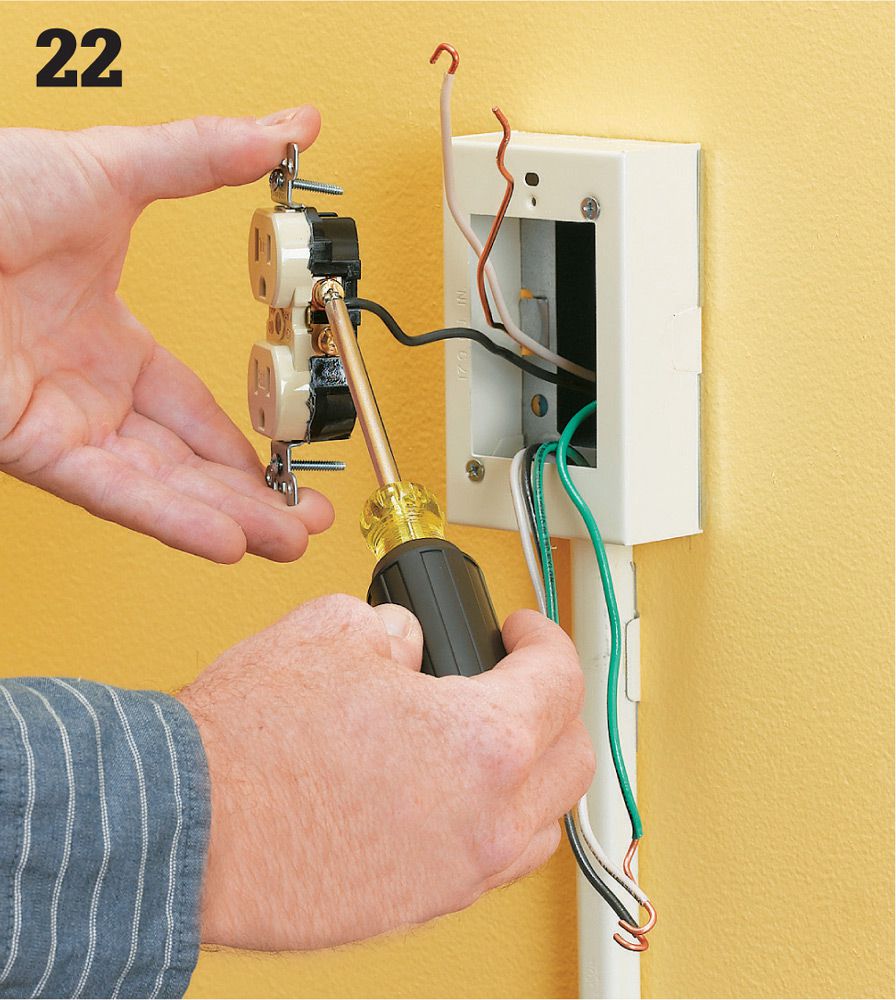
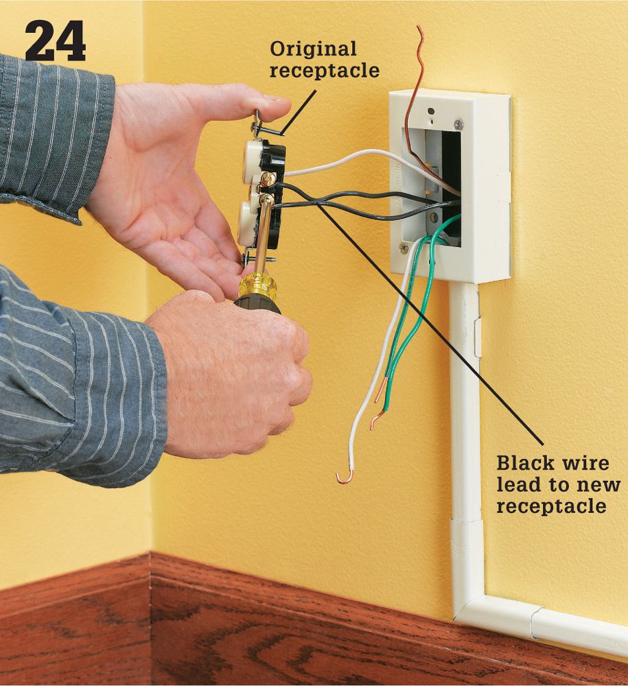
Remove the receptacle from the box by unscrewing the two long screws that hold it to the box. Once the screws are out, gently pull the receptacle away from the box. Depending on how your receptacle has been wired, you may find two insulated wires and a bare copper wire or four insulated wires and a bare wire. Detach these wires and set the receptacle aside.
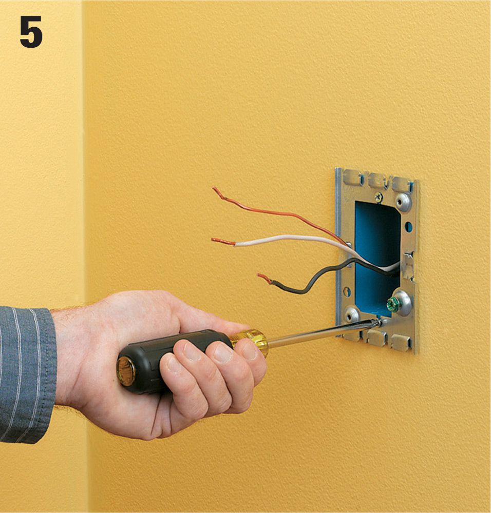
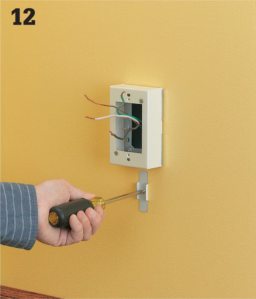
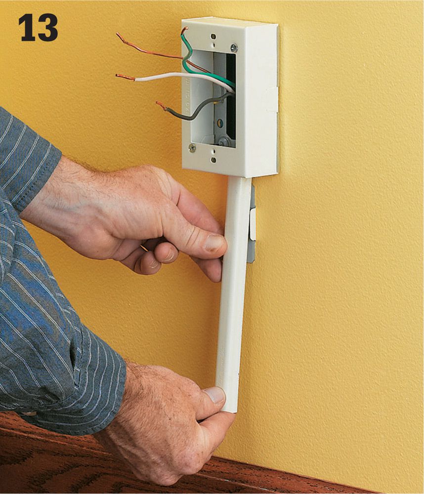
Your starter box includes a box and a mounting plate with an open back. Pull all the wires you just disconnected through the opening. Screw the mounting plate to the existing receptacle box with the included mounting screws. The predrilled ground screw hole should contain a #10/32 grounding screw.
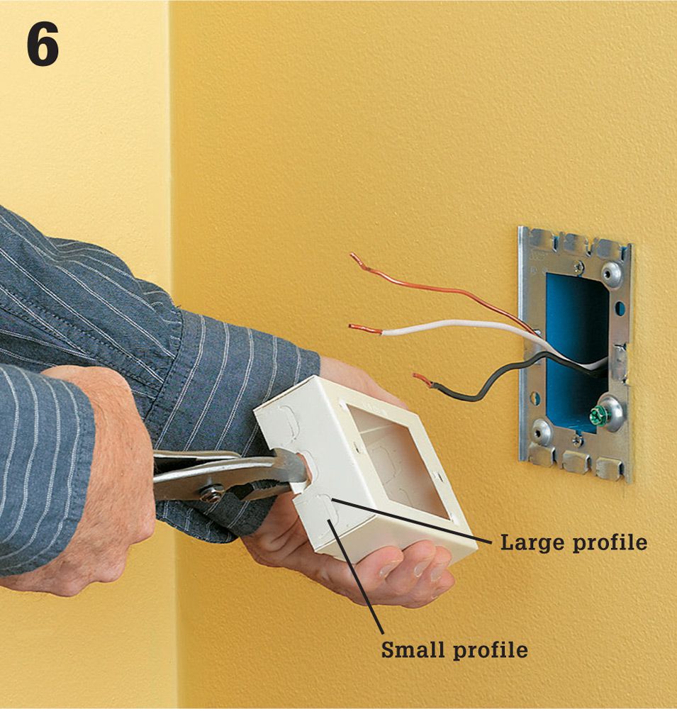
Remove a knockout from the starter box to create an opening for the track using pliers. Often the prepunched knockouts have two profile options—make sure the knockout you remove matches the profile of your track.
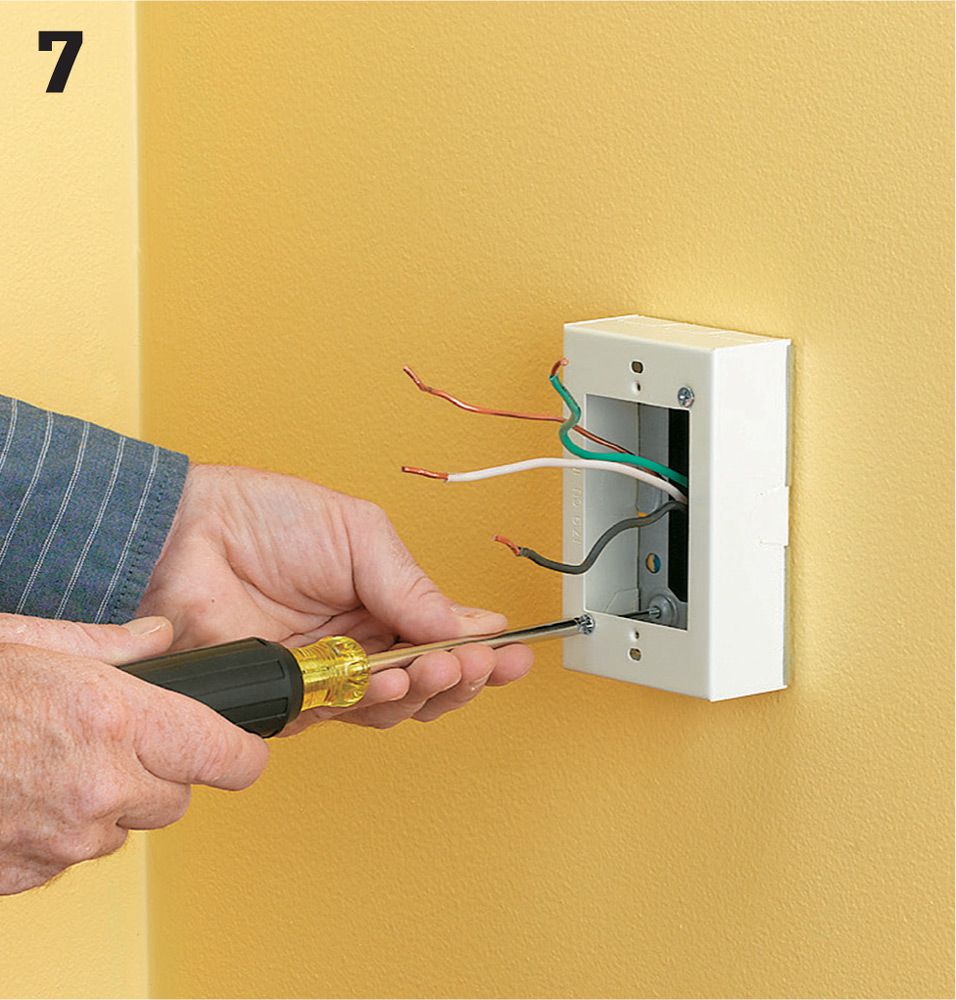
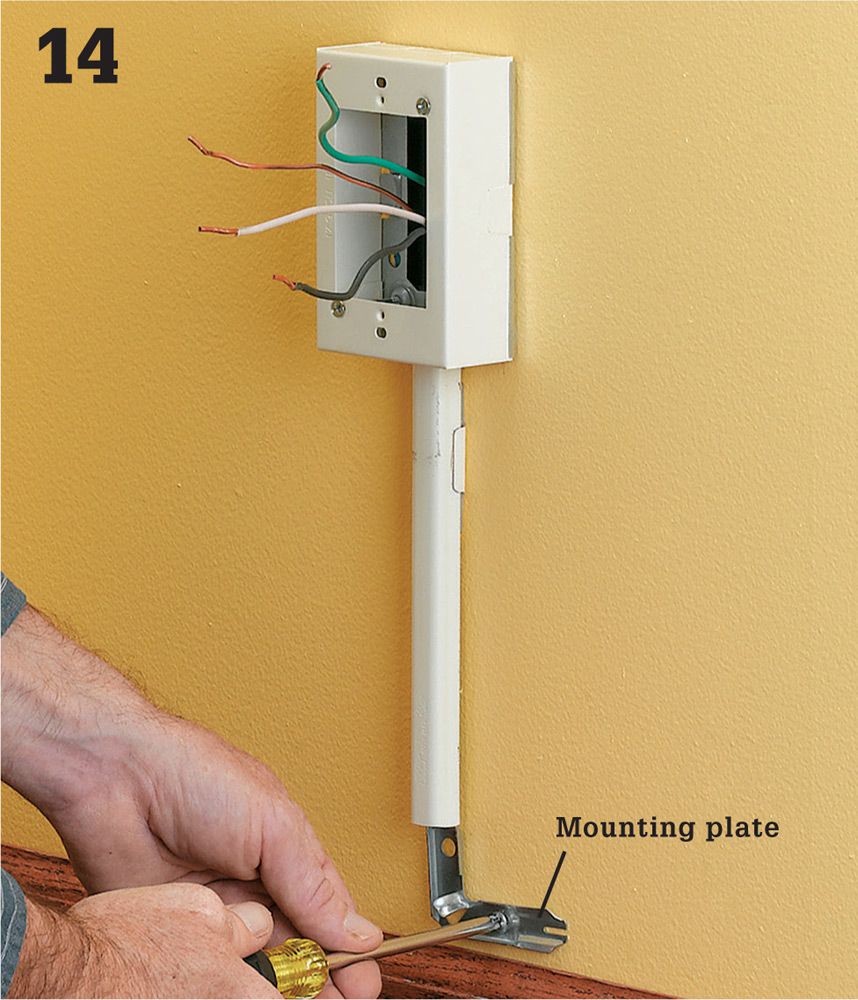
Hold the box portion of the starter box over the mounting plate on the existing receptacle. Drive the mounting screws through the holes in the box and into the threaded openings in the mounting plate.
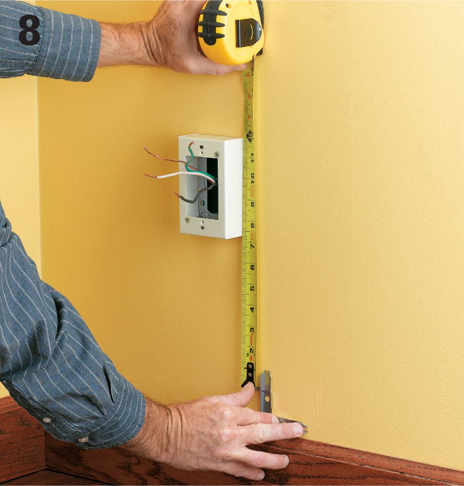
Set the mounting bracket for an elbow connector 1/4" above the baseboard (having the track run along the baseboard edge looks better than running it in a straight line out of the starter box). Measure from the knockout in the starter box to the top of the bracket and cut a piece of track 1/2" longer than this measurement.
Tool Tip ![]()
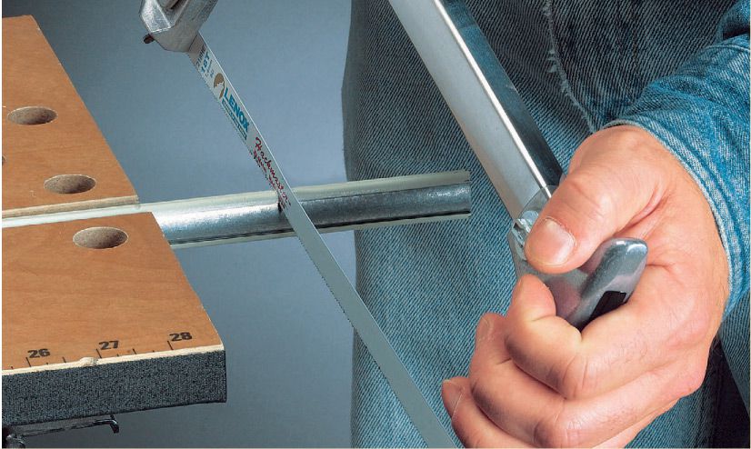
Metal raceway can be cut like metal conduit. Secure the track or conduit in a vise or clamping work support, and cut with a hacksaw. For best results, use long, slow strokes and don’t bear down too hard on the saw. Once the cut is made, file the metal burrs smooth with a metal file.
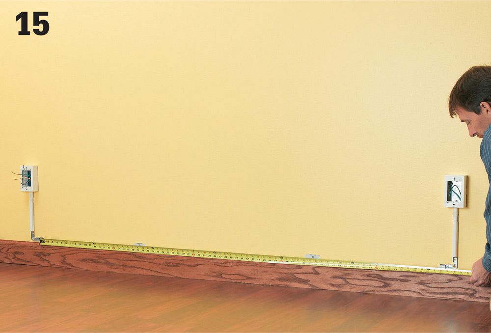
At the new receptacle location, transfer the height of the top of the starter box and mark a reference line. If possible, locate the box so at least one screw hole in the mounting plate falls over a wall stud. Position the mounting plate for the receptacle box up against the reference line and secure it with screws driven through the mounting plate holes. If the plate is not located over a wall stud, use wall anchors (see below right).
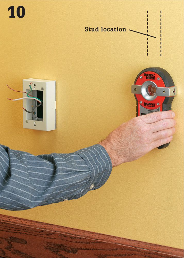
Use a stud finder to locate and mark all of the wall framing members between the old receptacle and the new one. There is usually a 1 1/2"-wide stud every 16" behind the wall.
Wall Anchors ![]()
Here’s how to install wall anchors. Mark screw locations on the wall, and then drill a narrow guide hole for the screw anchor. Drive the anchor into the guide holes until the flange is flush with the wall surface.
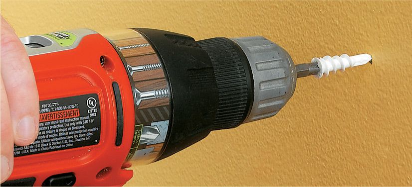
Ideally anything you attach to a drywall wall should be anchored at a wall stud location. Of course, in the real world this often is not possible. You’ll find many kinds of wall anchors for sale at the local hardware store. Some work better than others. The common tapered plastic sleeves that are driven into guide holes will work for lighter duty, but they don’t grip the wall well enough to secure surface mounted wiring components. For this, use coarse-threaded, screw-in anchors. You simply mark the location for your mounting screws and drive the sleeve directly into the wall with a drill/driver: no pilot hole required.
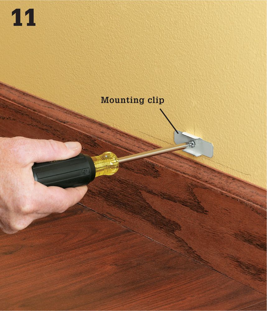
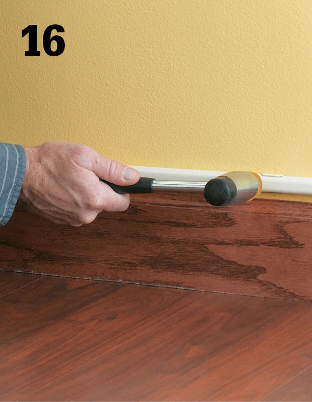
At stud locations mark a reference line 1/4" above the top of the baseboard. Attach mounting clips for the track at these marks.
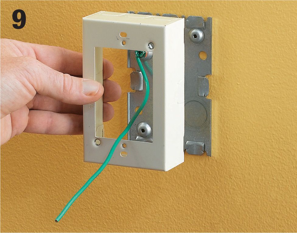
Install mounting clips 1/2" or so below the knockouts on both the starter box and the new receptacle box. The clips should line up with the knockouts.
At the starter box slide one end of the short piece of raceway into the knockout so that about 1/8" extends into the box. Snap the raceway into the clip below the knockout. Repeat this same procedure at the new receptacle box.
The elbow piece will have two parts, a mounting plate and a cap. Install the mounting plates directly below the pieces of track entering the receptacle boxes.
Measure and cut the long piece of track that fits between the two receptacles. Measure the distance between the ends of the horizontal parts of the elbows, and cut a length of raceway to that length. Be sure to measure all the way to the base of the clip, not just to the tips of the connector points.
Snap the long piece of track into the mounting clips. Line up one end of the track with the end of an elbow and tap the track with a rubber mallet until it is snapped into all of the clips. At the new receptacle location, snake the ends of the wires up through the vertical piece of track and into the new receptacle box. There should be about 3" of wire coming out at each box.
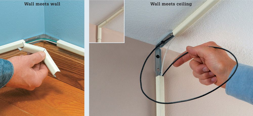
Tip: Making corners with raceway ![]()
What if I need to go around a corner? Use corner pieces to guide around corners. Corners are available for inside or outside corners and consist of a mounting plate and a cap piece. Inside corners may be used at wall/ceiling junctures.
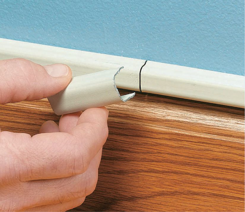
Tip: Splicing raceway ![]()
What if I need a piece of track that’s longer than the longest piece available at the hardware store (usually 5 ft.)? You can use straight connector pieces to join two lengths of track. Much like an elbow piece, they have a mounting plate and a cover that snaps over the wiring.
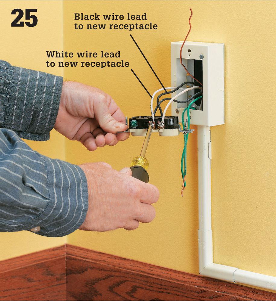
Cut black, white, and green THNN wire about 2 ft. longer than the length of each wiring run. Snake the end of each wire into the starter box, through the knockout, and into the vertical track. Then snake the wire all the way through the long piece of track so about 12 to 16" comes out on each end.
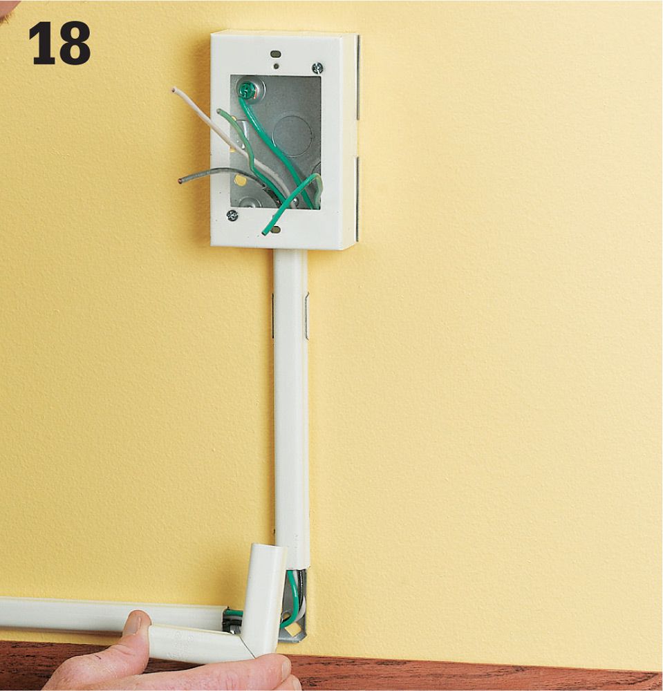
Finish the track installation by snapping the elbow cover pieces into place over the mounting plates, one at the starter box and another at the new receptacle location. You may need to rap the plate with a rubber mallet to get enough force to snap it on. Make sure all of the wire fits completely within the cover pieces.
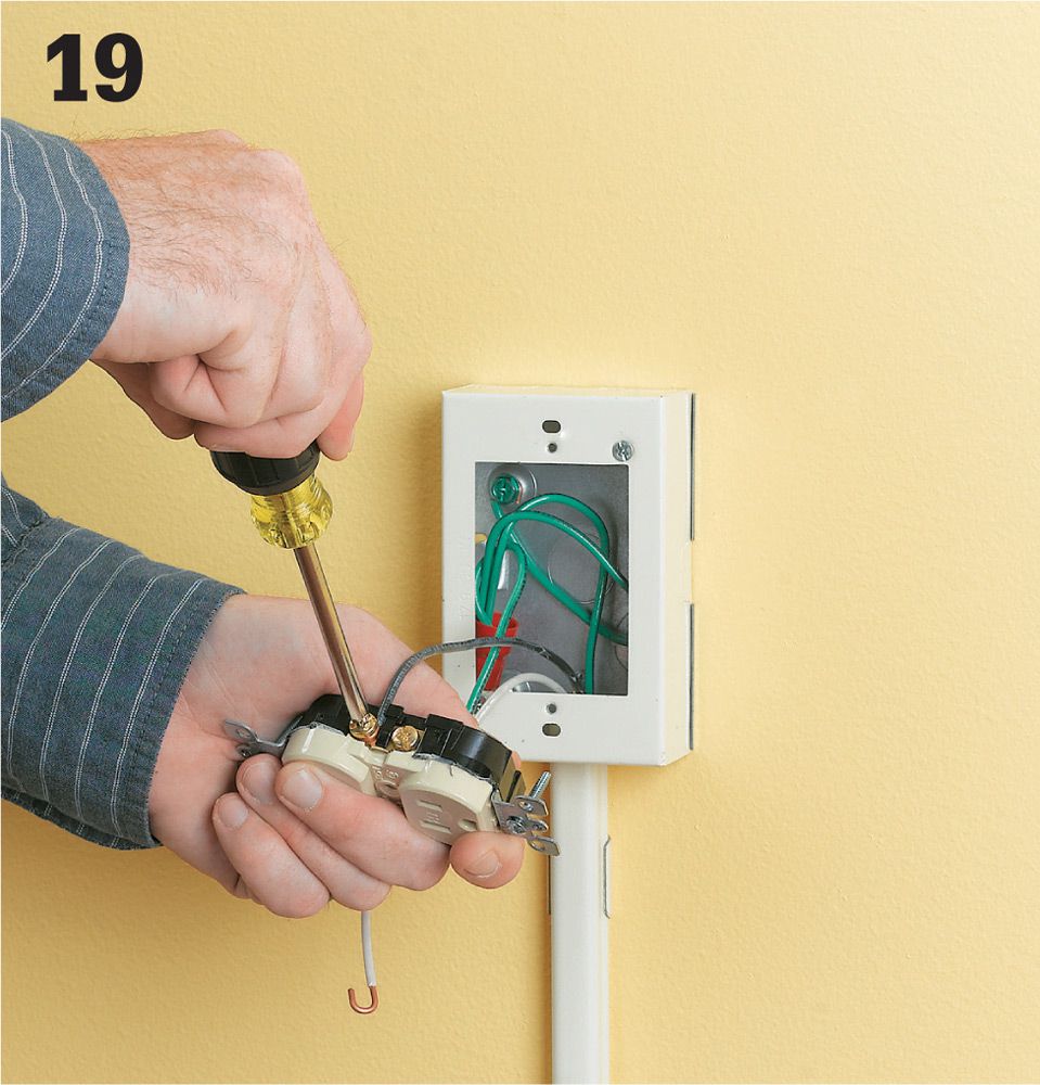
Now you can wire the receptacles. Begin at the new receptacle location. Wrap the end of the black wire around the bottom gold screw on the side of the receptacle. Tighten the screw so it’s snug.
Wrap the end of the white wire around the silver screw opposite the gold one you just used. Tighten the screw so it’s snug. Connect the green wire to the green-colored screw on the bottom of the receptacle.
Once the connections are made, gently tuck the wires and the receptacle into the box so the holes in the top and bottom of the receptacle align with the holes in the box. Use a screwdriver to drive the two long mounting screws that hold the receptacle to the box. Attach the cover plate.
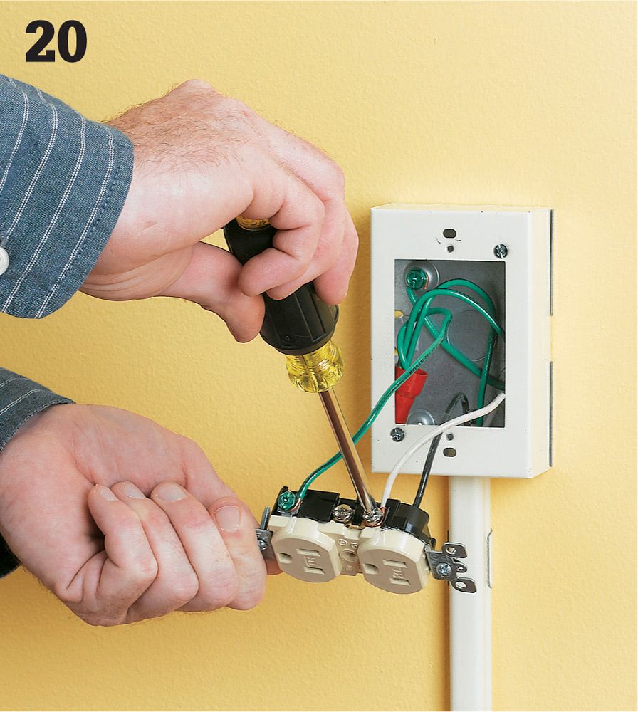
Now you can install the new receptacle at the starter box. First make sure the power is still off with your touchless circuit tester. Wrap the end of the black wire around the top gold screw on the side of the receptacle. Tighten the screw.

Wrap the end of the white wire around the silver screw opposite the gold one you just used. Tighten the screw.
Connect the old receptacle to the new one. Take the black wire that goes into the raceway and wrap the end of the wire around the bottom gold screw on the side of the receptacle. Tighten the screw.
Wrap the end of the old white wire around the silver screw opposite the copper one you just used. Tighten the screw.
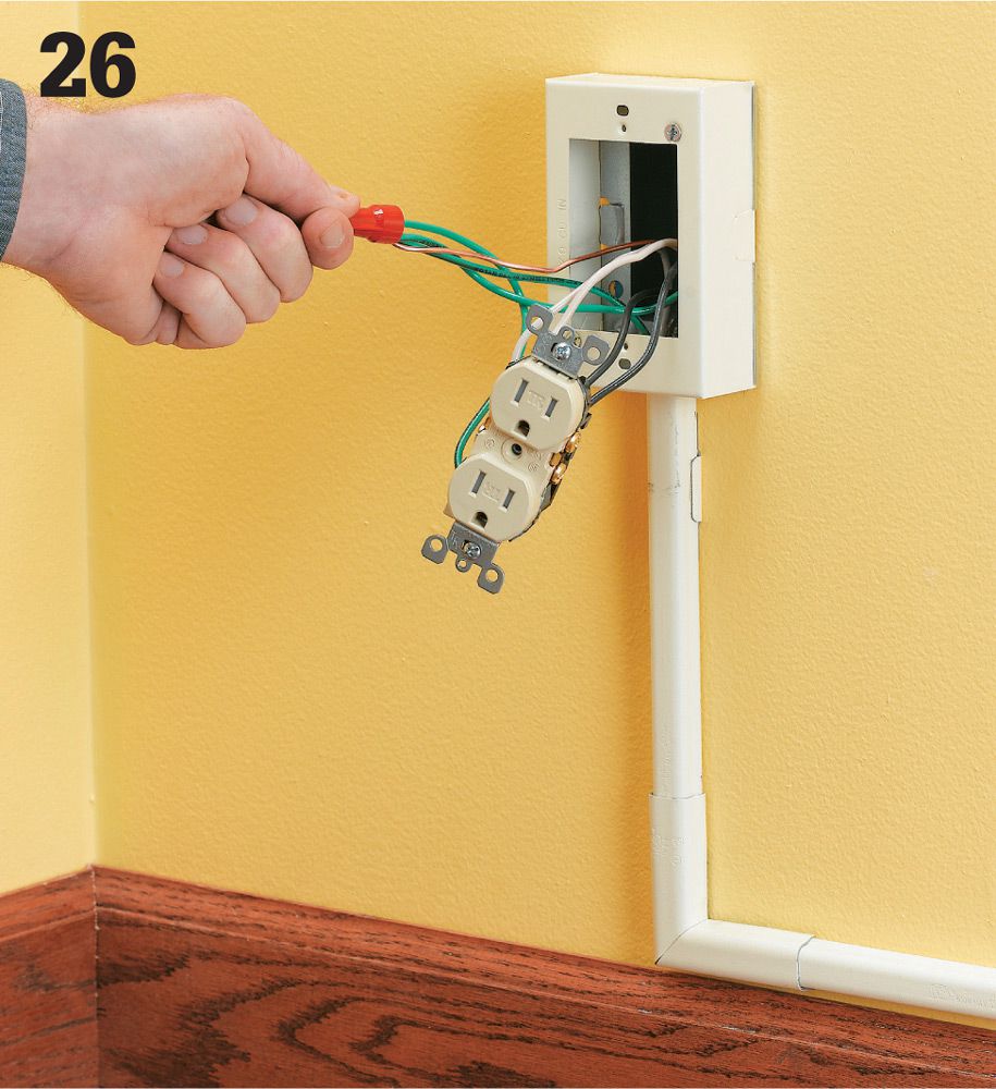
Finally, cut a piece of green wire at least 6" long and strip 3/4" from both ends (this is called a pigtail wire). Join one end of the pigtail with the ends of the bare and green wires in the box using a wire connector. Wrap the other end of the pigtail around the green screw on the receptacle.
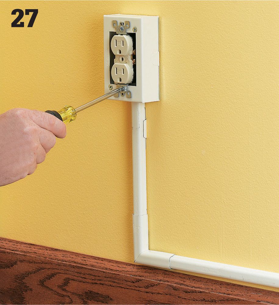
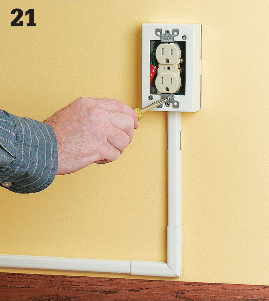
Once the connections are made, tuck the wires and the receptacle into the box so the holes in the top and bottom of the receptacle align with the holes in the box. Use a screwdriver to drive the two long mounting screws that hold the receptacle to the box. Install the cover plate. You can now restore the power and test your new receptacle.