The Complete Guide to Wiring, Updated 6th Edition: Current with 2014-2017 Electrical Codes - Black & Decker, Cool Springs Press (2014)
Chapter 1. Working Safely with Wiring
The only way you can possibly manage home wiring projects safely is to understand how electricity works and how it is delivered from the street to the outlets in your home.
The most essential quality to appreciate about electricity is that the typical amounts that flow through the wires in your home can be fatal if you contact it directly. Sources estimate that up to 1,000 people are electrocuted accidentally in the U.S. every year. In addition, as many as 500 die in fires from electrical causes. Home wiring can be a very satisfying task for do-it-yourselfers, but if you don’t know what you’re doing or are in any way uncomfortable with the idea of working around electricity, do not attempt it.
This chapter explains the fundamental principles behind the electrical circuits that run through our homes. It also includes some basic tips for working safely with wiring, and it introduces you to the essential tools you’ll need for the job. The beginner should consider it mandatory reading. Even if you have a good grasp of electrical principles, take some time to review the material. A refresher course is always useful.
In this chapter:
![]() How Electricity Works
How Electricity Works
![]() Glossary of Electrical Terms
Glossary of Electrical Terms
![]() Understanding Electrical Circuits
Understanding Electrical Circuits
![]() Grounding & Polarization
Grounding & Polarization
![]() Home Wiring Tools
Home Wiring Tools
![]() Wiring Safety
Wiring Safety
![]() How Electricity Works
How Electricity Works
Ahousehold electrical system can be compared with a home’s plumbing system. Electrical current flows in wires in much the same way that water flows inside pipes. Both electricity and water enter the home, are distributed throughout the house, do their “work,” and exit.
In plumbing, water first flows through the pressurized water supply system. In electricity, current first flows along hot wires. Current flowing along hot wires also is pressurized. Electrical pressure is called voltage.
Large supply pipes can carry a greater volume of water than small pipes. Likewise, large electrical wires carry more current than small wires. This electrical current-carrying capacity of wires is called ampacity.
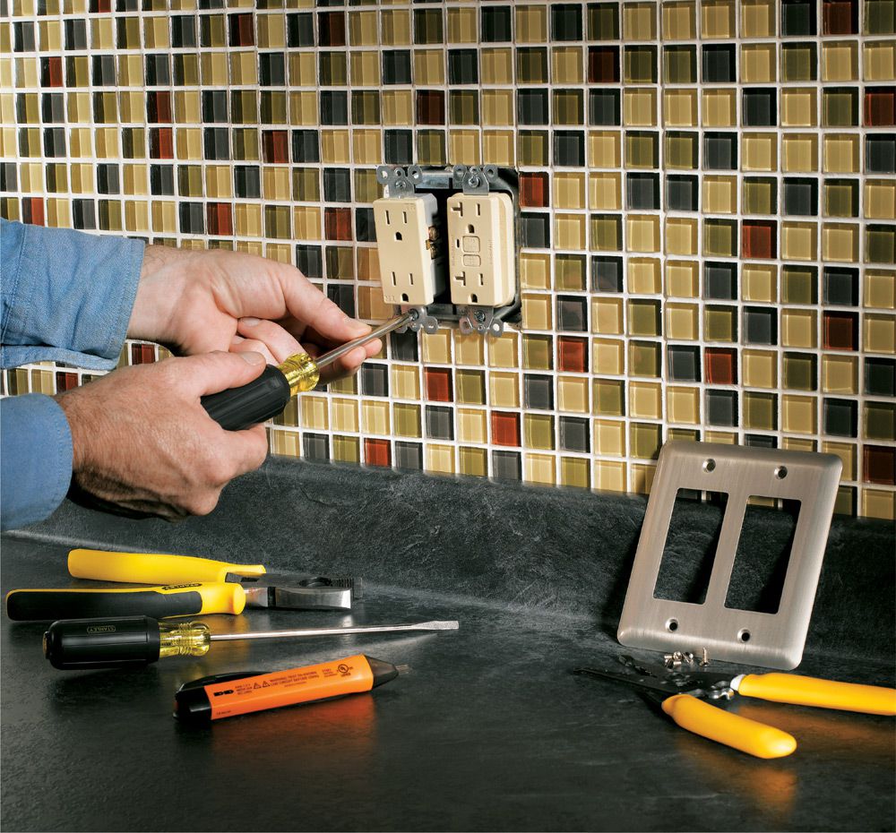
Water is made available for use through the faucets, spigots, and showerheads in a home. Electricity is made available through receptacles, switches, and fixtures.
Water finally leaves the home through a drain system, which is not pressurized. Similarly, electrical current flows back through neutral wires. The current in neutral wires is not pressurized and is at zero voltage.
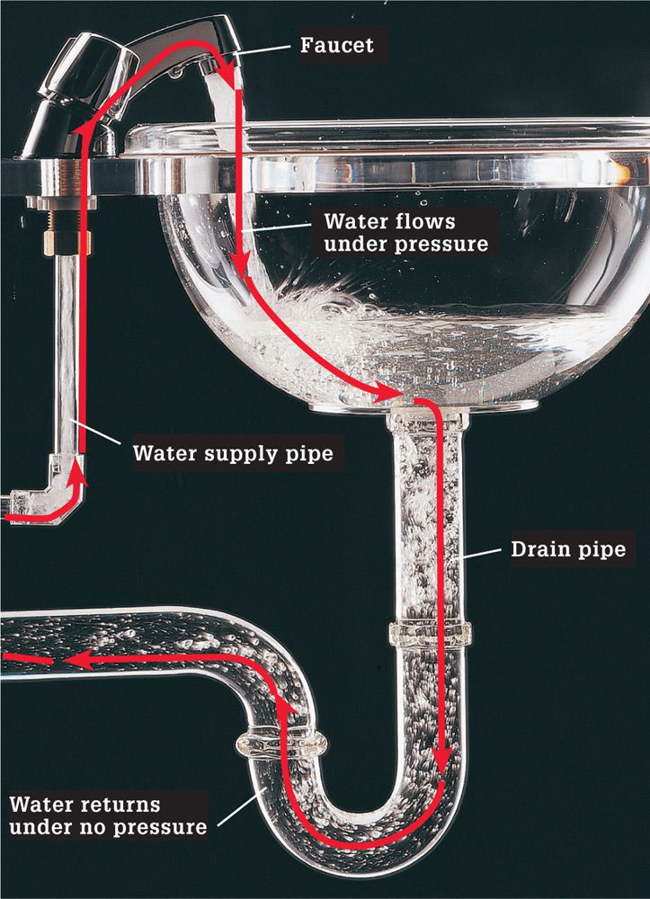
Water and electricity both flow. The main difference is that you can see water (and touching water isn’t likely to kill you). Like electricity, water enters a fixture under high pressure and exits under no pressure.
![]() The Delivery System
The Delivery System
Electricity that enters the home is produced by large power plants. Power plants are located in all parts of the country and generate electricity with generators that are turned by water, wind, or steam. From these plants electricity enters large “step-up” transformers that increase voltage to half a million volts or more.
Electricity flows at these high voltages and travels through high-voltage transmission wires to communities that can be hundreds of miles from the power plants. “Step-down” transformers located at substations then reduce the voltage for distribution along street wires. On utility power poles, smaller transformers further reduce the voltage to ordinary 120-volt electricity for household use.
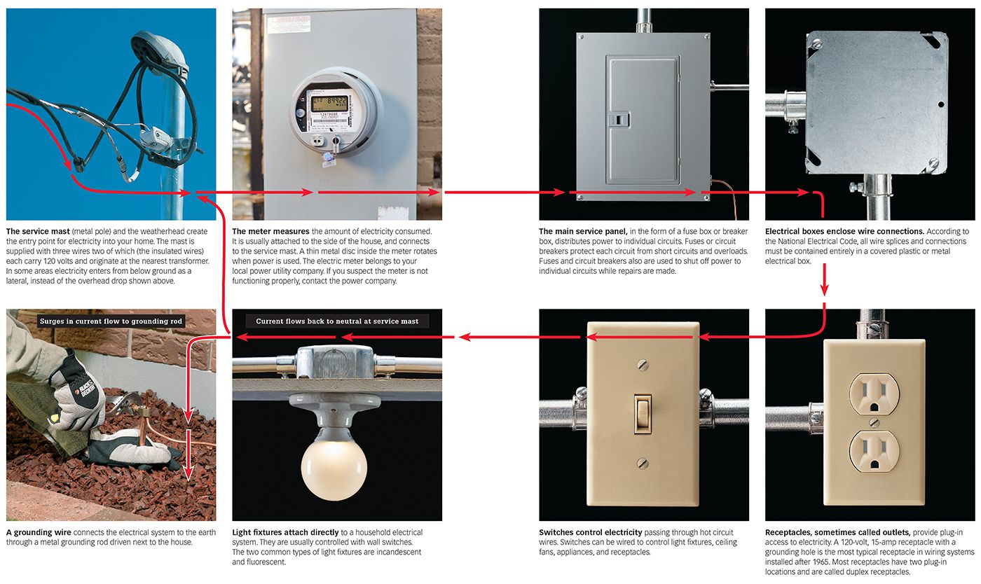
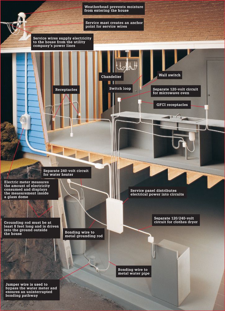
Wires carrying electricity to a house either run underground or are strung overhead and attached to a post called a service mast. Most homes built after 1950 have three wires running to the service head: two power wires, each carrying 120 volts, and a grounded neutral wire. Electricity from the two 120-volt wires may be combined at the service panel to supply electricity to large 240-volt appliances such as clothes dryers or electric water heaters.
Incoming electricity passes through a meter that measures electricity consumption. Electricity then enters the service panel, where it is distributed to circuits that run throughout the house. The service panel also contains fuses or circuit breakers that shut off power to the individual circuits in the event of a short circuit or an overload. Certain high-wattage appliances, such as microwave ovens, are usually plugged into their own individual circuits to prevent overloads.
Voltage ratings determined by power companies and manufacturers have changed over the years. These changes do not affect the performance of new devices connected to older wiring. For making electrical calculations, use a rating of 120 volts or 240 volts for your circuits.

Power plants supply electricity to thousands of homes and businesses. Step-up transformers increase the voltage produced at the plant.
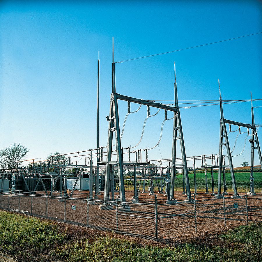
Substations are located near the communities they serve. A typical substation takes electricity from high-voltage transmission wires and reduces it for distribution along street wires.
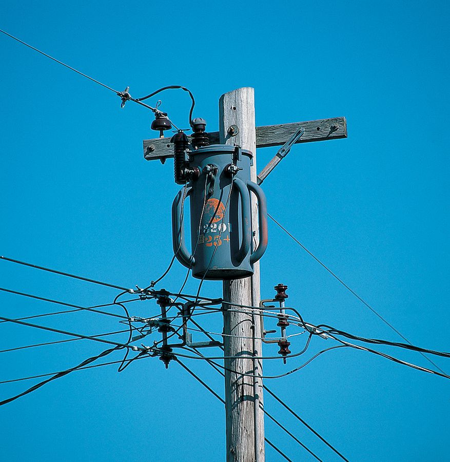
Electrical transformers reduce the high-voltage electricity that flows through wires along neighborhood streets. A utility pole transformer—or ground transformer—reduces voltage from 10,000 volts to the normal 120-volt electricity used in households.
![]() Parts of the Electrical System
Parts of the Electrical System
Glossary of Electrical Terms ![]()
Ampere (or amp): Refers to the rate at which electrical current flows to a light, tool, or appliance.
Armored cable: An assembly of insulated wires enclosed in a flexible, interlocked metallic armor.
Box: A device used to contain wiring connections.
BX: A brand name for an early type of armored cable that is no longer made. The current term is armored cable.
Cable: Two or more wires that are grouped together and protected by a covering or sheath.
Circuit: A continuous loop of electrical current flowing along wires.
Circuit breaker: A safety device that interrupts an electrical circuit in the event of an overload or short circuit.
Conductor: Any material that allows electrical current to flow through it. Copper wire is an especially good conductor.
Conduit: A metal or plastic pipe used to protect wires.
Continuity: An uninterrupted electrical pathway through a circuit or electrical fixture.
Current: The flow of electricity along a conductor.
Duplex receptacle: A receptacle that provides connections for two plugs.
Flexible metal conduit (FMC): Hollow, coiled steel or aluminum tubing that may be filled with wires (similar to Armored Cable, but AC is pre-wired).
Fuse: A safety device, usually found in older homes, that interrupts electrical circuits during an overload or short circuit.
Greenfield: A brand name for an early type of flexible metal conduit. The current term is flexible metal conduit. Note: flexible metal conduit is different from armored cable.
Grounded wire: See neutral wire.
Grounding wire: A wire used in an electrical circuit to conduct current to the service panel in the event of a ground fault. The grounding wire often is a bare copper wire.
Hot wire: Any wire that carries voltage. In an electrical circuit, the hot wire usually is covered with black or red insulation.
Insulator: Any material, such as plastic or rubber, that resists the flow of electrical current. Insulating materials protect wires and cables.
Junction box: See box.
Meter: A device used to measure the amount of electrical power being used.
Neutral wire: A wire that returns current at zero voltage to the source of electrical power. Usually covered with white or light gray insulation. Also called the grounded wire.
Non-metallic sheathed cable: NM cable consists of two or more insulated conductors and, in most cases, a bare ground wire housed in a durable PVC casing.
Outlet: A place where electricity is taken for use. A receptacle is a common type of outlet. A box for a ceiling fan is another type of outlet.
Overload: A demand for more current than the circuit wires or electrical device was designed to carry. This should cause a fuse to blow or a circuit breaker to trip.
Pigtail: A short wire used to connect two or more wires to a single screw terminal.
Polarized receptacle: A receptacle designed to keep hot current flowing along black or red wires and neutral current flowing along white or gray wires.
Power: The work performed by electricity for a period of time. Use of power makes heat, motion, or light.
Receptacle: A device that provides plug-in access to electricity.
Romex: A brand name of plastic-sheathed electrical cable that is commonly used for indoor wiring. Commonly known as NM cable.
Screw terminal: A place where a wire connects to a receptacle, switch, or fixture.
Service panel: A metal box usually near the site where electricity enters the house. In the service panel, electrical current is split into individual circuits. In residences, the service panel has circuit breakers or fuses to protect each circuit.
Short circuit: An accidental and improper contact between two current-carrying wires or between a current-carrying wire and a grounding conductor.
Switch: A device that controls electricity passing through hot circuit wires. Used to turn lights and appliances on and off.
UL: An abbreviation for Underwriters Laboratories, an organization that tests electrical devices and manufactured products for safety.
Voltage (or volts): A measurement of electricity in terms of pressure.
Wattage (or watt): A measurement of electrical power in terms of total work performed. Watts can be calculated by multiplying the voltage times the amps.
Wire connector: A device used to connect two or more wires together. Also called a wire nut.
![]() Understanding Electrical Circuits
Understanding Electrical Circuits
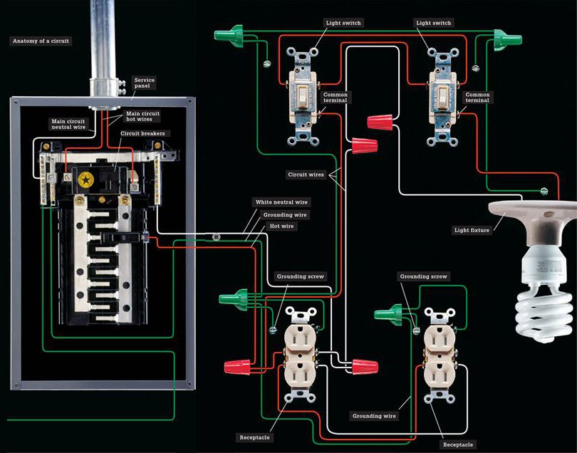
An electrical circuit is a continuous loop. Household circuits carry electricity from the main service panel, throughout the house, and back to the main service panel. Several switches, receptacles, light fixtures, or appliances may be connected to a single circuit.
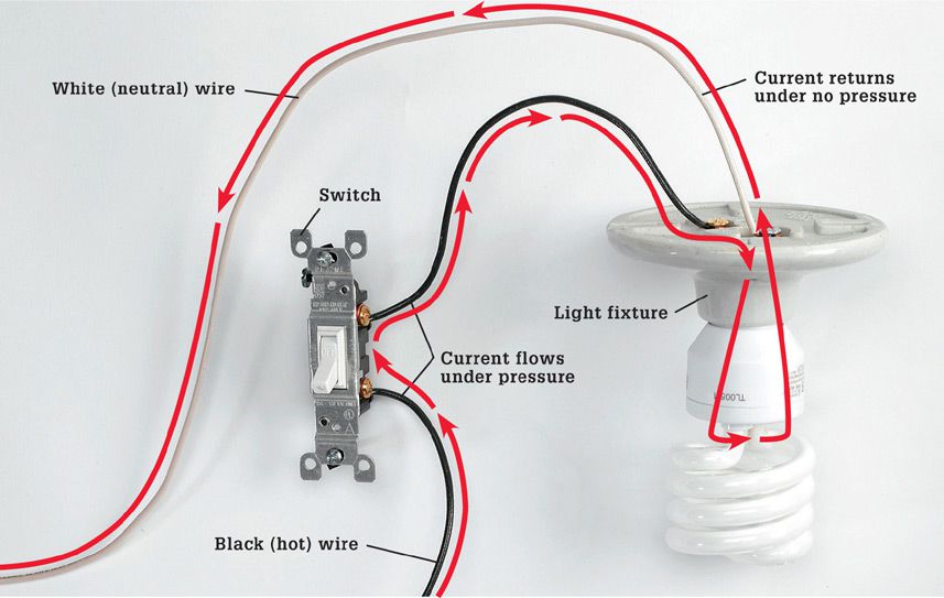
Current enters a circuit loop on hot wires and returns along neutral wires. These wires are color coded for easy identification. Hot wires are black or red, and neutral wires are white or light gray. For safety, all modern circuits include a bare copper or green insulated grounding wire. The grounding wire conducts current in the event of a ground fault (see page 165) and helps reduce the chance of severe electrical shock. The service panel also has a bonding wire connected to a metal water pipe and a grounding wire connected to a metal grounding rod, buried underground, or to another type of grounding electrode.
If a circuit carries too much current, it can overload. A fuse or a circuit breaker protects each circuit in case of overloads.
Current returns to the service panel along a neutral circuit wire. Current then leaves the house on a large neutral service wire that returns it to the utility transformer.
![]() Grounding & Polarization
Grounding & Polarization
Electricity always seeks to return to its source and complete a continuous circuit. Contrary to popular belief, electricity will take all available return paths to its source, not just the path of lowest resistance. In a household wiring system, this return path is provided by white neutral wires that return current to the main service panel. From the service panel, current returns along the uninsulated neutral service wire to a power pole transformer.
You will see the terms grounding and bonding used in this and other books about electricity. These terms are often misunderstood. You should understand the difference to safely work on electrical circuits.
Bonding connects the non-current-carrying metal parts of the electrical system, such as metal boxes and metal conduit, in a continuous low-resistance path back to the main service panel. If this metal becomes energized (a ground fault), current travels on the bonded metal and quickly increases to an amount that trips the circuit breaker or blows the fuse. The dead circuit alerts people to a problem.
Other metal that could become energized also must be bonded to the home’s electrical system. Metal water and gas pipes are the most common examples. A metal water and gas pipe could become energized by coming in contact with a damaged electrical wire. Metal gas pipe could become energized by a ground fault in a gas appliance such as a furnace.
Bonding is a very important safety system. A person could receive a fatal shock if he or she touches energized metal that is improperly bonded, because that person becomes electricity’s return path to its source. Bonding is also a fire safety system that reduces the chance of electrical fires.
Grounding connects the home’s electrical system to the earth. Grounding’s primary purpose is to help stabilize voltage fluctuations caused by lightning and other problems in the electrical grid. Grounding also provides a secondary return path for electricity in case there is a problem in the normal return path.
Grounding is accomplished by connecting a wire between the main service panel and a grounding electrode. The most common grounding electrode is a buried copper rod. Other grounding electrodes include reinforcing steel in the footing, called a ufer ground.
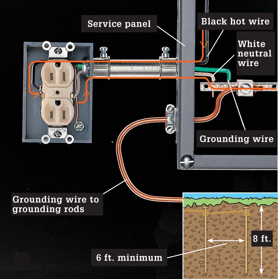
Normal current flow: Current enters the electrical box along a black hot wire and then returns to the service panel along a white neutral wire.
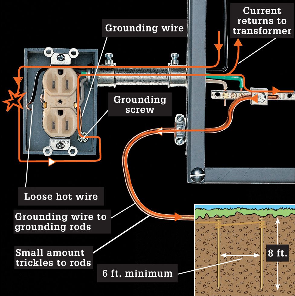
Ground Fault: Current is detoured by a loose wire in contact with the metal box. The grounding wire and bonded metal conduit pick it up and channel it back to the main service panel, where the overcurrent device is tripped, stopping further flow of current. Most current in the bonding and ground system flows back to the transformer; some may trickle out through the copper that leads to the grounding node.
Grounding of the home electrical system is accomplished by wiring the household electrical system to a metal cold water pipe and metal grounding rods that are buried in the earth.
After 1920, most American homes included receptacles that accepted polarized plugs. The two-slot polarized plug and receptacle was designed to keep hot current flowing along black or red wires and neutral current flowing along white or gray wires.
The metal jacket around armored cable and flexible metal conduit, widely installed in homes during the 1940s, provided a bonding path. When connected to metal junction boxes, it provided a metal pathway back to the service panel. Note, however, that deterioration of this older cable may decrease its effectiveness as a bonding conductor.
Modern cable includes a green insulated or bare copper wire that serves as the bonding path. This grounding wire is connected to all three-slot receptacles and metal boxes to provide a continuous pathway for any ground-faulted current. By plugging a three-prong plug into a grounded three-slot receptacle, people are protected from ground faults that occur in appliances, tools, or other electric devices.
Use a receptacle adapter to plug three-prong plugs into two-slot receptacles, but use it only if the receptacle connects to a grounding wire or grounded electrical box. Adapters have short grounding wires or wire loops that attach to the receptacle’s coverplate mounting screw. The mounting screw connects the adapter to the grounded metal electrical box.
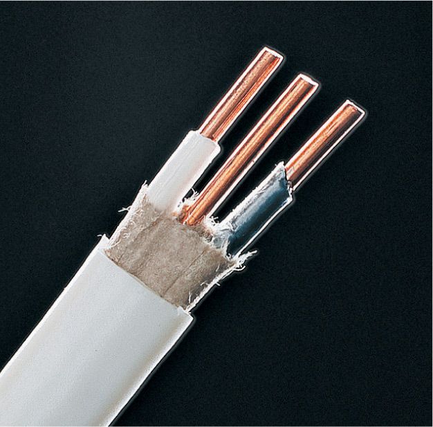
Modern NM (nonmetallic) cable, found in most wiring systems installed after 1965, contains a bare copper wire that provides bonding for receptacle and switch boxes.
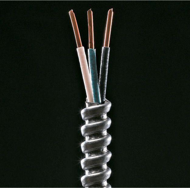
Armored cable is sold pre-installed in a flexible metal housing. It contains a green insulated ground wire along with black and white conductors. Flexible metal conduit (not shown) is sold empty.
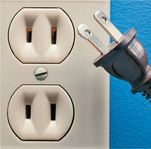
Polarized receptacles have a long slot and a short slot. Used with a polarized plug, the polarized receptacle keeps electrical current directed for safety.
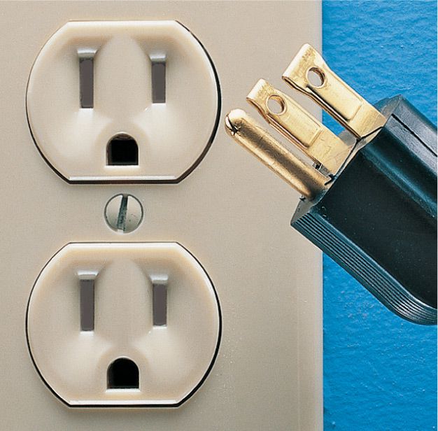
Tamper resistent three-slot receptacles are required by code for new homes. They are usually connected to a standard two-wire cable with ground.
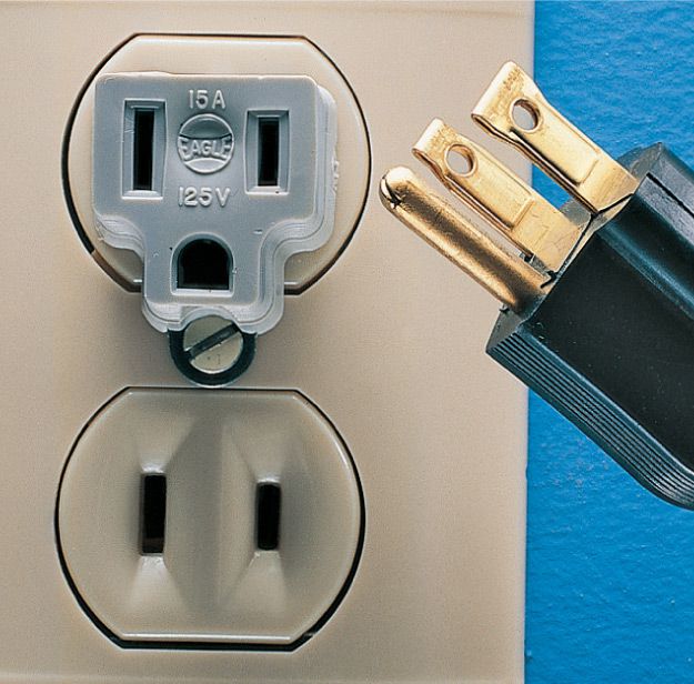
A receptacle adapter allows three-prong plugs to be inserted into two-slot receptacles. The adapter should only be used with receptacles mounted in a bonded metal box, and the grounding loop or wire of the adapter must be attached to the coverplate mounting screw.
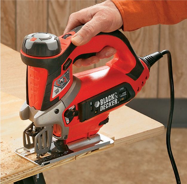
Double-insulated tools have non-conductive plastic bodies to prevent shocks caused by ground faults. Because of these features, double-insulated tools can be used safely with ungrounded receptacles.
![]() Home Wiring Tools
Home Wiring Tools
To complete the wiring projects shown in this book, you need a few specialty electrical tools as well as a collection of basic hand tools. As with any tool purchase, invest in quality products when you buy tools for electrical work. Keep your tools clean, and sharpen or replace any cutting tools that have dull edges.
The materials used for electrical wiring have changed dramatically in the last 20 years, making it much easier for homeowners to do their own electrical work. The following pages show how to work with the following components for your projects.
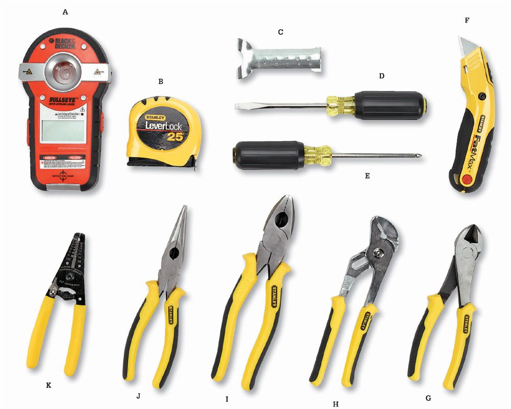
Hand tools you’ll need for home wiring projects include: Stud finder/laser level (A) for locating framing members and aligning electrical boxes; tape measure (B); a cable ripper (C) for scoring NM sheathing; standard (D) and Phillips (E) screwdrivers; a utility knife (F); side cutters (G) for cutting wires; channel-type pliers (H) for general gripping and crimping; linesman pliers (I) that combine side cutter and gripping jaws; needlenose pliers (J); wire strippers (K) for removing insulation from conductors.
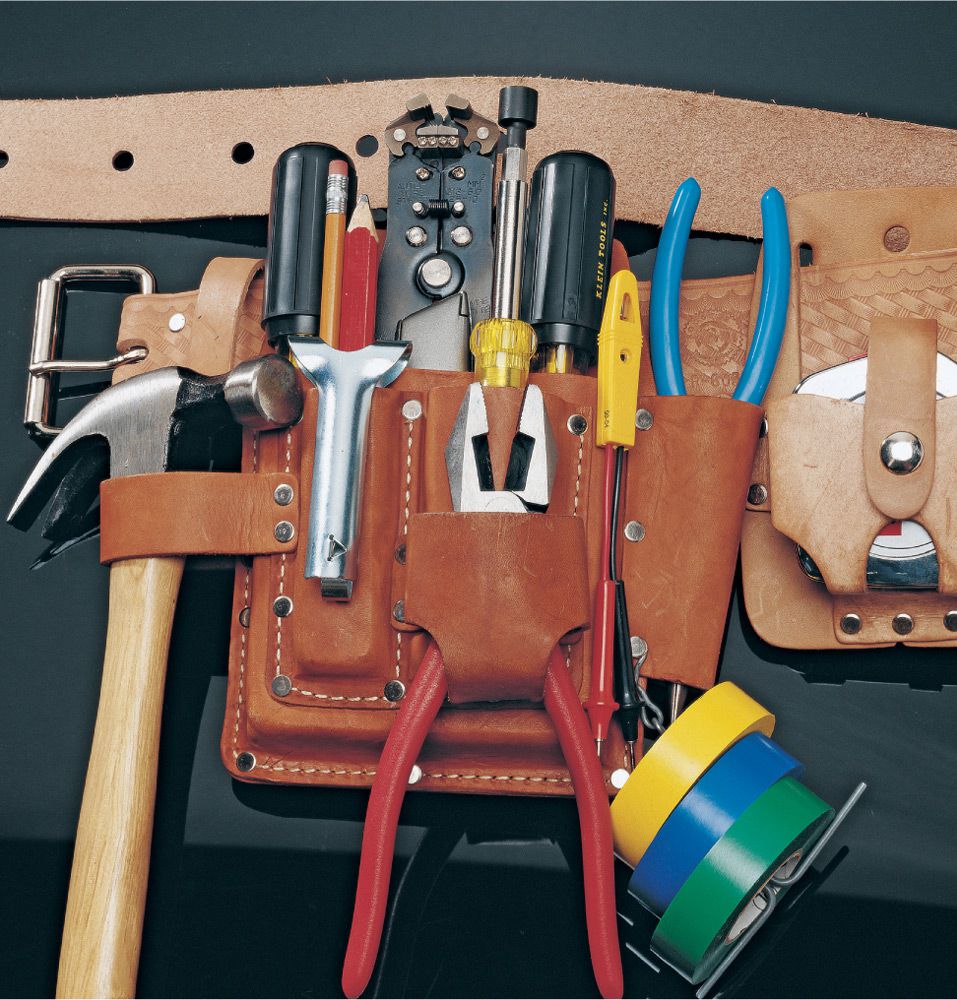
Use a tool belt to keep frequently used tools within easy reach. Electrical tapes in a variety of colors are used for marking wires and for attaching cables to a fish tape.
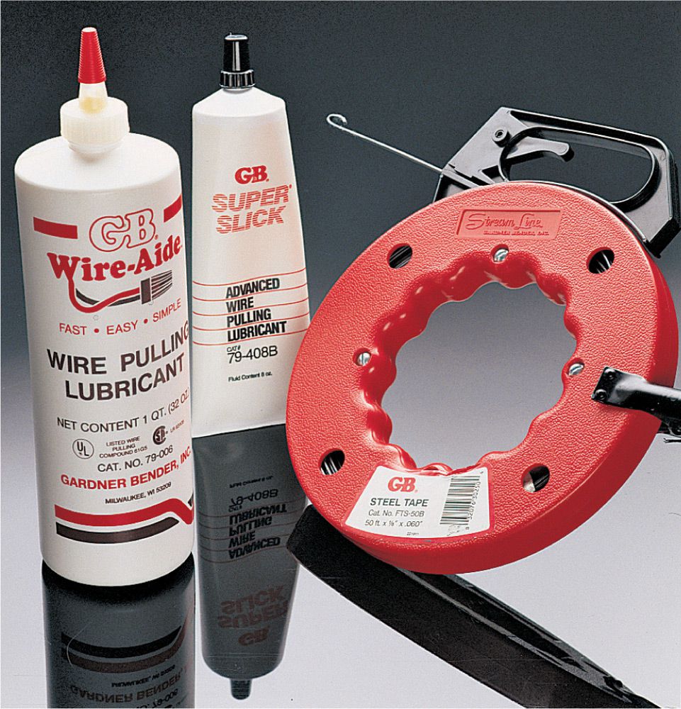
A fish tape is useful for installing cables in finished wall cavities and for pulling wires through conduit. Products designed for lubrication reduce friction and make it easier to pull cables and wires.
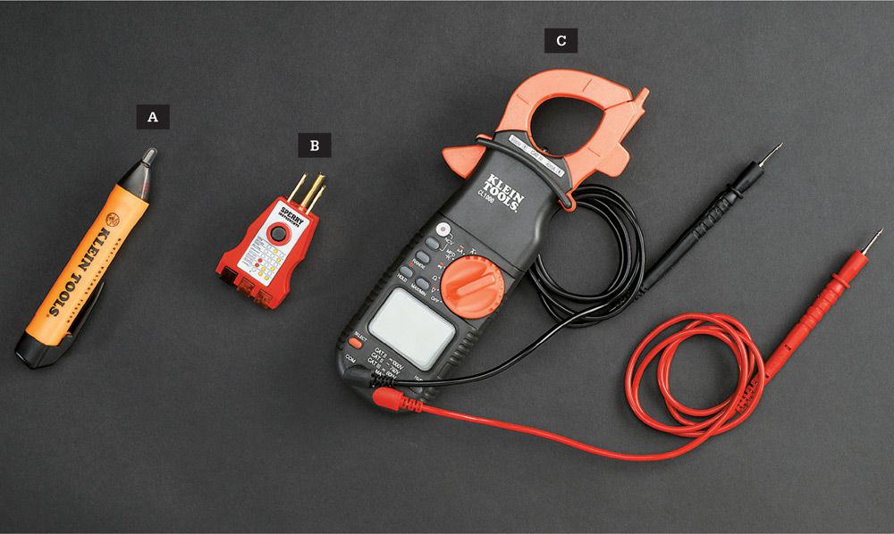
Diagnostic tools for home wiring use include: A touchless circuit tester (A) to safely check wires for current and confirm that circuits are dead; a plug-in tester (B) to check receptacles for correct polarity, grounding, and circuit protection; a multimeter (C) to measure AC/DC voltage, AC/DC current, resistance, capacitance, frequency, and duty cycle (model shown is an auto-ranging digital multimeter with clamp-on jaws that measure through sheathing and wire insulation).
![]() Wiring Safety
Wiring Safety
Safety should be the primary concern of anyone working with electricity. Although most household electrical repairs are simple and straightforward, always use caution and good judgment when working with electrical wiring or devices. Common sense can prevent accidents.
The basic rule of electrical safety is: Always turn off power to the area or device you are working on. At the main service panel, remove the fuse or shut off the circuit breaker that controls the circuit you are servicing. Then check to make sure the power is off by testing for power with a voltage tester. Tip: Test a live circuit with the voltage tester to verify that it is working before you rely on it. Restore power only when the repair or replacement project is complete.
Follow the safety tips shown on these pages. Never attempt an electrical project beyond your skill or confidence level.
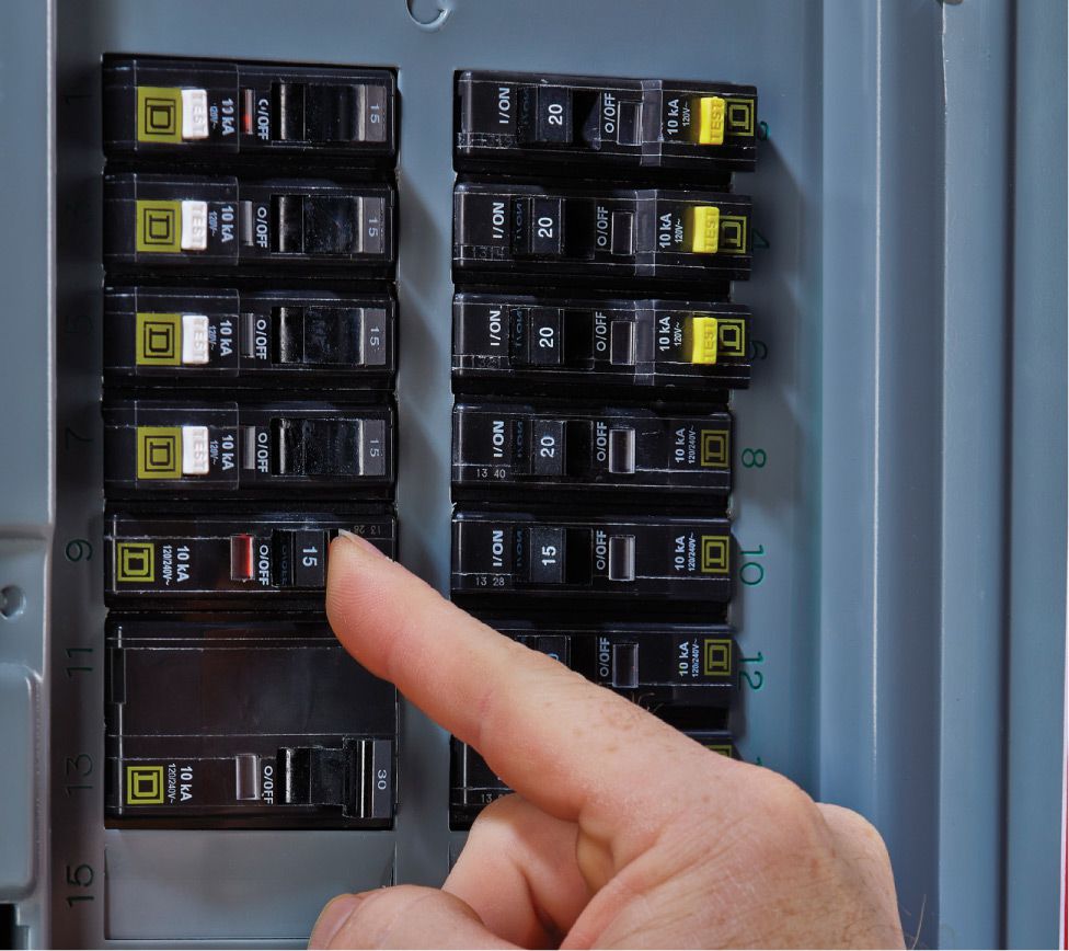
Shut power OFF at the main service panel or the main fuse box before beginning any work.
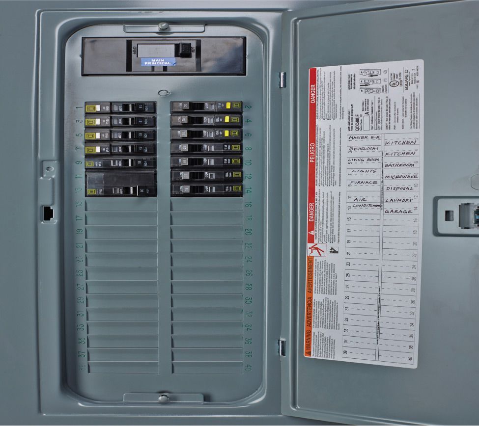
Create a circuit index and affix it to the inside of the door to your main service panel. Update it as needed.
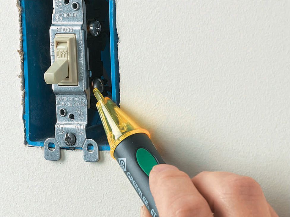
Confirm power is OFF by testing at the outlet, switch, or fixture with a voltage tester.
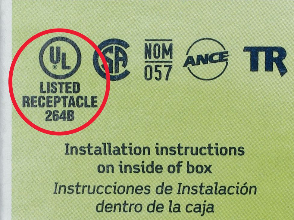
Use only UL-approved electrical parts or devices. These devices have been tested for safety by Underwriters Laboratories.

Wear rubber-soled shoes while working on electrical projects. On damp floors, stand on a rubber mat or dry wooden boards.
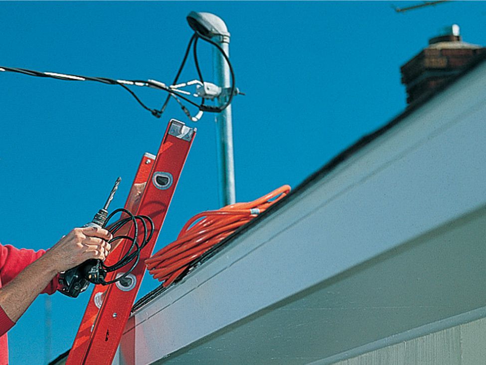
Use fiberglass or wood ladders when making routine household repairs near the service mast.
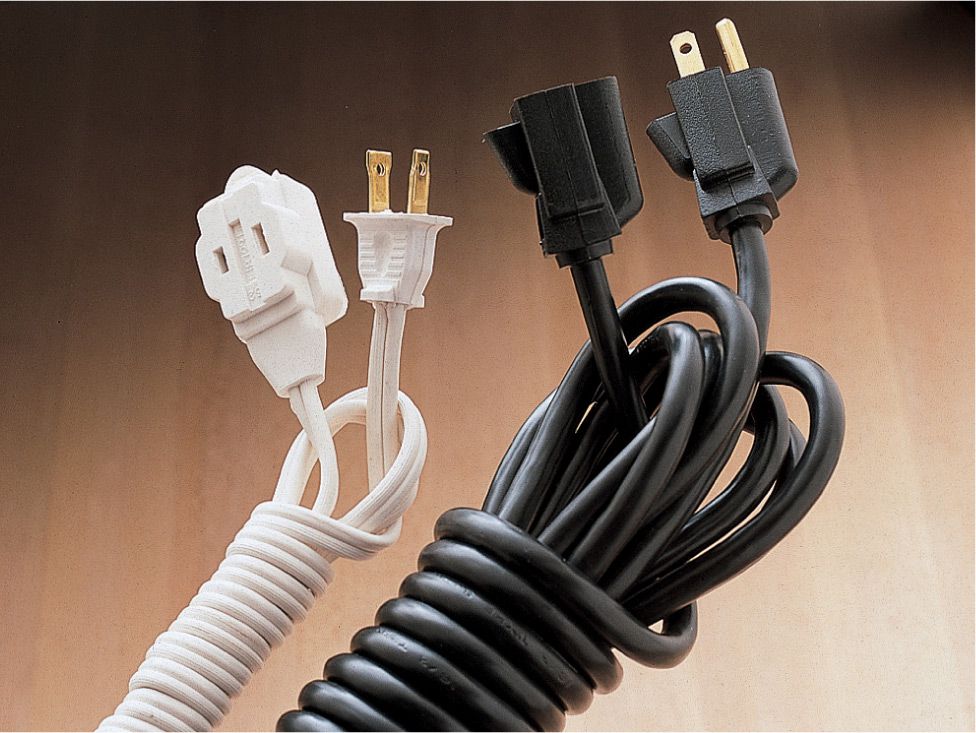
Extension cords are for temporary use only. Cords must be rated for the intended usage.
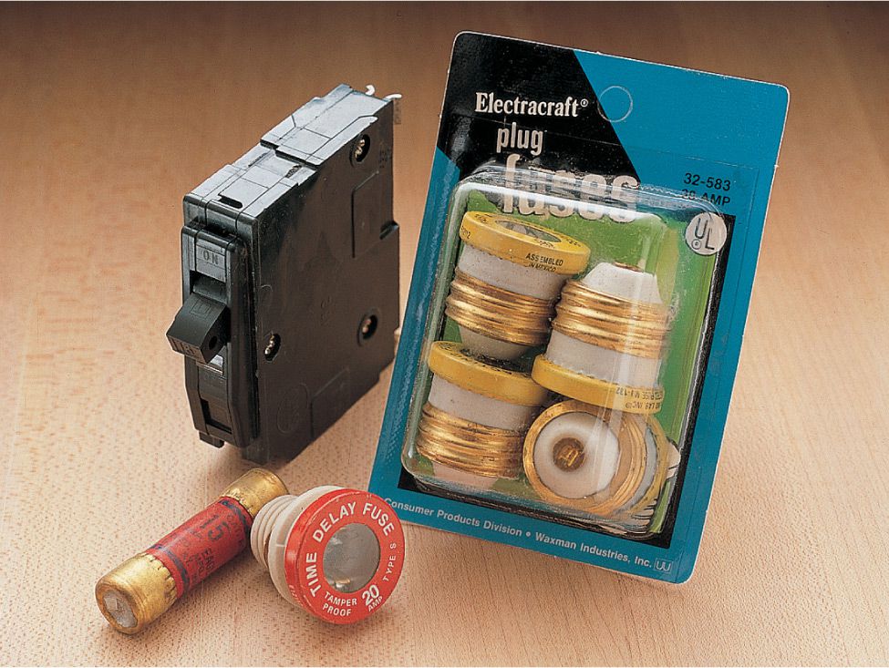
Breakers and fuses must be compatible with the panel manufacturer and match the circuit capacity.
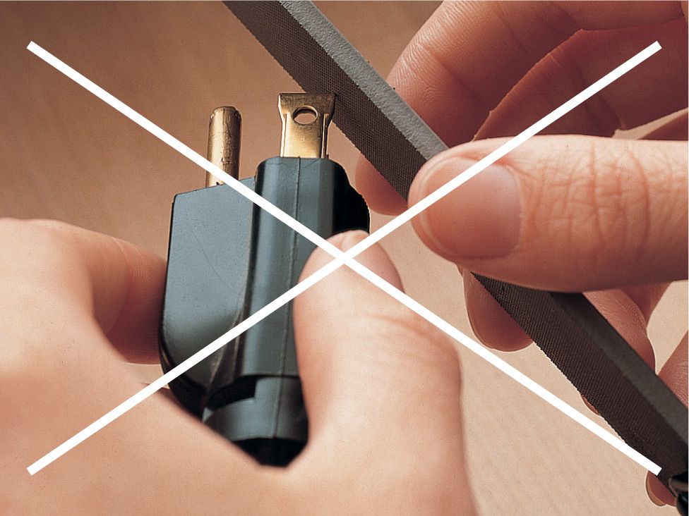
Never alter the prongs of a plug to fit a receptacle. If possible, install a new grounded receptacle.
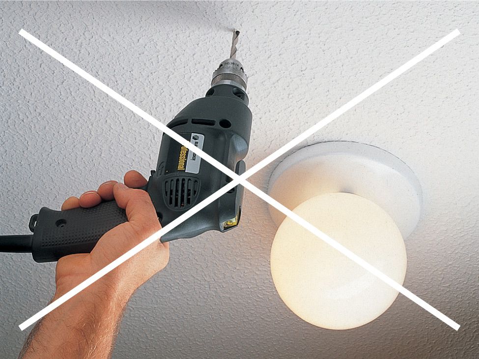
Do not penetrate walls or ceilings without first shutting off electrical power to the circuits that may be hidden.