The Car Hacker's Handbook: A Guide for the Penetration Tester - Craig Smith (2016)
Chapter 6. ECU HACKING
by Dave Blundell

A vehicle typically has as many as a dozen or more electronic controllers, many of which are networked to communicate with each other. These computerized devices go by many different names, including electronic control unit or engine control unit (ECU), transmission control unit (TCU), or transmission control module (TCM).
While these terms may have specific meanings in a formal setting, similar terms are often used interchangeably in practice. What may be a TCU to one manufacturer is a TCM to another, yet both electronic controllers perform the same or extremely similar functions.
Most automotive control modules have measures in place to prevent you from altering their code and operation; these range from very strong to laughably weak. You won’t know what you’re dealing with until you investigate a particular system. In this chapter, we’ll take a closer look at particular security mechanisms, but first we’ll examine strategies for gaining access to these systems. Then in Chapter 8 we’ll look at some more specific ECU hacks, like glitch attacks and debugging. The attack vectors for ECUs fall into three different classes:
Front door attacks Commandeering the access mechanism of the original equipment manufacturer (OEM)
Backdoor attacks Applying more traditional hardware-hacking approaches
Exploits Discovering unintentional access mechanisms
We’ll look at an overview of these attack classes, and then analyze the data you find. It’s worth remembering that while the goal for ECU and other control module hacking is often the same—to gain access in order to reprogram and change behavior—it’s unlikely there’ll be a “master key” for all controllers. However, OEMs are generally not very creative and seldom change their ways, so insight into one controller likely applies to similar models from the same manufacturer. Also, few of today’s auto manufacturers develop their own automotive computers from scratch, instead licensing prefabricated solutions from third parties like Denso, Bosch, Continental, and others. Because of this design methodology, it’s relatively common to see vehicles from different auto manufacturers using very similar computer systems sourced from the same vendors.
Front Door Attacks
The OBD-II standard mandates that you be able to reprogram vehicles through the OBD-II connector, and reverse engineering the original method for programming is a guaranteed attack vector. We’ll examine J2534 and KWP2000 as examples of common protocols for programming.
J2534: The Standardized Vehicle Communication API
The SAE J2534-1 standard, or simply J2534, was developed to promote interoperability among digital tool vendors through the use of the J2534 API, which outlines the recommended way for Microsoft Windows to communicate with a vehicle. (You can purchase the J2534 API from the SAE at http://standards.sae.org/j2534/1_200412/.) Prior to the adoption of the J2534 standard, each software vendor created its own proprietary hardware and drivers for communicating with a vehicle in order to perform computerized repairs. Because these proprietary tools weren’t always available to smaller shops, the EPA mandated the adoption of the J2534 standard in 2004 to allow independent shops access to the same specialized computer tools used by dealerships. J2534 introduced a series of DLLs that map standard API calls to instructions necessary to communicate with a vehicle, thereby allowing multiple manufacturers to release software designed to work with J2534-compatible hardware.
Using J2534 Tools
J2534 tools provide a convenient way to observe OEM tools interacting with vehicle computers. Manufacturers often leverage J2534 to update computer firmware and sometimes to provide powerful diagnostic software. By observing and capturing information exchanged with a vehicle using J2534, you can see how OEMs perform certain tasks, which may provide you with information that you need to unlock the “front door.”
When using J2534 tools to attack vehicle systems, the basic idea is to observe, record, analyze, and extend functionality. Of course, the first step is to obtain and configure a J2534 application and its corresponding interface hardware in order to perform a task you want to observe. Once you have your setup, the next step is to observe and record communications with the target while using the J2534 tools to perform an action on the target, like updating a configuration parameter.
There are two primary ways to observe J2534 transactions: by watching J2534 API calls on a PC using J2534 shim DLLs or by watching actual bus traffic using a separate sniffer tool to capture data.
J2534 tools are key to eavesdropping on the protocols built into the factory embedded vehicle systems, and they’re one of the primary ways to attack the front door. Successful analysis of this communication will give you the knowledge you need to access vehicle systems the way the OEMs do. It’ll also allow you to write applications with full access to read and reprogram systems, which will in turn enable you to communicate directly with a vehicle without having to use the J2534 interface or the OEM’s J2534 software.
J2534 Shim DLLs
The J2534 shim is a software J2534 interface that connects to a physical J2534 interface and then passes along and logs all commands that it receives. This dummy interface is a kind of man-in-the-middle attack that allows you to record all API calls between the J2534 application and the target. You can then examine the log of commands to determine the actual data exchanged between the J2534 interface and the device.
To find an open source J2534 shim, search code.google.com for J2534-logger. You should also be able to find precompiled binaries.
J2534 with a Sniffer
You can also use J2534 to generate interesting traffic that you can then observe and record with a third party sniffer. There’s no magic here: this is just an excellent example of how to generate juicy packets that might otherwise be difficult to capture. (See Chapter 5 for more information on monitoring network traffic.)
KWP2000 and Other Earlier Protocols
Before J2534, there were many flash-programmable ECUs and other control units, such as the Keyword Protocol 2000 (KWP2000 or ISO14230). From an OSI networking perspective, it’s primarily an application protocol. It can be used on top of CAN or ISO9141 as the physical layer. You’ll find a huge number of KWP2000 flasher tools that interface with a PC using a serial/ USB-serial interface and that support diagnostics and flashing using this protocol just by searching online. (For more on the Keyword Protocol 2000, see Chapter 2.)
Capitalizing on Front Door Approaches: Seed-Key Algorithms
Now that we’ve discussed how legitimate tools use the front door, it’s time to capitalize on this attack vector by learning how to operate the figurative “lock on the gate.” To do this, we must understand the algorithm that the embedded controller uses to authenticate valid users; this is almost always a seed-key algorithm. Seed-key algorithms usually generate a pseudorandom seed and expect a particular response, or key, for each seed before allowing access. A typical valid exchange could look something like this:
ECU seed: 01 C3 45 22 84
Tool key: 02 3C 54 22 48
or this:
ECU seed: 04 57
Tool key: 05 58
Unfortunately, there’s no standard seed-key algorithm. You might have a 16-bit seed and 16-bit key, a 32-bit seed and 16-bit key, or a 32-bit seed and 32-bit key. The algorithm that generates a key from a given seed also varies from platform to platform. Most algorithms are a combination of simple arithmetic operations and one or more values used as part of the computation. There are several techniques for figuring out these algorithms in order to give you access to the ECU:
✵ Obtain the firmware for the device in question through other means. Disassemble it and analyze the embedded code to find the code responsible for generating seed-key pairs.
✵ Obtain a legitimate software tool—for example, J2534 reflash software—that’s capable of generating legitimate seed-key pairs, and analyze the PC application code with a disassembler to determine the algorithm used.
✵ Observe a legitimate tool exchanging keys, and analyze the pairs for patterns.
✵ Create a device to spoof a legitimate tool into providing responses repeatedly. The main advantage of this method over purely passive observation is that it allows you to pick seeds for which you can reproduce the keys.
You can find more information about reverse engineering the seed-key algorithms used by General Motors at http://pcmhacking.net/forums/viewtopic.php?f=4&t=1566&start=10, and those used by VAG MED9.1 at http://nefariousmotorsports.com/forum/index.php?topic=4983.0.
Backdoor Attacks
Sometimes front door attacks are too tricky; you may not have the right tools or the lock might be too hard to figure out. Don’t despair—remember that automotive control modules are embedded systems, so you can use all the usual hardware-hacking approaches. In fact, using more direct-to-hardware backdoor approaches often makes more sense than trying to reverse engineer the front door lock placed by the factory, especially when trying to reprogram engine modules. If you can obtain a dump of the module, you can often disassemble and analyze it to figure out how the keys to the front door work. The first step in a hardware backdoor attack is analyzing the circuit board.
When reversing a circuit board of any system, you should start with the largest chips first. These larger processor and memory chips are likely to be the most complex. It’s a good idea to make a list of part numbers to feed to Google, datasheet.com, or something similar, to obtain a copy of the data sheet. You’ll sometimes encounter custom application-specific integrated circuits (ASICs) and one-off chips, especially with older ECUs, which will prove more difficult than off-the-shelf parts. In many cases, you’ll have to infer the function of these parts based on how they’re connected to identifiable parts.
It’s critical to look out for memory chips—SRAM, EEPROM, FlashROM, one-time-programmable ROM, serial EEPROM, serial flash, NVSRAM, and so on. The type of memory used varies immensely from one platform to another; every single variety listed here has been found in the wild. Newer designs are less likely to have parallel memories and more likely to have serial chips. Newer microcontrollers are less likely to have any external memories at all, as their internal flash capacities have dramatically increased. Any nonvolatile memory chip present can be removed from the circuit board, read, and then replaced. Chapter 8 goes into much more detail on reverse engineering the circuit board.
Exploits
Although arguably just another example of a backdoor approach, exploits deserve special attention. Rather than taking apart a computer, exploits involve feeding a system carefully crafted inputs to make it do things outside normal operation. Typically, exploits build on a bug or problem. This bug might cause a system to crash, reboot, or perform some undesirable behavior from the perspective of the vehicle user. Some of these bugs present the opportunity for buffer overflow attacks, which open the door for commandeering the vulnerable device merely by feeding it unexpected inputs. A cleverly crafted set of inputs triggers the bug, which then makes the device execute arbitrary code provided by the attacker instead of triggering the usual fault condition.
Not all bugs can be turned into exploits, however—some bugs only cause problems or shut down core systems. And while bugs are usually discovered by accident, most exploits require careful craft. It is unlikely that you’d be able to turn a known bug into an exploit without also having prior knowledge of the system, usually gained from firmware analysis. At a bare minimum, you’d need basic knowledge of the architecture in order to write the necessary code. Most of the time, this knowledge needs to be gathered through research prior to writing an exploit.
It’s hard to find bugs that make suitable attack vectors and it’s often just as difficult to write exploits for them, so exploits that build on bugs are fairly uncommon. While it is foolish to discount the relevance of exploits, the other methods presented here and in Chapter 8 are much more practical paths to understanding and reprogramming automotive systems in most cases.
Reversing Automotive Firmware
Hacking into an automotive control module far enough to retrieve its current firmware and configuration is really just the beginning of the adventure. At this point, you probably have anywhere from 4KB to 4MB of raw machine-ready code, with a mixture of various parameters and actual code that forms the program the processor will run. Let’s say you have a binary blob in the firmware from one of the hacks in this chapter or the chapters later in this book. Next you need to disassemble the binary.
First, you must know which chip this binary is for. There are several free decompilers for different chips out on the Internet. Otherwise you can drop some cash and buy IDA Pro, which supports a large variety of chips. These tools will convert the hex values in the binary into assembler instructions. The next stage is to figure out what exactly you are looking at.
When you’re starting to analyze raw data, a high-level understanding of the function of the devices you’re reverse engineering will be key to knowing what to look for. You can follow a number of breadcrumbs, or clues, for starters; these breadcrumbs are almost guaranteed to lead you to interesting and useful material. Next, we’ll look at a few specific examples of how to use common automotive controller functions to gain insight into their operation, which will hopefully allow us to change their behavior.
Self-Diagnostic System
Every engine controller has some type of self-diagnostic system that typically monitors most critical engine functions, and analyzing this is an excellent route to understanding firmware. A good first step in investigative disassembly is to identify the location of these procedures. This will provide you with insight into the memory locations involved in all of the sensors and functions that are checked for errors. Any modern vehicle should support OBD-II packets, which standardize the diagnostic data reported. Even controllers created prior to OBD-II standards have a way to report faults. Some have a system where an analog input is shorted to ground and either an internal LED or the “check engine” light flashes out the code. For example, knowing that code 10 refers to a failed intake air temperature sensor means you can find the piece of code that sets error code 10 to help you identify the internal variables associated with the air temperature sensor.
For more detailed information on using diagnostics, see Chapter 4.
Library Procedures
Being able to change the behavior of a control unit is often one of the primary goals of reverse engineering ECU firmware, and identifying data used by a controller is an important step in the process. Most ECUs have a set of library functions used for routine tasks throughout the code. Library functions used for table lookups are worth identifying early on in the reverse engineering process, as these can lead straight to the parameters you’re interested in. Each time a table is used, a function is called to fetch a result. Calls to this type of function are among the most frequent, making them easy to spot.
Usually each type of data stored within the ECU—one-dimensional array of bytes; two-dimensional array of words; three-dimensional array of unsigned, signed, and float shorts; and so on—has a unique reference function. When called, each table lookup routine needs to be passed, at a minimum, the table index (or start address) and the axis variables. Often, table lookup routines can be reused to pass information about the structure of the table, such as how many rows and columns are present.
Calibration data is usually stored in program memory, along with the routines accessing them. Microcontrollers typically have special instructions to access program memory, which provide a unique signature to search for and make table lookup routines particularly easy to spot. A secondary characteristic of these lookup routines is that they tend to have lots of interpolation math. In addition, table lookup routines are often grouped closely together in program memory, making it even easier to find others after you’ve found one. After identifying reference routines, searching for all calls to them can provide a key to identifying the vast majority of data used by the controller to make decisions. The arguments passed to these functions typically include the start address of a table, its structure or shape, and which variables index elements of the table. Armed with this information, you’re much closer to being able to change the behavior of the controller.
Finding Known Tables
One way to identify tables is to leverage the specific physical and electrical characteristics of vehicle sensors, which will display identifiable characteristics within ECU firmware. For example, an ECU with a MAF sensor will have a table that translates raw readings of voltage or frequency from the MAF into airflow into the engine, providing an internal representation.
Fortunately for us, the signal output from an MAF is determined by physics—that is, King’s Law—so the curve will always have a characteristic shape, though it’ll be slightly different for each sensor. This will result in the tables having a characteristic set of values that can be observed in the ROM. Armed with the knowledge that there will be universal data to identify, let’s take a closer look at how calibration data is displayed in different programs.
Figures 6-1 and 6-2 show similarly shaped Ford and Nissan sensor curves; the similarity they illustrate extends to multiple manufacturers.
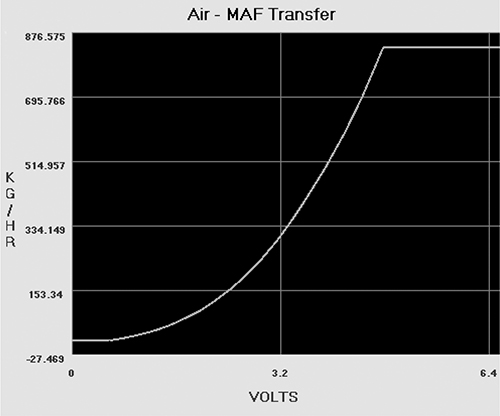
Figure 6-1: Ford MAF transfer graph
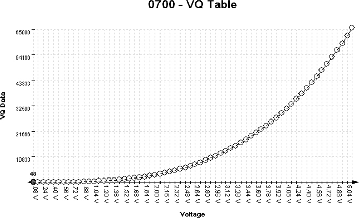
Figure 6-2: Nissan MAF VQ graph
Figures 6-2 through 6-6 show five different views of the same data. Figure 6-3 shows how the VQ curve pictured in Figure 6-2 would look in a hex editor.
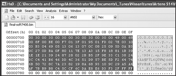
Figure 6-3: VQ table in HxD hex editor: 128 bytes or 64- to 16-bit words
Figures 6-4 and 6-5 show the VQ table in analyze.exe available from https://github.com/blundar/analyze.exe/. A simple visualization tool, analyze.exe colors cells based on their numeric value. You can select the precision of the data—for example, 1 = 8-bit byte, 2 = 16-bit word, and 4 = 32-bit long—and how many rows and columns you want present. This simple visual arrangement often makes it easier to identify what is code and what is data than it is when you’re using a hex editor, as in Figure 6-3.
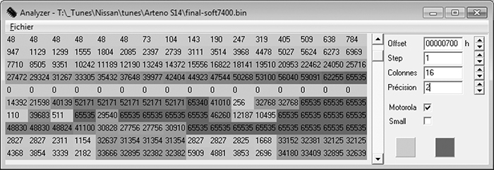
Figure 6-4: VQ table in analyze.exe: values from 48 to 65535 in first four rows of 16×16-bit values
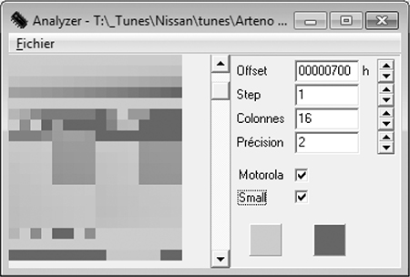
Figure 6-5: First four rows of 16x16-bit values
Look again at the first four rows of 16×16-bit values in Figures 6-4 and 6-5 shaded in analyze.exe. Notice how the smooth nonlinear curve in Figures 6-1 and 6-2 mimics the smooth nonlinear progression of values. Figure 6-6 shows the same values in a 64-column layout, so you can see the full gradient of the first four rows from Figure 6-5. No matter what type of vehicle you’re looking at, the overall data structures will be similar.
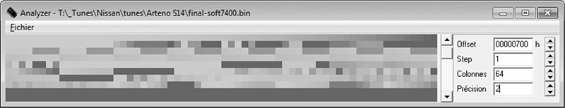
Figure 6-6: 64- to 16-bit words per row
Data visualization tools like hex editors or analyze.exe can also be useful when you don’t know the exact shape or pattern you are looking for. No matter what type of vehicle you’re looking at, data structures will have orders and patterns that are not typically seen in executable code. Figure 6-7 shows an example of the clear visual pattern of data in analyze.exe—gradually changing values and repetition should stand out.
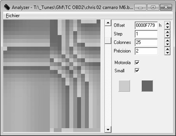
Figure 6-7: Patterns and gradual changes in table data appear in a 2002 Chevrolet Camaro ROM visualized with analyze.exe
On the other hand, when you look at code like that in Figure 6-8, there is a more random, chaotic appearance. (In Figures 6-7 and 6-8, precision is set to 2 because the microcontroller unit used is a 16-bit processor and it’s reasonable to assume that a good chunk of the data items will be 16-bit as well.)
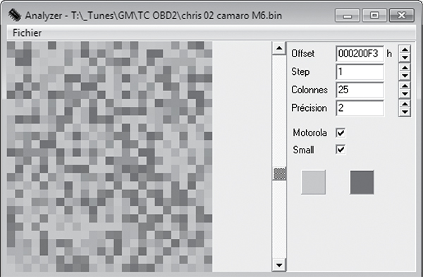
Figure 6-8: This random code doesn’t have the neat, orderly patterns that are present in most tables.
More to Learn from the MCU
Hopefully, these examples help connect knowledge of the table data you expect to find with their representation within a binary blob. Learning the capabilities of the microcontroller unit (MCU) used in a target system can shed light on the types of data to expect when looking over the binary data.
Generally, data representation formats are dictated by the hardware present. Knowing the size of registers on the MCU running the show can be a big help for identifying parameters. Most parameters tend to be the same size as or smaller than the registers of a given MCU. An 8-bit MCU, like a 68HC11, is likely to have lots of 8-bit data. It’s unusual to see mostly 4-byte, or 32-bit, unsigned long integers on an 8-bit MCU. While 16-bit data becomes more common on MCUs like the 68332, 32-bit data becomes the norm with MPC5xx Power Architecture MCUs and so on. It’s unusual to find floating-point data on an MCU that lacks a floating-point processor.
Comparing Bytes to Identify Parameters
It’s often possible to get multiple bins that’ll run on the same physical ECU. The more the better! Doing a simple compare in a hex editor will show which bytes differ between the files. It’s common—but not guaranteed—for code to remain unchanged while parameters change. If less than 5 percent of the files differ, it’s generally safe to assume that the differences are parameters. If you know what’s been changed functionally between the two bins and you know which bytes have changed, you have further clues to help correlate changes in the ROM with changes in parameters.
Figures 6-9 and 6-10 compare a 1996 V8 Mustang and a 1997 V6 Thunderbird, showing 6,667 differences out of 114,688 bytes. This is an extreme example of having the same code with different parameters, but there’s still only about a 5.8 percent difference compared to overall file size.
Most processors use an interrupt vector table defined by the processor being used. Referencing the processor’s data sheet will define the structure of interrupt routines, allowing you to quickly identify the interrupt handlers. Tracing interrupt pins on the processor to circuitry within the ECU to pins you can reference in a vehicle wiring diagram can help you identify code blocks used to service such hardware functions as fuel and spark control, crank and cam signal processing, and idle functions.
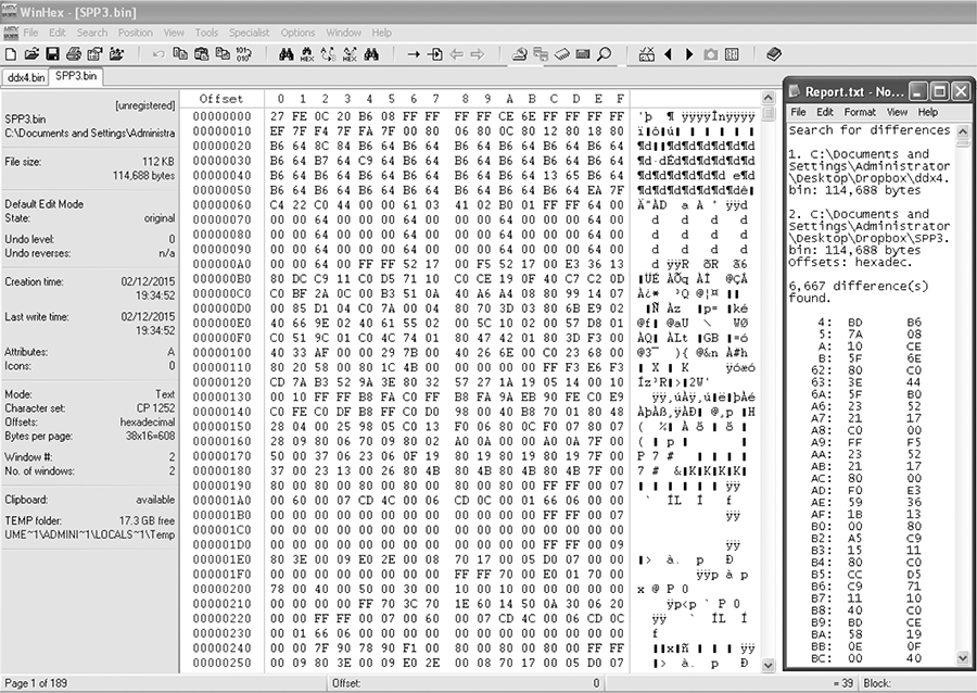
Figure 6-9: Comparison of a 1996 V8 Mustang (DXE2.bin) and a 1997 V6 Thunderbird (SPP3.bin)
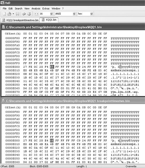
Figure 6-10: File compare function of the HxD hex editor
Identifying ROM Data with WinOLS
WinOLS is a popular commercial program for modifying bins. It combines a series of tools for calculating and updating checksums within a ROM with a set of tools for identifying tables. Figures 6-11 and 6-12 illustrate WinOLS in use.
If the ROM type is known, it has many templates that automatically identify configuration parameters. Most of the known built-in ROM types are geared toward Bosch Motronic ECUs. Templates and configurations can be saved, shared, and sold to enable users to make modifications to specific files with greater ease. WinOLS is arguably the most common software used for identifying interesting data within a ROM that doesn’t involve code analysis. It’s designed to facilitate rapid tuning changes to a controller.
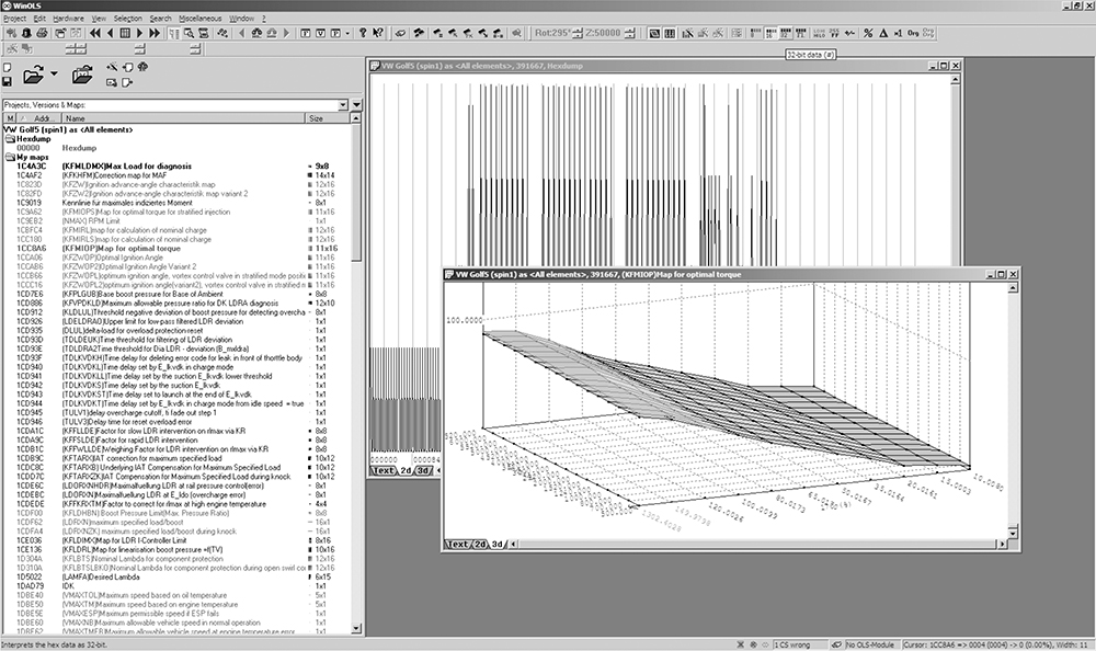
Figure 6-11: WinOLS supports 2D and 3D table views, as shown in these alternate views.
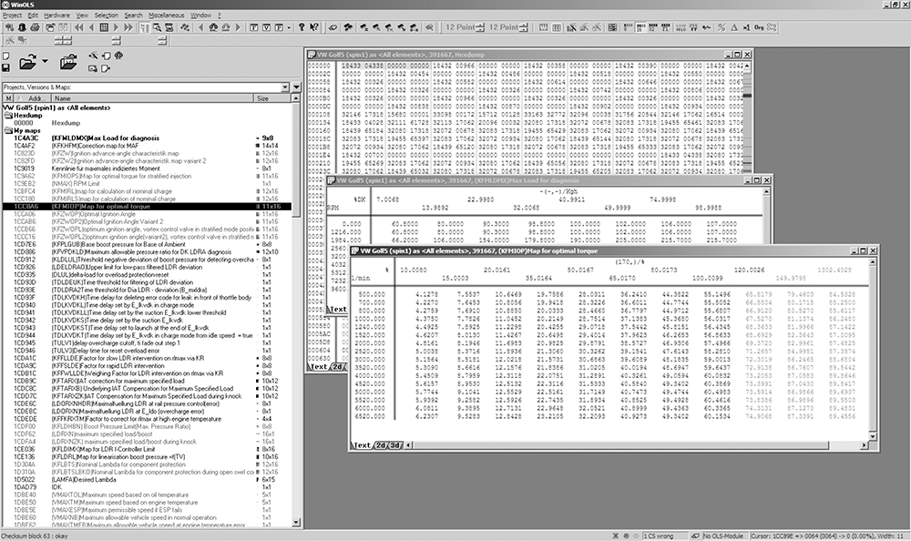
Figure 6-12: WinOLS being used on a 2006 Volkswagen 2.0Tsi ECU
Code Analysis
Code analysis can be a long, complicated task. If you’re starting from scratch, with no experience, it will likely take hundreds of hours to analyze a complex piece of code. Modern control units often have upward of a megabyte or two of code, which is a huge amount of code when you’re looking at it in assembly. An ECU from 1995 with 32 kilobytes (not megabytes) of code will have upward of 10,000 assembly instructions to sort out. Bottom line: do not underestimate how much work this approach will take. I’ll briefly introduce a few tools, but I don’t have the space to address the topic in sufficient depth for someone unfamiliar with the process. (After all, entire books have been written solely on code analysis.) Here, I’ll just talk through specific tools and methods particularly applicable to automotive embedded systems.
When analyzing a new target, first identify the architecture you’re working with. Knowing what processor executed the blob of binary will help you choose an appropriate software tool to further assist. If you can’t identify a processor based on the markings on the chip itself, search online for data sheets to identify it.
To analyze code, you might need to find a disassembler. A quick Google search reveals that there are lots of them out there. Some target a single architecture—for example, Dis51—and some are custom-written for automotive reverse engineering—for example, Dis66k. Others, like CATS dasm, IDA Pro, Hopper, dasmx, and objdump from the GNU Binary Utilities (binutils), target multiple processors. IDA Pro supports more embedded targets than just about any other program, but it’s also one of the most expensive disassemblers. GNU binutils also supports a pretty wide range of architectures, but the version included on most systems will be built only for the “native” architecture. Rebuilding binutils with all architectures enabled will open a few doors. Your budget and supported processors will determine which disassemblers are an option.
Bust out the disassembly tools and start trying to make sense of the mess, but as I warned earlier, this might take hundreds of hours. A divide-and-conquer mentality works best—focus on the smaller tasks rather than the project as a whole. If you obtained the binary by backdoor methods, you probably already took the ECU apart to identify the processor. If you cracked the J2534 programming routines, you might not have a clue what processor is running the show. In this case, you’re going to need to keep running it through a disassembler over and over using different settings until you get something that makes sense.
You’re looking for assembly code that disassembles cleanly, meaning that it looks like it makes logical sense. If you disassemble a binary for the wrong architecture or using the wrong settings, you’ll still see assembly instructions, but the assembler actions won’t make sense. Disassembly is a bit of an art, and it may take a little practice at seeing a “clean” assembler to get the hang of identifying when a dissassembler is providing the correct response, especially when nonexecutable tables and data are scattered among the code.
Here are some hints for making sense of disassembled code:
✵ OEMs love to patent stuff. If you can find the patents relevant to your system, you may end up with a guided tour of the code being disassembled. This is probably the most consistently available high-level procedural guide to help you understand the logic in an automotive computer. Patents usually lead production by at least one to two years, if not more.
✵ Look at any available software for manipulating the ECU at hand for insight into the structure and purpose of code segments. You can often infer a model of behavior from tables available to be modified in aftermarket software.
✵ Otherwise, start with a wiring diagram for the vehicle, and trace connections back through ECU circuitry to particular pins on the MCU. This should tell you which piece of MCU hardware handles which function. Cross reference the interrupt tables, or look for calls to service particular pieces of hardware in order to identify which piece(s) of code service that hardware function.
A plain, or old-style, disassembler will output very verbose text. Each individual instruction is parsed. Some disassemblers will attempt to mark areas referenced as data and void disassembling them. Other disassemblers need to be specifically told which areas are code and which areas are data.
A Plain Disassembler at Work
To see disassembly in action, we’ll look at a plain disassembly of a 1990 Nissan 300ZX Twin Turbo ROM. This ECU has a 28-pin external 27C256 EPROM, so it’s relatively easy to obtain its contents. This particular platform uses a HD6303 MCU, a derivative of the Motorola 6800 8-bit MCU that appears to be supported by the free disassembler DASMx (see http://www.16paws.com/ECU/DASMxx/DASMx.htm). DASMx comes with minimal instructions: to disassemble foo.bin, create a file, foo.sym, that describes which platform is in use, and then create an entry point in memory to place the image, symbols you know about, and so on. Time for a crash course in the architecture!
A critical point about the memory structure is that the MCU can address 65535 bytes (64KB). This information tells you what to expect when looking at the addresses in your binary blob. Further reading suggests that the interrupt vector table lies at the end of addressable memory, with the reset vector—where every processor starts after a reset—at 0xFFFE/0xFFFF. Assuming that the 32KB (0x7FFF hex) binary blob we have from reading the EPROM contains the interrupt vector table, we can figure out that the binary image needs to start at memory address 0x8000 for it to end at 0xFFFF (0xFFFF - 0x7FFF = 0x8000). It also helps to search online to see whether others are trying to do something similar. For example, the post at http://forum.nistune.com/viewtopic.php?f=2&t=417 is for a smaller 16KB binary based on settings for a 0xC000 entry point. The more legwork and research you do prior to actually invoking a disassembler, the more likely you are to get reasonable results.
Figure 6-13 shows the symbol table for the 300ZX binary. Next to each symbol is the memory address used by the firmware. These memory addresses can hold values such as incoming data from different physical pins on the chip or internal information, like timing.
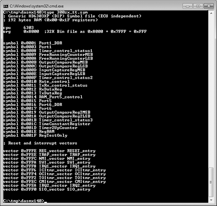
Figure 6-13: Symbol file for 32KB 300ZX binary disassembly with DASMx
We’ll use DASMx to disassemble the binary. As shown in Figure 6-14, DASMx reports a Hitachi 6303 MCU with a source file length, or size, of 32KB, which is 32768 bytes.
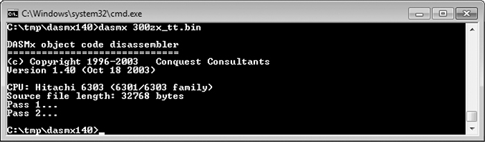
Figure 6-14: Running DASMx to disassemble 32KB 300ZX binary
Now cross your fingers and hope for a meaningful result!
The result is the vector table shown in Figure 6-15, which looks sane enough: all addresses are above the 0x8000 entry point specified. Notice that the reset vector (0xFFFE, RES-vector) has a pointer to the RESET_entry at 0xBE6D.
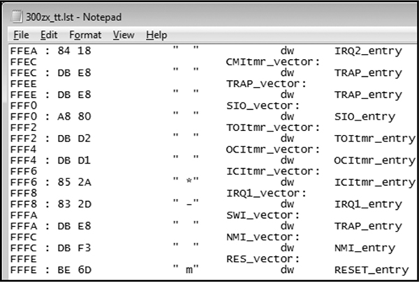
Figure 6-15: Disassembled vector table
We can disassemble the code at 0xBE6D for the reset vector, which is also the entry point for code. In Figure 6-16, we see a routine, RESET_entry, that looks like it wipes a chunk of RAM. This is a plausible part of the initial reset sequence because often when booting, firmware will initialize the data region to all 0s.
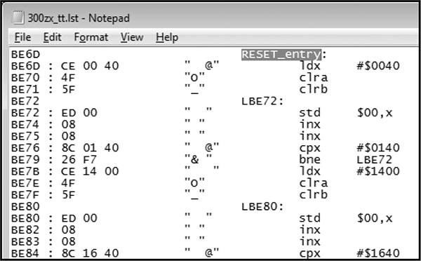
Figure 6-16: Reset vector disassembly
We’ve taken this example as far as obtaining a disassembled binary image and looking for basic sanity. Now, for the hard part: following the code, breaking it into routines, and trying to figure out how it works.
Interactive Disassemblers
As of this writing, IDA Pro is the most popular interactive disassembler available. It performs the same tasks as the simple disassembler just discussed, and more. Specifically, IDA Pro names registers and variables; once IDA Pro identifies and names a variable, or memory address—for instance, $FC50-RPM—it gives all references to that variable within the code a descriptive name rather than a less-recognizable plain hex address. IDA Pro also graphs code to visualize program flow.
One of the advantages of IDA Pro is that it’s programmable to allow additional opcodes for customizing automotive processors and plugins for further processing disassembled code (for example, decompiling assembly into higher language code); it also lets you use structs, unions, classes, and other user-defined data types.
Lastly, IDA Pro supports more embedded platforms out of the box than just about any other disassembler currently available.
You don’t necessarily need these functions to successfully analyze code, but they make things substantially easier. Figures 6-17 and 6-18 are screenshots from real code analysis with IDA Pro. Thanks to Matt Wallace for graciously posting these examples in a public forum.
The user in Figure 6-18 obtained Acura NSX ECU firmware through a combination of hardware-hacking approaches, took the code apart, analyzed it using IDA Pro, and rewrote it. Next, the user determined the necessary functions to log data from the ECU and alter its operation. The result allowed the user to use forced induction—that is, turbochargers and superchargers—with a factory computer; this would have been impossible without ECU modification.
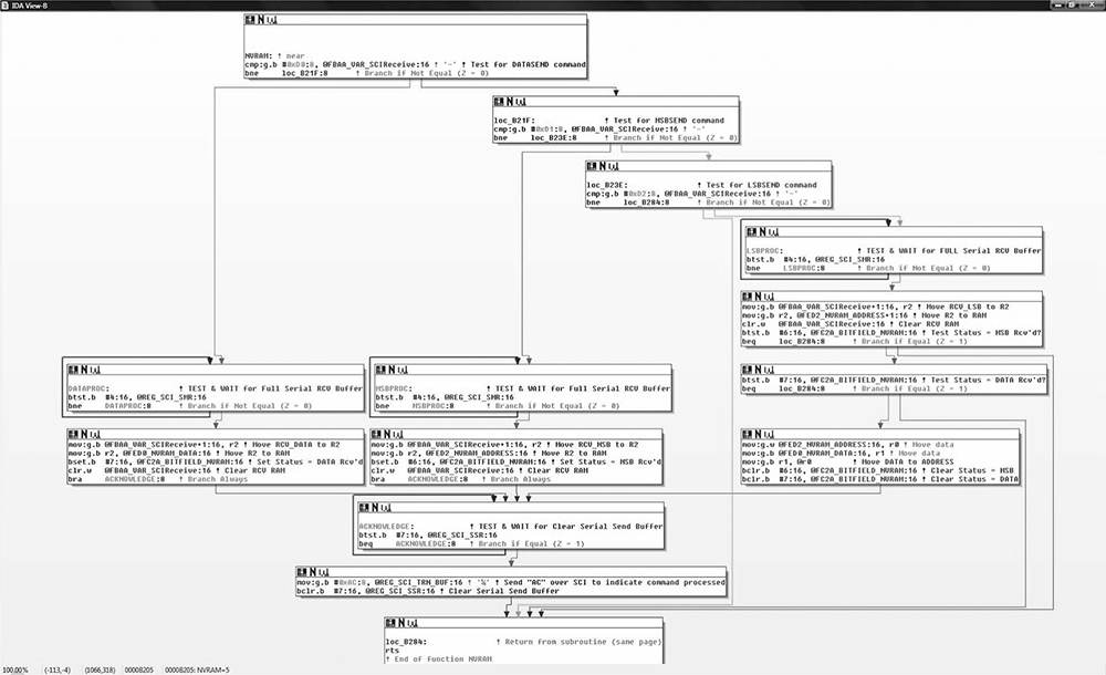
Figure 6-17: IDA diagram showing a custom-written routine for NVRAM real-time programming
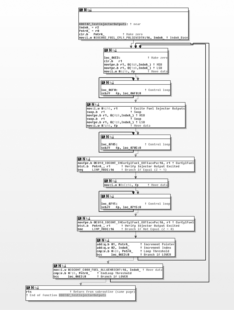
Figure 6-18: IDA diagram of code for checking fuel injectors on NSX ECU
Summary
Because hacking on the ECU often involves processors that are smaller than those used in more powerful modern devices, such as cell phones, the tools used for reversing the firmware differ for each target. By using a combination of techniques, such as data visualization to locate tables, and by reversing the firmware directly, you can identify the areas you’re interested in modifying. The methods discussed in this chapter are techniques commonly used by performance tuners to adjust how a vehicle handles fuel efficiency. All can be used to unlock features hidden in the code of your vehicle. We’ll look at performance tuning in more detail in Chapter 13.