DIY Solar Panels (2017)
Section # 3
Now to Create Your “WIP”
What are the Components?
Solar Cells- are the core element of a solar panel and these instructions apply to polycrystalline, monocrystalline, or multicrystaline solar cells universally as each are mechanically similar. The only difference of any kind you will experience during assembly, whether you are working with mono, poly, or multi-crystalline solar cells is the length of tabbing wire used to connect a pair of the solar cells. In order to connect two cells together, tabbing wire is used not only to physically bond them, it also conducts the excited electrons (or current) on their path through the solar panel.
What electrons you ask? A brief refresher or introductions as it were, to explain how a solar cell generates electricity when exposed to sunlight is in order. It all begins about 93-million miles away on the Sun which has a surface temperature of over 5,000°C and a core temperature some 2,700 times the surface temperature. The core is intensely radioactive and produces light-energy known as photons that have no mass, only huge amounts of energy and momentum. It may take a million years for a single photon to travel from the Sun’s core, to the surface where it is propelled into outer space with an approximate speed of 670,000 miles per-hour². In about eight minutes the photons cover the nearly 93-million miles of space to reach Earth but some photons will be deflected in outer-space, the remainder make contact with the atmosphere and on to the planet’s surface. When the sun warms your skin on a sunny day you are feeling the photons strike your exposed skin creating the warmth that is the source for much of the life here on Earth. When photons strike a solar cell as illustrated in the graphic on the previous page, they can glance off, pass through, or make a perpendicular, head-on impact. It is the perpendicular impact, or anything reasonably close to it that creates the excited electrons leading eventually to electricity generation. How can thephotons generate electricity? This is a complicated scientific principle known as the “photovoltaic effect” which I will briefly describe, only for familiarity. I do suggest further reading from other sources for greater detail.
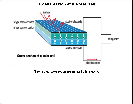
Refer to the cross section of a solar cell on page 31, and note the blue surface of the solar cell being struck by the photons as indicated by the red arrows. Photons will do one of three things when striking a solar cell; they can bounce off, a glancing shot so to speak, they can penetrate completely, passing through the solar cell and striking the ground or whatever is behind the solar module, or lastly, can pass into the solar cell causing the desired chain reaction that the solar cells are poised to perform. A solar cell is really a sandwich made from two layers of silicon serving as the bread, and a hollow area in the middle where the electricity is created. The layers of silicon on their own will simply allow the photons to pass through and so, each of the layers is treated with a chemical, or “doped” as it is called in reference material. In essence the silicon wafers must be treated in order to provide them with “semiconducting” properties. According to Whatis.techtarget.com a semiconductor is any material usually a solid chemical or compound that can conduct electricity under some conditions but not others. As you will see, the two halves of our silicon sandwich will each be “doped” with a different agent to achieve a specific result. As you probably guessed, many doping agents are used to achieve different results giving silicon a broad applicability in electronics. Let’s get into how the silicon is “doped” in order to work as they do…
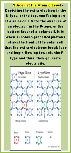
The side of the solar cell facing the sun is the “negative” side of the cell and is called, “n-layer”, or “n-type” in our graphic. This negative side of the solar cell is “doped” with phosphorus because at the atomic level, phosphorus has the unique trait of containing an extra electron in its atomic structure. This extra electron sits at rest in the atoms structure inside the “doped” solar cell until sunshine-propelled photons collide with the “n-layer” at the proper angle. Photons are comprised of energy and momentum from the sun’s radiation and thus, upon colliding with the “n-layer”, they release the stored energy and momentum of which they are made. In response to being bombarded with these balls of energy, the atoms become excited from the sudden and vibrant radiation energy and the extra negatively charged electrons get bounced free from the phosphorus-doped N-layer of silicon. The chain reaction starts on the sun-facing side of the solar cell but once the electrons contained within this section become excited, broken free from the valence that previously held them, they then perform the next required step which is passing through the P/N Junction. This junction is the area in the center of our sandwich example and it is depicted in our graphic as simply a white line. However, it is a one-way street for the electrons because once free, the flow of electrons around the circuit begins and represents the formation of “current”, or electricity. The importance of the P-layer should not be understated because without the vacant electrons in the boron-doped silicon molecules, there would be no flow of electrons, hence, no electrical generation. Once the flow of electrons is started, a path is made for them to travel from cell to cell by way of the tabbing wire which we will discuss next. I did not want to make this an overly technical discussion because once we start talking about atomic structures; I suspect some readers may have skipped a few pages in hopes of bypassing a science lecture. I think we covered the most pressing science behind the photovoltaic effect which you are probably interested in if you have this in your line of sight either printed or electronic versions. Technology is advancing in photovoltaics on a quest to achieve greater efficiency, the highest possible rate of conversion of sunlight into electricity. Experimental doping agents have shown interesting promise and thus, in order to follow the developments, my Solar Tech DIY Facebook blog will include discussions about emerging technologies in the field of Photovoltaics.
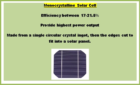
Upon close visual inspection you will notice that solar cells look different, seemingly all of them have some different variation on color and line patterns, irregular shapes visible on the surface although, some don’t, and some are solid in color. We touched on the reason for the color differences earlier when discussing the origins of the monocrystalline verses polycrystalline solar cells. If you recall, monocrystalline solar cells are cut from a single monocrystalline silicon ingot as seen in the page margin to the left. The ingots are grown through the Czochralski process, a method of creating large single crystal ingots for use in semiconducting. The silicon required for this process is very clean and pure and so the resulting solar cells cut as wafers from these ingots will have a consistent coloring shade and appearance.
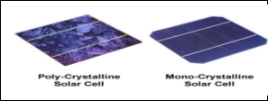
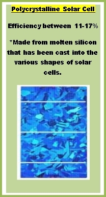
Contrast the consistent appearance of monocrystalline solar cells with the haphazard and random patterns discernable on polycrystalline solar cells, the difference is obvious in the photo above.
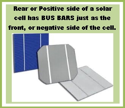
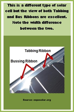
In light of the visual difference, it is easy to distinguish between the two types. The random patterns of the polycrystalline come from the molten origins that mixed several smaller crystals or even crystallites which upon cooling retained some of their individuality in appearance anyhow. While the resulting polycrystalline ingot can be as much as 99.9% pure, the solar cells cut from these ingots are slightly less capable than their monocrystalline cousins. One visual cue consistent with all types of solar cells is the presence of tiny wires running horizontally across the sun-facing side as well as a pair, or even a trio of white bands running perpendicular to the tiny wires. As seen in the photo above and to the left, those white bands are known as “bus bars” onto which you would solder the tabbing wire that not only connects the solar cells together, but also serves as the conduit for the flowing electrons. The bus bars are also on the back, or positive side of the solar cells, in certain versions the “bar” is replaced by small “tabs”. Whether bus bar or bus tab, they function the same and are joined to the solar cell in the same way. The tiny wires that appear as thin white lines running horizontally across the negative, sun-facing side of the solar cell are called “fingers”, and are added to the silicon wafer during the manufacturing process. They are necessary for the efficient movement of electrons through the entire surface the solar cell once the sun is out and spewing photons for the solar cells to absorb. To end the conversation about solar cells, I want to touch on the common blue color present in a great many versions and types of solar cells. The technical details are beyond the scope of this eBook but suffice it to say that a silicon nitride antireflective coating produces that blue tint common in solar cells. The silicon nitride antireflective coating is present to optimize specific wavelengths on the color spectrum, which helps capture as much light-energy as possible.
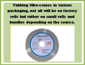
Tabbing Wire - is also known as Interconnect Wire and it provides two functions. First, it serves to physically join the solar cells together thus providing structure and sturdiness. Second, it provides the path and conveyance for the electrons set in motion once photons begin knocking them into motion within the solar cell. Different sized tabbing wire is available and for this type of project, I recommend (.15 x 2mm) which is an ideal width for most of the solar cell types we will be working with.
Tabbing wire is made out of flat copper wire that is then coated with tin, or a tin alloy that when heated becomes liquid and helps the wire bond to the bus bar. Some tabbing wire suppliers may suggest that use of rosin core solder is unnecessary due to the presence of the tin coating over the tabbing wire. Disregard such advice since the solder gun tip needs rosin core solder on it simply to convey heat, it doesn’t matter if the tabbing wire is pre-tinned. When the heated solder tip (that is lightly coated with rosin core solder) touches the tabbing wire, the tin coating liquefies. Heat, liquid tin, and a clean bus bar make a great mating surface for tabbing wire to bond onto a solar cell. When preparing to solder tabbing wire, pre-heat the solder gun and apply just a small dab of rosin core solder with each application of a tabbing wire. This will ensure consistent heat for each tabbing wire portion, the result being a uniform performance throughout the entire string of solar cells.
Heat discussion again - the temperature inside a solar panel during summer months can easily exceed 175° as I have personally measured. You will experience how quickly solar cells not only collect, but retain heat as you gingerly handle newly completed solar cell “pairs” while testing them in full sun. It takes but a few moments to thoroughly test a “pair” because you are only measuring volts, and amps, requiring one switch turn and simultaneous cable swap. When successful (which will be increasingly more consistent as you practice, but hopefully right off the bat) there is the obligatory self-celebration, a couple fist-pumps, an appreciative look towards the heavens, followed by curses when you burn all of the flesh making contact with the solar cells you were just fist-pumping about. Now multiply the heat by whatever number of little cousin-solar cells that will be encapsulated along with the two that just charred your flesh in a solar panel, under glass, perpendicular to the sun, all day while you are hunkered down in the root cellar hoping there isn’t anything else down there similarly escaping the heat. Unfortunately the heat has a dampening effect on solar panel performance because of some complicated phenomenon that exceeds the scope of this manual. While complicated, I can provide an overview in generic terms on the next couple pages.
Solar panels generate electricity basically by reacting to stimuli from an external source, the sun. Specifically, photons from the sun that collide with our phosphorus-doped N-layer of silicon wafer, the top half of our silicon sandwich example. Photons are comprised of energy and thus, when they collide with atoms inside the solar cell that have excess electrons, they knock the electrons lose. The dislodged electron conducts a frantic search for a new atom to call home, one that is in need of an electron. This process is repeated many millions of times over within the confines of a solar cell. Freed electrons bounce and dance down through the P/N Junction inside a solar cell and in doing so are create the electricity attributed to solar cells.
Vibration is created when photons strike atoms inside a solar cell, but there is another source of vibration, heat. Most of us have seen water boil; we have seen evidence of heat making molecules move so fast that the resulting collisions are visible to the naked eye in the form of churning water. Solar panels need to be perpendicular to the sun for the best efficiency which translates to a significant exposure to high internal temperatures. Think of your sun glasses sitting on the dashboard while you shopped, even for thirty minutes, those glasses are going to be too hot to immediately put on if the sun was shining directly on them. A solar panel that is mounted perpendicular to the sun and is filled with dark colored solar cells will generate high internal temperatures. The byproduct of this intense heat is vibration at the molecular level, not visible like the boiling water molecules, but present nonetheless.
Add to the equation triple-digit ambient air temperatures and the resulting temperature inside the solar panel becomes a problem. Excessive vibration within the solar cell environment causes a slowdown of electron movement as they must now struggle against more movement than normal. The cumulative effect of this added vibration from the various sources is that the electrons get bogged down and have difficulty moving freely within the P/N Junction. If movement is restricted to the point whereby the electrons cannot join the flow, or current, they die out having expended energy uselessly while attempting to join the flow of electricity. The heat may not stop the flow entirely but the decline in power output will be noticeable.
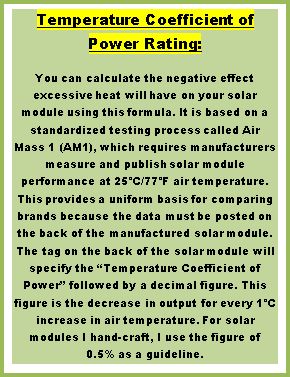
Stated another way, prior to the sun rays striking a solar cell it is in a state of rest to include the electrons contained within the layers of silicon that comprise our solar cell. The electrons at rest represent a low-energy existence at the time and the sun’s photons represent high-energy. Without oversimplifying the process, the difference between energy levels while the electrons are at rest, and the energy contained within the inbound photons, represent the electrical potential within a given solar cell. It seems unnatural that a hot, desert environment with a lot of sunshine may not produce as much energy as a clear, cold, but sunny day in an environment other than a desert but as described it is true. This brings up the ideal time to segue into a brief conversation about how solar panels are rated for performance or output. There must be a uniform standard for establishing the wattage performance on solar modules (another name for solar panels) and so, for uniformity, all solar modules are tested by the manufacturers at a consistent air temperature of 25°C/77°F to simulate exterior conditions. Then the module or solar cell is exposed to lamps powerful enough to mimic the 1,000 Watts per meter squared (1,000 W/m²) typical of noon time sun and output is measured. Manufactured solar modules have ratings called “temperature coefficient of power” that tells the reader how each 1°C temperature increase will negatively affect the performance of a given solar module, for example, the number might be 0.5%. The first step in this process is to establish the difference between ideal laboratory test conditions verses real world conditions where the solar module is deployed. For example, if a solar module was being observed for temperature related performance issues at 85°C/185°F, it would represent 60°C OVER the baseline Celsius testing figure of 25°C. To quantify the decline in output we need only multiply 60°C by the temperature coefficient of power rating of 0.5% to arrive at 0.3 (60 x 0.5 = 0.3). The next step is to multiply 0.3 by the Designer Wattage provided by the manufacturer (100 Watts for this example) to arrive at the number of Watts that will NOT be generated because of excessive heat.

The potential loss of generating capacity at an internal temperature of 185°F is 30 Watts, or 30% of total generating capacity.
If we are looking for a number value that reflects a percentage we must convert our answer into the proper format. Remember from math lessons that in order to multiply any number by a percentage, you must first reduce the percentage into a whole number, one that can be multiplied. Simply moving the decimal point to the left by two spaces is the equivalent of having multiplied the percentage number by 1/100, the required step in mathematics to convert a percentage into a whole number. Our new mathematically acceptable number for this calculation is 0.3 (zero doesn’t need to be there, just a visual place holder so attention is drawn to the decimal point).
If you are good at performing match calculations in your head, the 100-Watt solar panel is ideal to work with for this example since we need to find a numeric value for the 30% performance decline we have identified due to excess heat. If we multiply 30% by the “designer wattage” of 100 Watts, we will reveal at the quantity of watts that will NOT be generated due to the heat. When we multiply the 100-Watt solar panel by the temperature coefficient power rating number of 0.3, it equals 30-Watts, so the excessive heat will deprive the solar panel of 30-Watts of generating capacity.
The last thing I want you to walk away thinking is that solar modules (solar panels) up on your roof will simply get too hot to work at all. This is NOT the case but knowledge is power, and being aware that heat has an effect on solar panel power output can assist you in taking the appropriate steps to mitigate surprise heat waves. Simply knowing heat reduces the amount of electricity your solar array can gather should prepare you for this eventuality because there are a few steps to take. First and foremost is to conserve the existing battery power when days are exceptionally hot. This might prove difficult in light of the comfort electric fans bring to a hot room, but if not conserving fan use, look elsewhere for devices that can afford to be shut down until the next day in order to conserve power. Adding solar panels to compensate is one option especially if heat is a regular presence where panels are deployed.
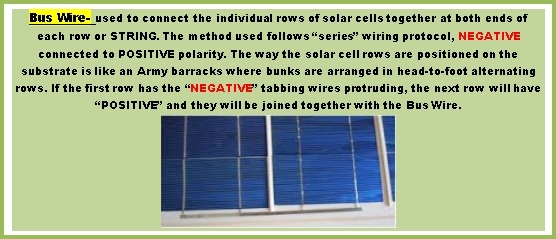
Bus Wire - is very similar to tabbing wire with the same structure and function; it is simply much heavier gauge. Bus wire carries the current generated by the solar cell STRINGS and delivers it to the junction box. There will always be two bus wire leads coming out of a solar panel, one positive, the other negative, which then connect to the corresponding output leads within the junction box. In addition to carrying current the bus wire provides infrastructure for the STRINGS within a given solar panel until such time as encapsulation permanently secures the internal components. The typical solar panel or solar module upon close inspection has four rows of solar cells running from the bottom of the solar module, to the top. If you look at the ends of the four rows, you will see how the rows are connected to each other at both ends of the solar panel, I have attached a photo to the left. The photo depicts only two rows while a typical solar module would have four but the photo serves an excellent example of what is known as an “end run” since you guessed right, and it is the end of a run of solar cells.
When you get to the step where bus wire is being used, the solar module is nearly completed. You will have utilized tabbing wire to connect the individual solar cells, and now the bus wire is used to connect the rows, or STRINGS of solar cells physically together, but also to provide a conduit through which the electrons (current) can flow not between solar cells as the tabbing wire provides, but between ROWS of solar cells. The flow of current follows a path around the rows, very orderly, and the bus ribbon is the path the current flows through as it makes its way into the battery bank. We will cover more on the specifics of soldering with bus wire but you will find it one of the easiest elements to work with due to its size, sturdiness, and rigidity. In addition to connecting the rows of solar cells inside the structure of the solar module, one bus ribbon for each, the positive and negative leads that must be accessible on the back of the solar module. It is these leads made from bus ribbon that physically connect each solar module to the photovoltaic cables that allow for quick connecting to other solar modules, or the leads are tied into “project boxes” or junction boxes where other types of cabling may be connected if not utilizing special photovoltaic connectors.
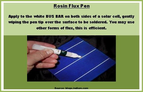
Rosin Flux - in a pen, like a magic marker, used to coat the silver BUS BARS on both sides of the solar cell prior to soldering the tabbing wire to the solar cell. You may use other forms of flux such as the gel that can be brushed on, but the pen variant is so efficient that it is hard to justify NOT using a Rosin Flux Pen as depicted on the “tools” chapter. According to Wikipedia, the word “flux” is derived from the Latin word, “fluxus” and translates into the word “flow” in the English language, and indeed that is one of the functions the flux performs after it is applied to the BUS BAR. In fact, the flux cleans off any impurities that might otherwise have a negative effect on the bond between the solar cell and the tabbing BUS BAR. Additionally, the flux aids in the process of heat transference from the soldering gun tip, to the tabbing wire you are soldering. It is non-negotiable, you MUST use a flux of some type or you will have a very difficult time achieving a solder that is mechanically sound and will conduct electricity.