Solar Electricity Handbook 2011: A Simple Practical Guide to Solar Energy - Designing and Installing Photovoltaic Solar Electric Systems - Michael Boxwell (2011)
Detailed Design
By now, you know what components you are going to use for your solar project. The next step is to work on your detailed design: effectively, a picture of what you want to build. Even for simple projects, it makes sense to draw up a diagram before installation.
The benefits of drawing a wiring diagram are numerous:
· It ensures that nothing has been overlooked
· It will assist in the cable sizing process
· It helps ensure nothing gets forgotten in the installation (especially where there is a group of people working together on site)
· It provides useful documentation for maintaining the system in the future
The wiring diagram will be different for each installation and will vary depending on what components are used. Read the product documentation for each component for information on how it must be wired.
If you have not yet chosen your exact components at this stage, draw a general diagram but make sure that you flesh this out into a detailed document before the installation goes ahead.

A sample wiring diagram for a simple stand-alone lighting system
When drawing up your wiring diagrams, you will need to remember the following:
Safety is designed in
It is easy to forget that solar energy can be dangerous. We are working with electricity and whilst any individual component may only be low-voltage, some of the currents involved can be quite significant. Furthermore, connecting multiple solar panels or batteries together in series can very quickly create a high voltage. It is therefore important that safety be taken into account during the detailed design phase of the project, as well as during installation.
When designing the system, ask yourself this question:
“What’s the worst that can happen?”
Solar energy systems are relatively straightforward and the design of all the components you will use will keep risks to an absolute minimum. Nevertheless, there are potential risks. If you are aware of these risks, you can take steps to eradicate them in your design.
What is the worst that can happen with a solar installation?
With solar energy, we will be working in a few risk areas: DC electrics from the solar array, high currents from batteries, AC electrics if you are using an inverter, and high temperatures from the solar panels themselves.
Each of these risk areas can pose problems, both in isolation and when combined. It is worth considering these risks to ensure that you can design out as many of them as possible.
Grounding your electrics
Except for a very small system, such as rigging up a light in a shed, a solar energy system should always be earthed (grounded). This means running a wire from a negative terminal to an earthing rod (known as a grounding rod in North America) that is rammed into the ground.
An earthing rod (grounding rod) is a 1m (3 foot) long metal pole, typically made of copper. They are available from all electrical wholesalers and builders’ merchants.
Connections to a ground prevent build-up of static electricity and can help prevent contact with high voltages if the circuit gets damaged.
If you are connecting a solar array to a home, you should always include a ground connection from the solar array itself. Whilst it is optional in other cases, it is always a good idea to include a ground from a solar array, where the array is capable of generating more than 200 watts. You must also earth the battery bank, as they are capable of delivering very high currents.
If you are using both AC electrics and DC electrics in your system, you must always have a separate ground for each system.
Grounding a system where you cannot connect to the ground
There may be instances where you are building a system where no connection to the ground is possible. For instance, a portable solar charging unit that can be carried anywhere, or a solar powered boat.
Typically, these designs are very small, using only DC electrics and running only a few amps of current. If your solar array is less than 100 watts, your system runs at 12 volts and you are drawing less than 10 amps of current, you are unlikely to need a common earth for all your components.
For larger systems, a ground plane is often used. A ground plane is a high-capacity cable connected to the negative pole on the battery, to which every other component requiring a ground is also connected. A thick, heavy-duty battery interconnection cable is often used as a ground plane cable, with thinner wires connecting to this ground plane cable from every other component requiring an earth.
As an alternative to a high-capacity cable, depending on what you are installing your solar system on, you can use a metal frame as the common ground for your system. In standard car electrics, for example, the ground plane is the car body itself.
DC Electrics
Direct current electricity typically runs at relatively low voltages: we are all familiar with AA batteries and low-voltage transformers used for charging up devices such as mobile phones. We know that if we touch the positive and negative nodes on an AA battery we are not going to electrocute ourselves.
However, direct current electricity can be extremely dangerous, even at comparatively low voltages. Around the world, a small number of people are killed every year by licking 9-volt batteries, because of the electric jolt they receive. Scale that up to an industrial grade heavy-duty 12-volt traction battery, capable of delivering over 1,000 amps of current, or a solar array capable of producing hundreds of volts on an open circuit, and it is easy to see that there is a real risk involved with DC electrics.
If you are electrocuted with AC power, the alternating current means that whilst the shock can be fatal, the most likely outcome is that you will be thrown back and let go. If you are electrocuted with DC power, there is a constant charge running through you. This means you cannot let go. If you are electrocuted with very high current DC, the injury is more likely to be fatal than a similar shock with AC power.
Because of the low current from a single solar panel, you are unlikely to notice any jolt if you short-circuit the panel and your fingers get in the way. However, wire up multiple solar panels together and it is a different story. Four solar panels connected in series produce a nominal 48 volts. The peak voltage is nearer 80-100 volts. At this level, a shock could prove fatal for a young child or an elderly person.
The current thinking with grid-tie solar systems is to connect many solar panels together in series, creating a very high-voltage DC circuit. Whilst there are some (small) efficiency benefits of running the system at very high voltage, there are risks as well, both during the installation and the ongoing maintenance of the system.
There are issues with the 12-volt batteries too. Industrial grade, heavy-duty batteries can easily deliver a charge of 1,000 amps for a short period. Short out a battery with a spanner and it will be red hot in just a few seconds. In fact, the current delivery is so great it is possible to weld metal using a single 12-volt battery.
The big risk with DC electrics is electrocuting yourself (or somebody else) or causing a short circuit, which in turn could cause a fire. Solar panels generate electricity all the time, often including a small current at night, and cannot simply be switched off. Therefore, there need to be manual DC circuit breakers (also called isolation switches) to isolate the solar panels from the rest of the circuit, plus a good ground and a ground fault protection system to automatically switch off the system should a short circuit occur.
If your system is running at a high voltage, you may want to consider multiple DC circuit breakers/ isolation switches between individual solar panels. This means that, as well as shutting off the overall circuit, you can reduce the voltage of the solar array down to that of a single panel or a small group of panels. This can be of benefit when maintaining the solar array, or in the case of an emergency.
A short circuit in a solar array can happen for many reasons. Sometimes it is because of a mistake during installation, but it can also occur as a result of general wear and tear (especially with installations where the tilt of the solar panels is adjusted regularly) or as a result of animal damage such as bird mess corroding cables or junction boxes, or a fox chewing through a cable.
Short circuits can also occur where you are using unsuitable cabling. Solar interconnection cabling is resistant to UV rays and high temperatures, and the shielding is usually reinforced to reduce the risk of animal damage. Always use solar interconnection cabling for wiring your array and for the cabling between the array and your solar controller or inverter.
When a short circuit does occur, there is often not a complete loss of power. Instead, power generation drops as resistance builds up. There is a build-up of heat at the point of failure. If you have a ground fault protection system such as an RCD or GFI in place, the system should switch itself off automatically at this point, before any further damage is caused.
If you do not have a ground fault protection system in place, the heat build-up can become quite intense, in some cases as high as several hundred degrees. There have been documented instances where this heat build-up has started a fire.
If a fire does break out, you need to be able to isolate the system as quickly as possible. Because a solar array cannot be switched off (it always generates power whenever there is light) there have been cases where the fire brigade have not been able to put out a fire generated by a fault in a solar array because there has been no way of switching it off. Isolating the solar array quickly, using a DC circuit breaker, resolves this problem.
However, remember that, even if you isolate the solar array, you are still generating power within the solar array. If you have many solar panels, the voltage and the current can still be quite considerable. The ability to shut down the array by fitting DC circuit breakers within the array can significantly reduce this power, rendering the system far safer if there is an emergency.
AC electrics
AC electrical safety is the same as household electrical safety. It is high-voltage and in many countries you are not allowed to work with it unless you are suitably qualified.
You will need to install two AC isolation switches: one switch between the inverter and the distribution panel to isolate the solar system completely, and one switch between your grid-feed and your distribution panel to isolate your system from the grid if you are running a grid-tie system.
If you are planning a grid-tie installation, you will need to speak with your electricity supplier, as there will often be additional requirements that you will need to incorporate. Your inverter will need to be a specific grid-tie system that switches off in the case of a grid power cut. This ensures that power is not fed back into the grid from your solar system in the case of a power failure, which could otherwise prove fatal for an engineer working on restoring power.
High temperatures
We have already touched on the risk of high temperatures with a solar array. Solar panels are black and face the sun: they can therefore get very hot on a warm day. It may not be hot enough to fry an egg, but in many climates it can certainly be hot enough to burn skin.
So make sure your solar array is installed in a place where it cannot be touched by curious children. If the solar panels are close to the ground, make sure there is some protection to keep people away from it.
The high temperatures become more of a problem if there is a fault within the solar array or with the wires running between solar panels. If a cable or a solar panel becomes damaged, there can be significant heat build-up. As already mentioned, this heat build-up can lead to a fire.
A residual current device (RCD), otherwise known as a ground fault interrupter (GFI) should avert this problem, allowing you to investigate the issue before significant damage occurs. However, manual DC circuit breakers should also be installed in order to override the system in case of an emergency.
Think safety
That is the end of the safety lecture for now. I will touch on safety again when we come to installation, but for now, please remember that safety does not happen by accident. Consider the safety aspects when you are designing your system and you will end up with a safe system. The additional cost of a few AC and DC circuit breakers, an earthing rod/ grounding rod, an RCD/ GFI and getting the right cables is not going to break the bank. It is money well worth spending.
Solar array design
All solar panels in an array must face in the same direction. This ensures that each cell receives the same amount of light, which is important for optimum power production.
Sometimes, you may want to install solar panels in different locations, such as on two different pitches of roof. In this instance, you need to keep the two banks of solar panels separate, running them as two separate arrays, either by feeding them into an inverter or controller that can handle more than one solar input, or by feeding them into two separate inverters or controllers.
If you wish to mix and match different sizes of solar panel, you will also need to set these up in separate arrays and wire these separately, either using an inverter or controller that can handle more than one solar input, or using two separate inverters or controllers.
If you are designing a grid-tie system, where you are considering different sizes or orientations of solar panels, you should seriously consider a micro-inverter system where each solar panel has its own inverter.
Solar array design - stand-alone systems
If you have more than one solar panel and you are running your solar electric system at 12 volts, then you will need to wire your panels together in parallel in order to increase your capacity without increasing the overall voltage.
If you are running your solar electric system at higher voltages, you either need to buy higher-voltage solar panels, or you will need more than one solar panel, wired in series to increase the voltage of the solar panels to the voltage of your overall system:
· For a 24-volt system, you have the choice of using 24-volt solar panels, or two 12-volt solar panels connected in series
· For a 48-volt system, you can use one 48-volt solar panel, two 24-volt solar panels connected in series, or four 12-volt solar panels connected in series
Once you have reached the voltage that you want, you can then run the panels both in series and in parallel, connecting strings of panels together in series to reach your desired voltage, and then connecting multiple strings together in parallel to increase your capacity:
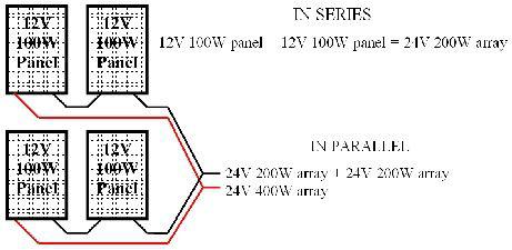
A sample diagram of a 24-volt array where two sets of two 12-volt solar panels are connected in series in order to create a 24-volt array and the two arrays are then connected in parallel to create a more powerful 24-volt array.
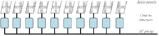
Solar array design - grid-tie systems with micro-inverters
If you are designing a grid-tie system and using micro-inverters, your design is extremely simple. Each solar panel becomes a self-sufficient solar energy system, each feeding power into its own micro-inverter. The micro-inverters convert the energy to AC and feed it into the main AC circuit.
Solar array design - grid-tie systems with a single inverter
If you are designing a grid-tie system with a single inverter, you will typically be connecting all your solar panels in series and then feeding this high-voltage DC power into an inverter.
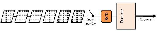
A simplified block diagram of a typical grid-tie system using a single inverter. The residual current device (RCD) provides ground fault protection. In the United States, an RCD is known as a ground fault interrupter (GFI)
Because of the very high DC voltages involved, additional safeguards are necessary. The solar array must always be grounded, there must be a DC circuit breaker (also known as an isolation switch) installed between the solar array and the inverter and there must be a DC residual current device/ ground fault interrupter installed to shut down the solar array in the case of a short circuit.
In the diagram below, there are sixteen solar panels connected in series. Assuming each solar panel produces a 12-volt output, this system will run at a nominal 192 volts, with a peak power in the region of 320 volts and an open circuit voltage of 416 volts.
Because of the very high voltages, I have decided to install additional DC circuit breakers in the middle of the solar array in order to reduce the voltage within the array if I switch them off. This makes the system safer during maintenance and can reduce the risk of fire or electrocution in case of an emergency.
The diagram shows two AC isolation switches: one switch between the inverter and the distribution panel to isolate the solar system completely from your house and one switch to isolate your building from the grid.
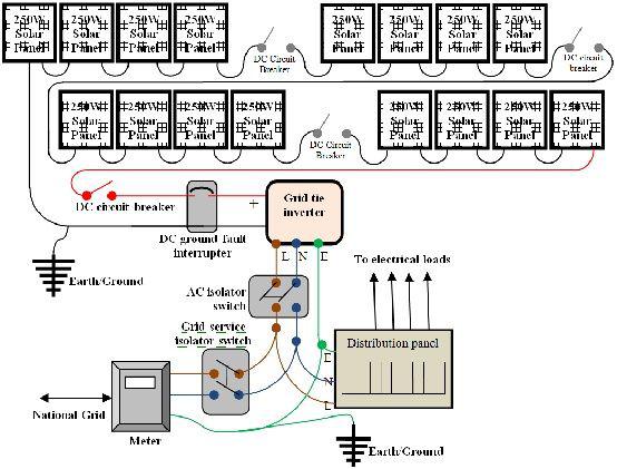
Above: A sample block diagram for a grid-tie system
In the United States, you are not allowed to have a grid-tie solar energy system where any part of that system has the potential to run at over 600 volts. This means that the open voltage of your solar array must be less than 600 volts. In general, this means that you will not want to connect more than twenty 12-volt solar panels or ten 24-volt solar panels in series, in order to ensure that you stay well below this level.
In Europe, it is advisable that your open circuit voltage remains under 1,000 volts. In general, this means that you will not want to connect more than thirty 12-volt solar panels, or fifteen 24-volt solar panels in series.
If you are running close to this limit, there are three options, which I have listed in order of preference:
· Install a micro-inverter system
· Install a multi-string system, either using an inverter that handles more than one solar feed, or by using two separate inverters
· Wire your solar panels in a parallel/series hybrid
Batteries
Batteries are wired in a similar way to your solar array. You can wire up multiple 12-volt batteries in parallel to build a 12-volt system with higher energy capacity, or you can wire multiple batteries in series to build a higher-voltage system.
When wiring batteries together in parallel, it is important to wire them up so that you take the positive connection off the first battery in the bank and the negative connection off the last battery in the bank.
This ensures equal energy drain and charging across the entire battery bank. If you use the same battery in the bank for negative and positive connections to the controller and inverter, you drain this first battery faster than the rest of the batteries in the bank. The first battery also gets the biggest recharge from the solar array.
This shortens the life of the battery and means all the batteries in the bank end up out of balance. Other batteries in the bank never get fully charged by the solar array, as the first battery will report being fully charged first and the controller will then switch the power off rather than continuing to charge the rest of the batteries in the bank. The result is that the batteries end up with a shorter lifespan.
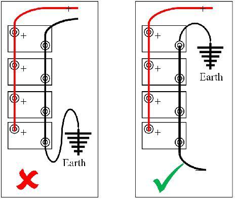
How to wire batteries in parallel: the diagram on the left, where power feed for both positive and negative is taken off the first battery in the bank, shows how not to do it - it will lead to poor battery performance and premature battery failure. The diagram on the right, where the positive feed is taken off the first battery in the bank and the negative feed is taken off the last battery in the bank, is correct and will lead to a more balanced system with a significantly longer life.
Controller
A controller will have connections to the solar array, to the battery bank and to DC loads. Although controllers tend not to have the same heat problems as inverters, they can get warm in use. Make sure they are installed in an area with good ventilation around them and in a location where they can be easily checked.
Inverter
Where an inverter is used in a stand-alone or grid fallback system, it is connected directly to the battery bank and not through the controller.
Make sure that you design your system so that the inverter is in a well-ventilated area. Take into account the weight of the inverter and ensure that it is installed in a location where it can easily be checked.
Devices
Devices are connected to the inverter if they require grid-level voltage, or to the controller if they are low-voltage DC devices. They are never connected directly to the solar array or the batteries.
Specifics for a grid fallback system
Because a grid fallback system does not connect your solar energy system to the grid, you are less restricted as to the components you can use.
You must still adhere to basic wiring legislation for your country. In some countries (such as the United Kingdom, for instance) this can mean having the final connection into your building electricity supply installed by a fully qualified electrician, but this is significantly cheaper than having a grid-tie system installed and inspected.
The design for a grid fallback system is very similar to a stand-alone solar system, i.e. solar panels, solar controller and batteries. The only difference is what happens after the batteries.
The advantage of a grid fallback system is that it can work in three ways: it can provide power for an entire building, it can provide power for specific circuits within a building or it can provide power for a single circuit within a building.
More information and a sample circuit diagram for grid fallback configurations are included in Appendix E.
Circuit protection
Circuit protection is required in any system to ensure the system shuts down safely in the event of a short circuit. It is as valid on low-voltage systems as it is on high-voltage systems.
A low-voltage system can cause major problems simply because of the huge current that a 12-volt battery can generate: in excess of 1,000 amps in a short burst can easily cause a severe shock and even death or serious injury in some cases.
In the case of a short circuit, your wiring will get extremely hot and start melting within seconds unless suitable protection has been fitted. This can cause fire or burns, and necessary protection should be fitted to ensure that no damage to the system occurs as a result of an accidental short circuit.
Earthing (grounding)
In all systems, the negative terminal on the battery should be adequately earthed (referred to as grounded in North America). If there is no suitable earth available, a grounding rod or ground plane should be installed.
DC circuit protection
For very small systems generating less than 100 watts of power, the fuse built into the controller will normally be sufficient for basic circuit protection. In a larger system, where feed for some DC devices does not go through a controller, a fuse should be incorporated on the battery positive terminal.
Where you fit a fuse to the battery, you must ensure that all current from the battery has to pass through that terminal.
In DC systems with multiple circuits, it is advisable to fit fuses to each of these circuits. If you are using 12 volts or 24 volts, you can use the same fuses and circuit breakers as you would for normal domestic power circuits. For higher-voltage DC systems, you must use specialist DC fuses.
When connecting devices to your DC circuits, you do not need to include a separate earth (ground) for each device, as the negative is already earthed at the batteries.
Fit an isolation switch (DC disconnect switch) between your solar array and your inverter or controller. Fit a second isolation switch between your batteries and your controller and inverter.
Unless your controller or inverter already incorporates one, you should fit a DC residual current device/ ground fault interrupter between your solar array and your controller or inverter.
AC circuit protection
AC circuits should be fed through a distribution panel (otherwise known as a consumer unit). This distribution panel should be earthed (grounded) and should incorporate an earth leakage trip with a residual current device (RCD), otherwise known as a ground fault interrupter.
As you will have earthed your DC components, you must use a separate earth (ground) for AC circuits.
You must also install an AC disconnect switch (isolation switch) between your inverter and your distribution panel. In the case of a grid-tie system, this is normally a legal requirement, but it is good practice anyway.
The wiring in the building should follow normal wiring practices. You should use a qualified electrician for installing and signing off all grid-level voltage work.
Cable sizing and selection
Once you have your wiring diagram, it is worth making notes on cable lengths for each part of the diagram, and making notes on what cables you will use for each part of the installation.
Sizing your cables
This section is repeated from the previous chapter. I make no apologies for this, as cable sizing is one of the biggest mistakes that people make when installing a solar electric system.
Low-voltage systems lose a significant amount of power through cabling. This is because currents (amps) are higher to make up for the lack of voltage. Ohms law tells us that the power lost through the cable is proportional to the square of the current: the higher the current, the greater the resistance. To overcome this resistance, we must use thicker cables.
Wherever you are using low-voltage cabling (from the solar array to the controller, and to all low-voltage DC equipment) you need to ensure you are using the correct size of cable: if the cable size is too small, you will get a significant voltage drop that can cause your system to fail.
You can work out the required cable size using the following calculation:
(Length x I x 0.04) ÷ (V ÷ 20) = Cable Thickness
Length : Cable length in metres (1m = 3.3 feet)
I : Current in amps
V : System voltage (e.g. 12 volts or 24 volts)
Cable Thickness: Cross-sectional area of the cable in mm²
The cable thickness you are using should be at least the same size as the result of this calculation. Never use smaller cable, as you will see a greater voltage drop with a smaller cable, which could cause some of your devices not to work properly.
Protecting cable runs
When planning cable layouts, you need to ensure they are protected from unwanted attention from animals and children and from possible vandalism.
Rats and foxes chewing through cable insulation can be a big problem in some installations. This can be resolved by using rodent protected cabling. Using conduit is often a good idea as well, especially if you can use steel conduit or thin-wall electrical metallic tubing (EMT) to protect cables.
Designing your system to keep your cables runs as short as possible
If you have multiple devices running in different physical areas, you can have multiple cable runs running in parallel in order to keep the cable runs as short as possible, rather than extending the length of one cable to run across multiple areas.
By doing this, you achieve two things: you are reducing the overall length of each cable and you are splitting the load between more than one circuit. The benefit of doing this is that you can reduce the thickness of each cable required, which can make installation easier.
If you are doing this in a house, you can use a distribution panel (otherwise known as a consumer unit) for creating each circuit.
In the holiday home, for instance, it would make sense to run the upstairs lighting on a different circuit to the downstairs lighting. Likewise, it would make sense to run separate circuits for powering appliances upstairs and downstairs.
In the case of the holiday home, by increasing the number of circuits it becomes possible to use standard 2.5mm domestic ‘twin and earth’ cable for wiring the house, rather than more specialist cables. Not only does this simplify the installation, it keeps costs down.
Selecting solar cable
A common fault with poorly-designed or poorly-installed solar energy systems is under-performance where there is no clear source for the problem. In particular, this tends to occur around two to three years after the system was first installed.
The source of the problem is often either bird droppings or UV damage on cables leading from the solar panels to the inverters. This is usually caused by not using solar interconnection cables, which have a much tougher insulation that is UV protected, designed to withstand high temperatures and can withstand acidic bird droppings.
It is vital that you use specific solar interconnection cable to connect your solar panels together and for linking your solar panels to your inverter or controller. If you are not sure, look for cable that conforms to the UL 4703 or UL 854 (USE-2) specification for PV cabling. This is available from all solar equipment suppliers.
Controller cable
When calculating the thickness of cable to go between the controller and the battery, you need to take the current flow into the battery from the solar array as well as the flow out of it (peak flow into the battery is normally much higher than flow out).
Battery interconnection cables
You can buy battery interconnection cables with the correct battery terminal connectors from your battery supplier. Because the flow of current between batteries can be very significant indeed, I tend to use the thickest interconnection cables I can buy for connection between batteries.
Some sample wiring diagrams
As ever, a picture can be worth a thousand words, so here are some basic designs and diagrams to help give you a clearer understanding of how you connect a solar electric system together.
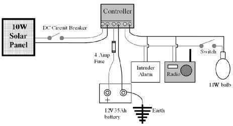
Above: A simple solar installation: a light with light switch, a small radio and a simple intruder alarm - perfect for a garden shed or a small lock-up garage. Because it is a small system, you may choose not to fit an isolation switch. Because the system is very small, I have decided only to fit a fuse between the controller and the battery

This is an interesting project - a solar powered river boat. Electric boats are gaining in popularity, thanks to their virtually silent running and lack of vibration. The only downside is recharging the batteries. Here, solar panels are used to recharge the batteries, charging them up during the week to provide all the power required for a weekend messing about on the river. The total cost of this complete system was less than the cost of a traditional outboard engine and fuel tank
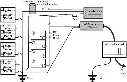
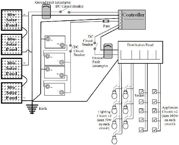
Above: An example of a 12-volt solar system running an AC inverter to provide a normal building electricity supply in an off-grid installation. Below: the same system, wired at 24 volts

The holiday home wiring diagram
The next step
Once you have your wiring diagram, it is time to start adding cables, battery terminal clamps, fuses, isolation switches, earthing rods (referred to as grounding rods in North America) and, in this case, a distribution panel (otherwise known as a consumer unit) to your shopping list. It can help to add more detail to your wiring diagram as well, noting the locations of appliances and sockets, and the lengths of cables at each point.
Solar frame mounting
There are off-the-shelf solar array frames available, and your solar panel supplier will be able to advise you on your best solution.
Sometimes, however, these are not suitable for your project. In this case, you will either have to fabricate something yourself (angle iron is a useful material for this job) or get a bespoke mounting made specifically for you.
Solar panels in themselves are not heavy, but you do need to take into account the effect of wind loadings on your mounting structure. If the wind can blow underneath the solar array it will generate a ‘lift’, attempting to pull the array up off the framework. However, a gap beneath the solar array is useful to ensure the array itself does not get too hot. This is especially important in warm climates, where the efficiency of the solar panels themselves drops as they get hotter.
Making sure the mounting is strong enough is especially important as the solar array itself is normally mounted at an optimal angle to capture the noonday sun. This often means that, even if you are installing your solar array onto an existing roof, you may want to install the solar panels at a slightly different angle to the roof itself in order to get the best performance out of your system.
It is therefore imperative that your solar array mounting frame is strong enough to survive 20 years plus in a harsh environment and can be securely mounted.
If you are mounting your solar array on a roof, you must be certain that your roof is strong enough to take this. If you are not certain about this, ask a builder, structural surveyor or architect to assess your roof.
If you are planning to mount your solar array on a pole or on a ground-mounted frame, you will need to make plans for some good strong foundations. Hammering some tent pegs into the ground to hold a ground-mounted frame will not last five minutes in a strong wind, and a pole will quickly blow down if you only use a bucket of cement to hold it in place.
You should build a good foundation consisting of a strong concrete base on a compacted hardcore sub-base to hold a ground-mounted frame, and the frame itself should be anchored using suitable ground anchors, bolted using 25cm-30cm (10"-12") bolts.
For a pole, follow the advice given by the manufacturers. Typically, they need to be set in a concrete foundation that is at least 3 feet (1m) deep, and quite often significantly more.
To mount your solar panels onto your frame, make sure you use high-tensile bolts and self-locking nuts to prevent loosening due to wind vibration.
If your solar array is going to be easily accessible, you may wish to consider an adjustable solar mounting system so you can adjust the angle of tilt throughout the year. You can then increase the tilt during the winter in order to capture more winter sun, and decrease the tilt during the spring and summer in order to improve performance during those seasons.
For the holiday home project, the solar array is to be fitted to a specially constructed garden store with an angled roof. The benefit of this approach is that we can build the store at the optimum position to capture the sun. We can also install the batteries and solar controller very close to the solar array. In other words, we are creating an ‘all in one’ power station.
There are a number of regional shed and garden building manufacturers who will build a garden store like this to your specification. A good quality store, so long as it is treated every 2-3 years, will easily last 25-30 years.
If you go this route, make sure your chosen manufacturer knows what you are planning to use it for. You need to specify the following things:
· The angle of the roof has to be accurate in order to have the solar panels in their optimum position
· The roof itself has to be reinforced to be able to take the additional weight of the solar array
· The floor of the garden store (where the batteries are stored) must be made of wood. Batteries do not work well on a concrete base in winter
· There must be ventilation built into the store in order to allow the hydrogen gas generated by the batteries to disperse safely through the top of the roof
· The door to the garden store itself should be large enough for you to easily install, check and maintain the batteries
· You should consider insulating the floor, walls and ceiling in the garden store, either using polystyrene (Styrofoam) sheets or loft insulation. This will help keep the batteries from getting too cold in winter or too hot in summer
A garden store will still require a solid concrete foundation. Consideration of rainwater runoff is also important, to ensure the garden store does not end up standing in a pool of water.
Positioning batteries
You will have already identified a suitable location for your batteries. As discussed on the chapter on site surveys, your location needs to fit the following criteria:
· Water- and weather-proof
· Not affected by direct sunlight
· Insulated to protect against extremes of temperature
· Facilities to ventilate gases
· Protected from sources of ignition
· Away from children and pets
Lead acid batteries give off very small quantities of explosive hydrogen gas when charging. You must ensure that, wherever your batteries are stored, the area receives adequate external ventilation so that these gases cannot build up.
Because of the extremely high potential currents involved with lead acid batteries, the batteries must be in a secure area away from children and pets.
Do not install batteries directly onto a concrete floor. In extremely cold weather, concrete can cause an additional temperature drop inside the batteries that will adversely affect performance.
You need to ensure that your batteries are accessible for regular checks and maintenance. Many deep-cycle batteries require watering several times each year and connections must be checked regularly to ensure they have not corroded.
For all of the above reasons, batteries are often mounted on heavy-duty racking, which is then made secure using an open-mesh cage.
If you are installing your batteries in an area that can get very cold or very hot, you should also insulate your batteries. Extreme temperatures adversely affect the performance of batteries, so if your batteries are likely to be in an area where the temperature drops below 8°C (46°F) or rise above 40°C (104°F), you should consider providing insulation. If the temperature is likely to drop below freezing, you must provide it.
You can use polystyrene (Styrofoam) sheets underneath and around the sides of the batteries to keep them insulated. Alternatively, foil-backed bubble-wrap insulation (available from any DIY store in the insulation section) is even easier to use and has the benefit that it does not disintegrate if you ever get battery acid splashed on it.
Never insulate the top of the batteries, as this will stop them from venting properly and may cause shorts in the batteries if the insulating material you use is conductive.
Planning the installation
By now, you should have a complete shopping list for all the components you need. You should know where everything is to be positioned and what you need to in order to proceed.
Before placing any equipment orders, go back to your site and check everything one last time. Make sure that where you planned to site your array, controller, batteries and so on is still suitable and that you have not overlooked anything.
Once you are entirely satisfied that everything is right, place your orders for your equipment.
Bear in mind that some specialist equipment is often only built to order and may not be available straight away. If you require bespoke items such as solar mounting frames, or, as in the case of the holiday home, a complete garden store made up for mounting the solar panels and holding the batteries and controller, take into account that this could take a few weeks to be built for you.
In conclusion
· The detailed design ensures you have not overlooked any area of the design
· Consider the safety aspects of your system in your design. At each stage, ask yourself “What is the worst that can happen?” and then design around the problems
· The wiring diagram helps you envisage how the installation will work
· You need to keep cable runs as short as practically possible. You can do this by running several cables in parallel, either directly from the controller, through a junction box or through a distribution panel
· Splitting the cables into parallel circuits also means you reduce the current load on each circuit, thereby reducing resistance and improving the efficiency of your system
· If you are using an inverter to run at grid-level voltages, a qualified electrician is required to handle the electrical installation. However, your wiring diagram will help your electrician to envisage how your solar electric system should work
· You need to design your battery storage area to ensure your batteries can perform to the best of their ability