Workshop Mastery with Jimmy DiResta: A Guide to Working with Metal, Wood, Plastic, and Leather - Jimmy DiResta, John Baichtal (2016)
Chapter 7. Building Your Own Tools
I love using tools, but also making them, restoring old ones, and modifying them to work better. There are so many tools in my workshop that I have made better in some way. In some cases I’ll take an unwanted old tool and make it completely different, like the machete project from Chapter 2. In other cases, I combine two tools into one, like the Which Blade 1 seen in Figure 7-1.
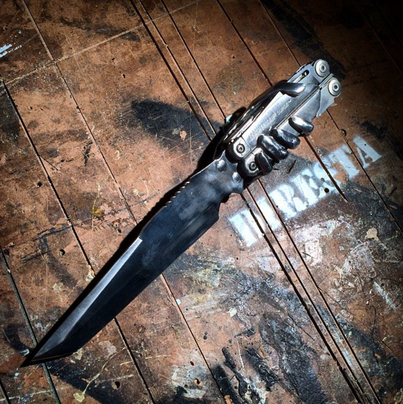
Figure 7-1. The Which Blade 1 mashes up a fixed-blade knife and a multitool
In this chapter I’ll share some of my favorite modified tools, and then will guide you step by step through five fun projects: creating an aluminum handle for an axe, making a locket with three keys attached to it, constructing a brass-ringed wooden mallet, making a wavy-bladed kris knife, and cranking out a production run of a hundred ice picks.
Gallery of Modified Tools
The following are some of my favorite created or modified tools.
Buck Auto-Knife
I converted a classic Buck knife (seen in Figure 7-2) into an auto-knife—a “switchblade”—by adding a length of steel harvested from an old spring, along with a button to keep it in place. I made a couple of mistakes in the build that resulted in the knife being ruined, but I plan on revamping my design and making another go of it.
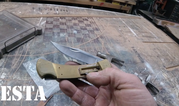
Figure 7-2. This project adds a button and a stronger spring to a regular Buck knife
Bottle Openers
One of my videos features 12 bottle openers repurposed from other tools: a putty knife, an old wrench, and so on. One of the variants was a chisel equipped with a cap-lifting tongue (seen in Figure 7-3) thanks to my drill press. Another consisted of a long screwdriver whose driving end was twisted into a bottle-lifter.
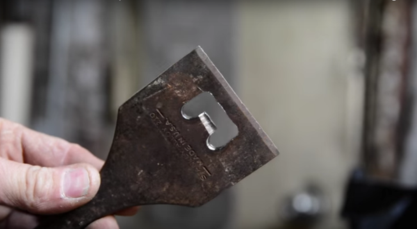
Figure 7-3. I made a dozen bottle openers using different repurposed tools
Chisel Makeover
I restored an old chisel (Figure 7-4) by patching up its broken end using my welder, sanding down the rough edges with my Beaumont belt sender, then sharpening the chisel on my Veritas Mk. II knife sharpener. I finished off the project with a lovely brass handle I turned on my lathe.
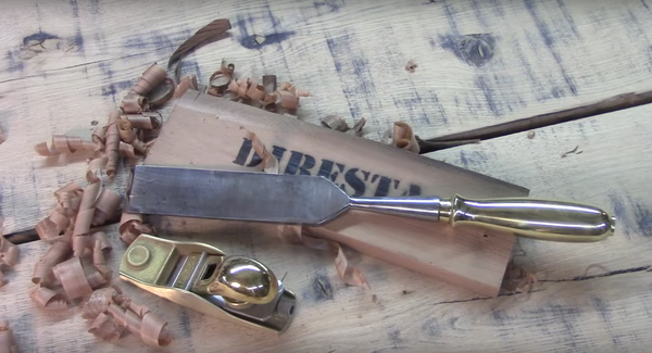
Figure 7-4. I restored this old chisel and added a brass handle
Dagger from File
This is another project involving converting one tool to another. I was inspired by a trip to the Pittsburgh Maker Faire, where I met an artist making his own knives, including ones ground out of old files. I had an old file and I decided that I wanted to turn it into a medieval-style dagger.
First I heated the file in my forge to remove the temper, then ground a point onto the end of it. Next I beveled the blade using my Bridgeport vertical mill, then smoothed down the bevels on the belt sander. I made the bottom part of the file into the hilt of the dagger, giving it a nice knurled grip. I originally intended to wrap the handle in leather, but I liked the old file pattern so much I kept it.
I re-tempered the blade in my forge and quenched it in oil, then made a black leather sheath that matched the dark steel. You can see the finished dagger in Figure 7-5.
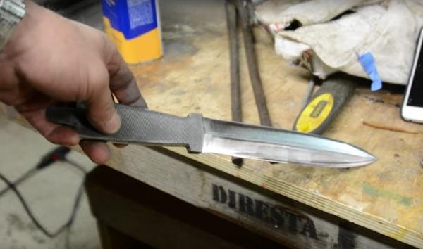
Figure 7-5. I ground a dagger out of an old file
Estwing Hatchet
Estwing makes some lovely hatchets, and their distinctive leather handles make them stand out from the competition. However, that organic handle is always the first part of the hatchet to deteriorate. I took an old Estwing with a corroded head and rotten handle and refurbished it, cutting off the old leather and replacing it with a polished padauk-wood handle. I even braided my own leather lanyard. You can see the finished hatchet in Figure 7-6.
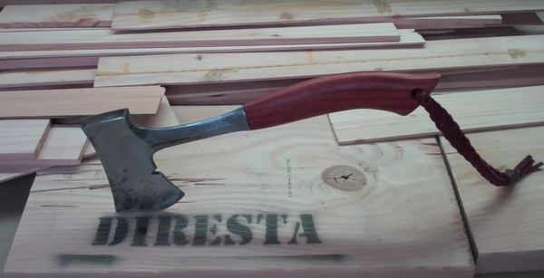
Figure 7-6. This Estwing hatchet has a new padauk-wood handle
Fireman’s Axe
Another axe project! I restored a classic True Temper Kelly Standard pick-head axe that was missing its handle. I restored the head first, sandblasting off the corrosion and then polishing up the metal with my grinder and palm sander.
To shape the point where the handle goes into the head, I filled it with Mold Max castable rubber, giving me a very accurate sense of the shape I needed to make the ash handle. The head, meanwhile, was sent out to Performance Plating in Kansas City to be covered in chrome. Finally, and like a lot of my bladed projects, I took the time to build a black leather sheath, seen in Figure 7-7. Thanks to Tracy for donating the axe head and handle blank!
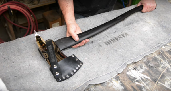
Figure 7-7. This fireman’s axe sports a chrome-plated head and blackened ash handle
Hammer Hook and Loop
I needed a hammer for use up on a ladder. Some pants come with a hammer loop, but you can’t count on that! I welded a hook right on the handle of an Estwing hammer, positioning the hardware in such a way that it would be ready for use when I grabbed it. I also added a loop where I could tie a cord around the hammer, so I wouldn’t drop it off the ladder. You can see the hammer in Figure 7-8.
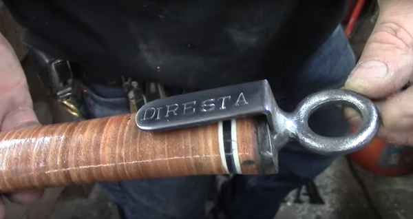
Figure 7-8. Adding a hook and loop onto the end of a regular hammer
Kitchen Knife
I made my own kitchen knife, seen in Figure 7-9. I bought a piece of O-1 oil-hardening tooling steel, ground it into a knife shape, then beveled the cutting edge by clamping it to a plank with a 5% angle and then sliding the assembly past my belt sander. The extra-long handle is made out of Madagascar ebony.
I use this knife all the time in the kitchen, and it’s starting to get a little stained, but it’s still sharp. I plan on making a whole set of kitchen knives.
Figure 7-9. I ground a kitchen knife out of a piece of tooling steel
Leatherman Clip
I love my Leatherman tool; I hate the belt case that came with it. My solution was to TIG-weld a 3/16” stainless steel loop (seen in Figure 7-10) so I could hang it from my belt. The loop attaches to both handles of the multitool, which ordinarily would prevent it from opening up. My solution was to split the loop in two.
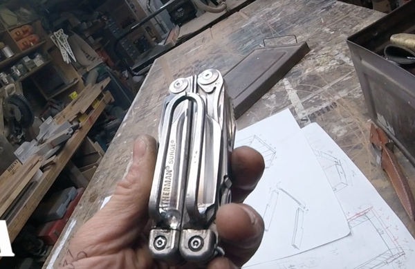
Figure 7-10. Forget belt sheaths; I welded a clip onto mine
Steel Sawhorses
I just got a new welder and needed a project to test it out, so I decided to build a set of steel sawhorses.
I cut eight identical lengths of steel stock, then used my band saw to cut identical notches in the end to ensure they’re angled right. Those notches connected to more lengths of square stock, forming four identical frames of metal. I joined them together with heavy-duty hinges. I ended up with some way-strong sawhorses (seen in Figure 7-11) that are likely to be tougher than any use I’ll come up with.
One of my YouTube commenters said he built a pair of similar steel sawhorses that together held almost 45,000 pounds before they bent. They may not be the strongest in the world, but they’re definitely stronger than the wood sawhorses I own.
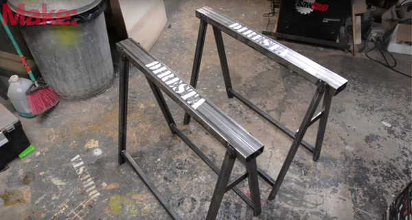
Figure 7-11. Welded steel sawhorses ready for my toughest job
Two-Claw Hammer
For this project, I took an ordinary Estwing claw hammer and welded a crowbar claw onto it, oriented 90 degrees off the other one. I essentially took a crowbar and cut it in half, and added a claw-hammer head. You can see what I came up with in Figure 7-12.
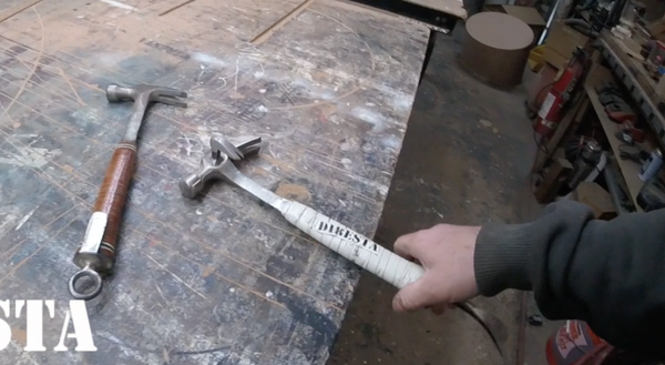
Figure 7-12. I mashed up a crowbar and a claw hammer
The Which Blade
I already mentioned the Which Blade. So there are two variants of a simple idea: using a Leatherman multitool as the handle for another knife. The first blade consisted of a skeleton hand fused to a knife blade, with the hand serving as a holder for the Leatherman. The second Which Blade, seen in Figure 7-13, has a removable fixed blade and uses the Leatherman itself as the handle.
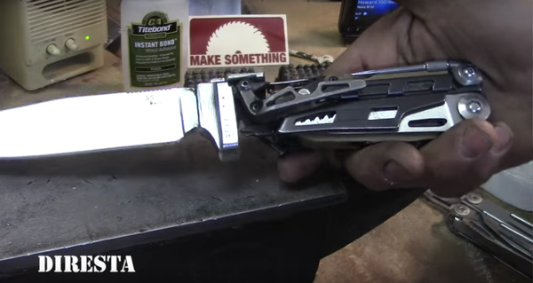
Figure 7-13. The Which Blade 2 features a fixed blade with a multitool handle
Summary
Those were some overviews of modified tools. Now let’s delve into five other builds, and I’ll show you how I created each one.
Bringing an Old Axe Back to Life
I got this double-bitted “Lakeside” axe at a garage sale for 10 bucks, and it’s been hanging in my garage in upstate New York ever since. The axe head is old and rusty, with a broken handle sticking out of it. I always intended to remake the handle, and kept the old stump around so I’d have a really nice pattern for the inside of the head.
After I finished restoring the axe (Figure 7-14) I built a cigar-box-like case for the head out of wood and leather, and it even has a small file stored in the case if I need to sharpen the blade.
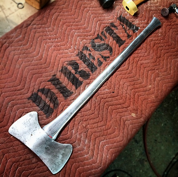
Figure 7-14. This axe needed a new handle, so I created one out of a block of aluminum
Tools and Materials
I used the following power tools in my project:
§ Band saw
§ Beaumont belt sander
§ Buffer
§ Die grinder
§ Dremel with Roto-Zip bit
§ Drill press
§ Palm sander
§ Benchtop sandblaster
§ Table saw
I also used the following hand tools and materials:
§ Angle finder
§ Brass hammer
§ Ball peen hammer
§ Digital caliper
§ Files (flat, bastard)
§ Permanent marker
§ Quick Cure five-minute epoxy
§ PVA bookbinder’s glue
§ West System epoxy
§ West System filleting blend #405
Restoring the Axe
The essence of this project is to cut a plausible axe handle out of a block of aluminum, then smooth it down with saws, files, sanders, and other polishing and cutting devices until it’s just as smooth and comfortable as a “real” handle. This is what I did to build mine:
1. Clean up the head
It’s difficult to work with a dirty tool, so as a first step, I burnished off all the rust and dirt using my benchtop sandblaster. It leaves a dull finish that is a perfect starting point for a restoration and, as the project progressed, I eventually gave it a very nice sheen.
2. Remove the handle
Next I removed what’s left of the handle, while damaging it as little as possible. The handle stump is secured to the head with a steel wedge that splits the handle in half and forces it to press up against the axe head. I used a Dremel rotary tool with a Roto-Zip bit to dig into the wood around the wedge, though it turned out to be very old and dry, and the wedge came out rather quickly.
As soon as the wedge came out, the handle stump pretty much came right off, revealing the exact shape I need to replicate in my aluminum handle. It was interesting seeing the original tooling marks on the handle (Figure 7-15) from when the axe was new, however many years ago!
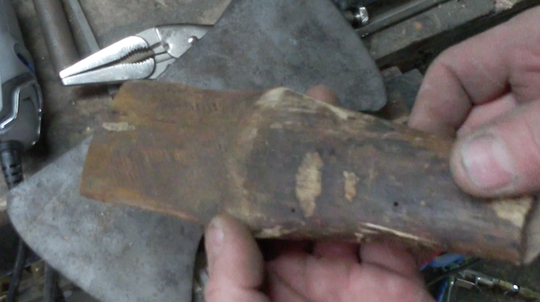
Figure 7-15. The handle’s stump gave me a perfect model for the new handle
3. Design the new handle
I found a piece of general-purpose 6160 aluminum that would form the new handle. It was much heavier than I expected, even though I ended up cutting away 30-40% of the material. First I traced the profile of the old handle (Figure 7-16). Then I drew out the axe handle on the aluminum using a permanent marker. Everyone was impressed that I draw the handle freehand, but I just used the edge of the metal as a guide, holding my fingers to keep the pen steady.
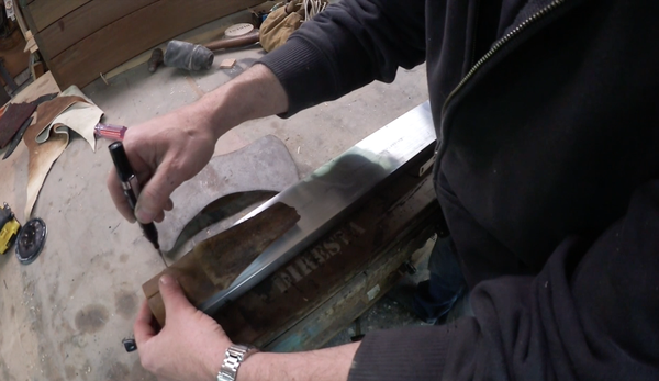
Figure 7-16. Using a permanent marker to draw the shape of the handle on the aluminum
4. Cut the aluminum
I cut out the design on my band saw using a 4 tooth-per-inch (TPI) blade, as seen in Figure 7-17. The metal tends to get gummy, and if you use a typical metal-cutting blade (say, 14 TPI) the metal shavings don’t fall out of the blade and it gets gummed up.
I cut out the left and right sides, then flipped the metal 90 degrees and cut down the sides as well, to give it the beginnings of sort of a taper. I’m basically scalloping out all four sides.
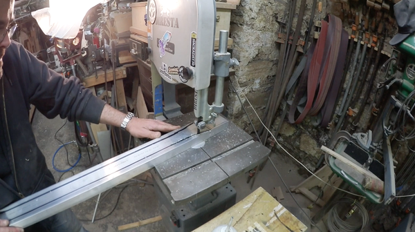
Figure 7-17. Cutting out the design from a block of aluminum
After that I worked on the shoulder, the part of the handle that fits into the axe head. This presented something of a challenge, as I had to drop the shape on the end of the handle and you cut on a band saw by pushing the material into the blade. This means I couldn’t see the line, so I set up my camera to shoot the video and followed along with the lines on the camera’s viewfinder. I angled the material as I shoved it through the saw blade to give it a beveled edge roughly analogous to the socket of the axe head.
After I shaped the shoulder, I beveled the edges of the main handle (Figure 7-18), trying to keep my hands steady so there wouldn’t be any unevenness. I just kept cutting down corners, working off all those facets until I started having a round shape that would fit well in my hand. This technique isn’t perfect, but it’s a lot easier using the saw than working it by hand. Don’t work too quickly—just take little bits out at a time.
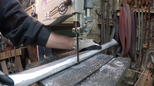
Figure 7-18. I continued to bevel the edges with the band saw
5. Smooth the handle
Once the facets had been cut off as much as possible, the hard work began. I worked over the handle with the lead file some more and used the flexible part of my Beaumont belt sander to help round the edges. I used a pretty aggressive belt on the Beaumont, 80-50—any less and the grit gets gummy.
Next, I worked the handle over with a bastard file. It’s got flat and curved sides, and you’ll need both when making this kind of handle. I found I could really see the blade marks on the handle. Just when I thought I had them all off, I found more. I ended up using a really aggressive rasp because I wasn’t getting enough material off.
I repeatedly measured the widths with my digital caliper to ensure that the final shape would be even. Then I worked over the handle with the Belmont sander (Figure 7-19), my air-powered die grinder, as well as a palm sander. Just work your way down the grits, and you can pretty much get anything shiny.
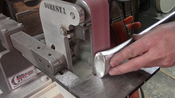
Figure 7-19. I switched to the Belmont sander
6. Add the head
The first step to adding the head is to cut a slot into the shoulder, giving the hand end a degree of flexibility. You’ll eventually add a brass wedge, which will ensure the axe head doesn’t fall off.
At this time I polished up the head (Figure 7-20), but I didn’t overdo it. I liked the wear on the steel from decades of use, and anyway I knew the handle would be shiny, so I left the axe head a little more rough and worn.
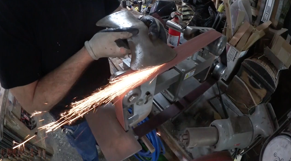
Figure 7-20. Polishing up the axe head just before adding it to the handle
I tapped on the end of the axe handle, inserting the handle into the opening incrementally with every tap. I left enough material sticking out of the top of the head to sand off once the wedge is placed.
7. Add the wedge
When the head was firmly attached, I cut out a piece of brass and shaped it into a wedge on the belt sander. I inserted the wedge and pounded it as far as it would go, then sanded off the excess. Finally, I pounded on the end with a ball peen hammer, just to give it some texture. The axe is done!
8. Build the case edges
Every sharp tool needs a sheath or protective case, and my axe was no different. I cut some walnut panels with finger-jointed ends, and came up with the idea of a case resembling a cigar box to enclose the axe’s head.
Once I had formed the shape I wanted, I added Quick Cure epoxy to the dovetails, then arranged the pieces by hand, as seen in Figure 7-21. I sanded the edges smooth once the epoxy had set, and filled in the excess holes in the dovetail arrangement with West System filleting blend, wood-toned filler that mixes with epoxy.
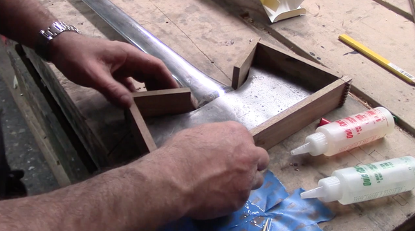
Figure 7-21. I epoxied the dovetailed segments and arranged them by hand
9. Add leather
I had some heavy-duty cowhide from a previous project, and I traced out the head’s shape onto the leather (Figure 7-22), then cut it out roughly with my box cutter. I glued the leather onto the frame with PVA, then trimmed carefully around the edge with an X-Acto knife.
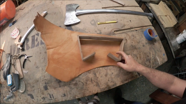
Figure 7-22. Tracing out the shape of the case
10. Finish the case
I cut the case in half. I set up my table saw for the width I wanted (halfway through the case) and rotated the case over the saw blade, eventually cutting it in half. I was very careful to go slow so the blade didn’t grab the case. I made a bunch of passes, rotating the box frequently.
Once I cut the case open, I added small pieces of wood to help keep the axe head from moving around. Next, I secured the leather parts of the case by pre-drilling holes for small brass tacks, then tapped them in with a finishing hammer. After that I added hinges and locking mechanisms, screwing them in place. I didn’t have mirrored locks, so I rotated one 180 degrees, making one lock opposite the other, meaning the case doesn’t really have a top or bottom. Figure 7-23 shows the final case.
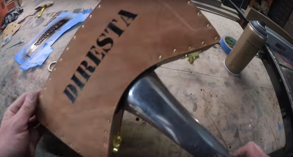
Figure 7-23. Adding a file so the axe can be sharpened in the field
11. Sharpen and use
I sharpened the axe and brought it up to my property in upstate New York, and put it to work by cutting down a dead tree. People ask how comfortable it is to use. It cuts as smooth as you’d like, but it’s heavy!
Summary
This project demonstrates that even an old and rusty axe with a broken handle can be made useful again. All it takes is a lot of hard work and, in the case of this project, a big piece of aluminum!
Making a Star Key Locket
About 20 years ago I decided the sound of jangling keys was annoying to me. I decided to come up with a solution that would let me carry several keys without the noise. The first thing I tried was to put a screw through the holes in the keys, and then simply fanning them out when I needed to unlock something. One day I was fanning them out and realized they looked really cool in a star formation.
To make a star key I soldered the keys to a central hub, almost like a pocket watch (you can see several variations in Figure 7-24). It also got a lot skinnier. Where before it was almost like a pocket knife, a lump in my front pocket, now it’s just a flat key that hangs from my belt or goes into my billfold. Every time I move into a new space I end up creating a new key. Sometimes they’re simpler, like a brass lanyard with a single key soldered to it, but sometimes they’re more complicated.
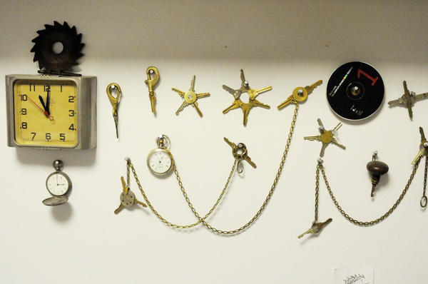
Figure 7-24. Star keys are just the ticket if you don’t like jangling in your pocket
A friend wanted a star key made into a locket, and gave me a vintage button to use. It’s a big brass button that I was going to turn into a locket, with the keys soldered around the periphery.
Tools and Materials
While small, the key project uses a wide variety of tools and materials:
§ Beaumont belt sander
§ Button
§ Brass rod a little bit wider than the button
§ Caliper
§ Cutting fluid
§ Dremel
§ Drill press
§ Jeweler’s saw
§ Keys
§ Lathe
§ Propane torch
§ Silver solder
§ Ultra Flux
§ Wire brush
Assembling the Locket
Here are the steps I took in creating my star key. The main design involves the antique button (Figure 7-25) that my friend supplied.
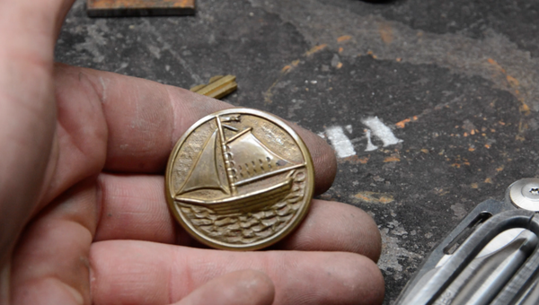
Figure 7-25. This button will serve as the front of the locket
1. Shape the locket backing
The first step is to find a piece of brass that will serve as the back of the locket. Naturally, it’s got to match the diameter of the front. I grabbed a piece of brass rod that a friend saved for me from a recycling plant. A short length of this material will eventually turn into the back of the locket after I run it through the lathe.
I cut off a length of the brass rod and secured it to my lathe. Boring into the end, I cut out a small hollow for the inside of the locket. I used my internal caliper occasionally to make sure I was making the hollow the right size.
2. Clean up the button
Next, I worked on preparing the button. It consisted of a brass cover attached to a backing, with paper batting inside. I used a Dremel and saw bit to cut out the back of the button.
Next, I used an ice pick to clear that paper batting out and then removed the remainder of the backing. I worked really gently because I didn’t want to deform the front of the button, because if it gets deformed it’s garbage.
I tested the button face in the hollowed-out portion of the rod, and when I confirmed it fit, it was time to cut off the locket backing from the rod.
3. Cut off and clean up the backing
I used a lathe’s parting tool (seen in Figure 7-26) to cut into the rod, while simultaneously making an extra groove for the keys to go into.
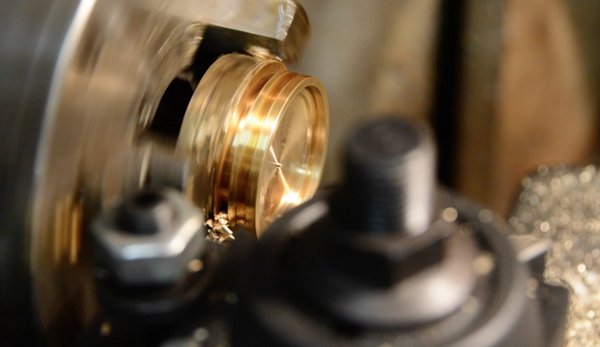
Figure 7-26. Cutting through the brass with a parting tool
I went as deep as I could with the parting tool, then cut off the remainder with a hacksaw. The piece of brass was just too close to the lathe’s three-jaw chuck to cut all the way through with the parting tool.
When the locket backing came off the rod, I cleaned up the back with the sander, dipping it into a cup of water periodically so it wouldn’t get too hot to hold.
4. Build the hardware
I needed to create all-new hardware for the locket—a hinge, as well as a lever to help open it. I used a jeweler’s saw to cut out a small piece of brass for the lever. This will give the user’s finger something to grab ahold of when opening the locket.
I used silver solder to attach the lever to the locket face. First, I threw some flux on the area I wanted to solder, along with some flakes of silver, and then I heated it up with a propane torch. Since the brass button face is so thin, I had a piece of metal underneath, and I directed the torch on this (as seen in Figure 7-27) to avoid overheating the brass. This project was a challenge for me because I’m not used to working tiny!
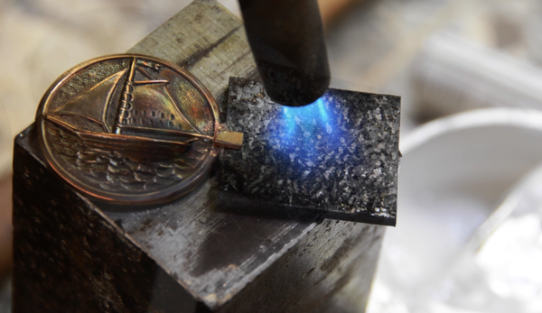
Figure 7-27. Heating up a piece of metal to melt solder
Next, I worked on the hinge. I used my jeweler’s saw to cut out tiny lengths of brass tubing and soldered them onto the locket front and backing. Then I attached the two tubes to the backing, using the hinge pin to keep them aligned.
Unfortunately, while soldering everything into place I soldered the hinge pin, so I had to heat it up red-hot and remove it, as seen in Figure 7-28. For the most part, silver solder is very controllable and it’s easy to pinpoint what you want to get hot and what you don’t.
It also helps to work on steel blocks, positioned to serve as heat sinks for the parts of the locket I don’t want to get hot. Once I had the hinge the way I wanted it, I re-inserted the hinge pin and sanded off the extra portion.
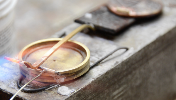
Figure 7-28. Soldering hinge tubes to the locket back. The larger piece of brass holds the tubes in place.
5. Solder in the keys
Then it was time to add the three keys. First, I cut off the backs of the keys. Next, I inserted the first key into that groove in the side of the locket back, then coated the end in flux.
Figure 7-29 shows the first key in place. Notice how I positioned the key so it was cantilevered between two steel blocks, essentially excluding that part of the locket from the heat sink.
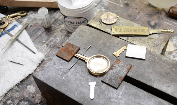
Figure 7-29. Arranging the keys with steel blocks underneath to serve as heat sinks
Then I heated the brass with the torch while applying a length of silver solder. I worked my way around and soldered in all three keys. I covered the hinge with a steel plate to avoid re-activating the solder and knocking those hinge tubes out of position.
After I’d soldered in all three keys, I quenched the locket in a cup of water and cleaned it up with a brass wire brush in a drill press. When it was clean, I stamped my name in the inside.
My friend wanted the star key on a lanyard, so I drilled a hole in one of the keys and added a jump ring. It’s done! Figure 7-30 shows the completed project.
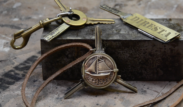
Figure 7-30. The finished star key locket, along with a couple other key projects I worked on
Summary
This project challenged me for a couple of reasons. Not only had I never made a locket before, I had also never used silver solder. A new technique plus a new topic make for a very fun project!
Building a Brass-Ringed Mallet
I got a really great piece of 2”-thick white oak from a sawmill in Woodstock, New York. It had been drying for a long time, but was finally ready to be put to work. I used it to create a mallet with a brass-edged head. You can see the finished project in Figure 7-31.
The mallet isn’t to pound nails or other metal objects. At the same time, it’s also not for pounding wood, as the brass rings that reinforce the mallet head could ding the material. I’m mostly going to use it for mortising and for hitting the backs of chisels.
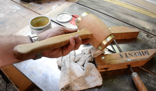
Figure 7-31. I made this mallet out of white oak and brass
Tools and Materials
I used the following tools and materials to make my mallet:
§ Band saw
§ Briwax clear wood polish
§ Caliper
§ Chop saw
§ Planer
§ Lathe
§ Scotch-Brite pad
§ Screw clamps
§ Shoulder plane
§ Table saw
§ Titebond glue
§ White oak
Building the Mallet
To create my mallet I followed these steps:
1. Cut off the handle portion
The first thing I did was cut a 1” strip off of one side of the board. This will be the mallet’s handle, and ultimately I’m going to round it in the lathe to make it grip easier. For now, however, I’m going to set it aside and work on the head portion for awhile.
2. Smooth the wood
The white oak’s surface still had band saw marks on it that I needed to remove, so I ran the remainder of the board through the planer. I wanted the wood as smooth as possible, because I would be gluing it together.
3. Cut up the board
There was a twist in the wood, so I played it safe and cut it halfway through—I was afraid the wood would bind if I made a full-depth cut, so I only cut halfway through, flipped over the board, then cut the rest of the way. I cut off two short sections on the chop saw to serve as the head.
4. Shape the handle
I grabbed the 1” piece of wood I’d cut off the edge of the board. This will be the mallet’s handle. I drew the shape of the handle on the wood, working from memory to re-create a mallet handle I’d used in the past. It won’t be glued, nailed, or anything else—it holds onto the head through a tapering of the wood, seen in Figure 7-32. Having drawn the shape of the handle on the strip of wood, I cut it out using my band saw.
Figure 7-32. Cutting out the handle
5. Cut and glue the head
I wanted to ensure that the handle fit snugly, so once I finalized its shape, I worked on the socket in the mallet’s head. I drew a rectangle (seen in Figure 7-33) on the twin pieces of wood that make up the mallet head.
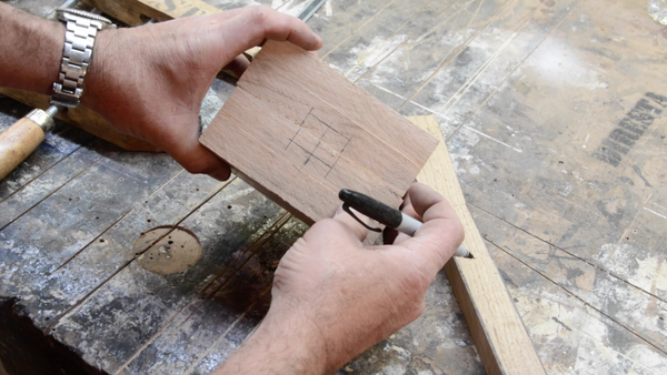
Figure 7-33. Drawing the hole for the mallet handle
I cut out the shape using the table saw, making multiple small cuts with the help of the saw’s sled in order to make a precise hole for the handle.
Once the channel was cut, I needed to modify it to make it match the taper of the handle. I drew cut lines on the wood, then brought it back to the table saw.
I re-cut the hole, but this time at an angle to capture the negative of the handle’s wedge shape. I used a chunk of wood to angle the blocks of white oak so that the blade’s cut matches the taper I’d drawn on the wood.
It was a somewhat painstaking process because the angles have to be even or the handle won’t fit or will be angled oddly. I used the cut line on the sled as a guide for getting the angle right. After I’d cut one channel, I made a test fit and then cut the other one.
I used a shoulder plane to smooth out the inside of the groove, then glued the head together using Titebond wood glue (Figure 7-34) and clamped it.
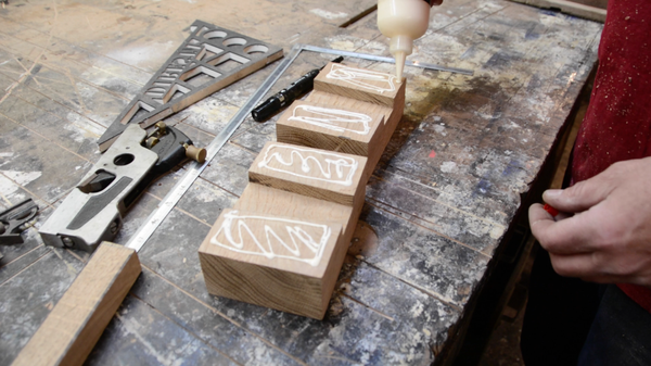
Figure 7-34. Gluing the halves of the mallet head
6. Shape the handle on the lathe
While the head’s glue was drying, I put the handle in the lathe and went to work with a chisel. I wasn’t trying to make a perfectly circular handle; I just wanted to round the edges. After I had shaped it the way I wanted it, I sanded it and did a test fit with the now-dried head.
7. Shape the head
I found the center of the end and used a compass to make a circle. It’s possible to use the lathe to make a block into a circle, but I find cutting off the corners saves a lot of time.
Next, I set my band saw for 45 degrees and roughed out the corners, making my job with the lathe easier—smoothing out a cube of wood is a lot of work, and really noisy as well!
Then I put the head in the lathe (Figure 7-35) and worked on it with the chisel. It’s very deceiving because it looks perfect when the lathe is spinning! Of course, you get a more accurate picture once the lathe has stopped, so I kept checking it.
One area that concerned me was that the hole in the head was chipping out when the chisel hit it, so I added some crazy glue around the edges to reinforce it. The glue keeps the fibers in place.
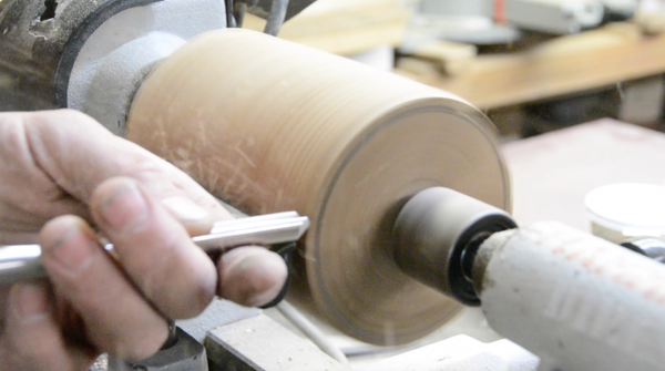
Figure 7-35. Smoothing the mallet head on the lathe
When I started getting the head where I wanted it, I cut into the ends, because ultimately I want to attach brass rings to the ends to reinforce them. The outer diameter of the brass pipe I’m using is three inches, so I kept the wood a hair over; I could always take it in if it was too wide. I played it safe and took a little bit off, then checked with my caliper to ensure I wasn’t going too far.
I gave the head almost a football shape, tapered in at the ends. It’s mostly for aesthetics, but it also accommodates the fact that my brass rings are three inches in diameter. Figure 7-36 shows the hammer’s shape. Finally, I sanded the head with the pad from a disc sander while it spun on the lathe.
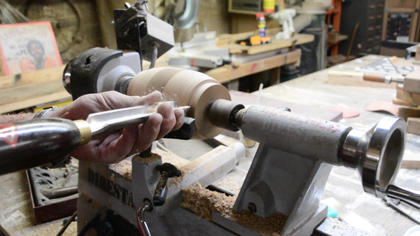
Figure 7-36. The head takes on a “football” shape
8. Add the brass rings
With the wood portion of the project done, I worked on the brass rings. I cut off 1” sections of brass pipe using my portable band saw.
Next, I cleaned up the rings in the belt sander. I hadn’t made the effort to ensure the cuts I made were straight, so I held the brass rings firmly against the table of the saw so they would sand evenly.
When I milled the ends of the hammer, I tapered them somewhat so the rings would go on readily at first, but would need to be pounded into place to make them fully flush. While I was at it, I made a chamfer (a sloping surface) on each ring to help it fit onto the head.
I inserted the handle, which stays on with friction only. Holding the mallet by the handle, I tapped the rings into place. You can see me at work in Figure 7-37. I went slow, not wanting to damage the brass or oak.
When I had the rings pounded in as much as they would go, I brought the mallet to the belt sander and polished off the ends of the brass rings. While I was at it, I rounded the end of the handle sticking out.
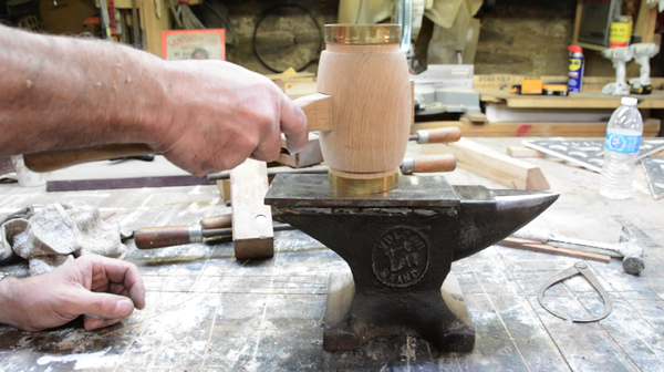
Figure 7-37. Tapping the brass into place
9. Finish the mallet
I used a Scotch-Brite on the rings and Briwax to seal the wood. The mallet is done! I’m really proud of how it turned out.
Summary
One of the best reasons to make a tool is so you have it to use in the future. I can’t wait to use my mallet in a future project. Now, build yourself one!
Mass-Producing a Signature Ice Pick
An ice pick is simply one of the tools I carry on my person. It’s good for touching or moving something hot or sticky, things you don’t want to touch with your hand. The project consists of a commercial ice pick with a replacement brass handle and protective sheath that lets you keep it in your pocket. You can see several of the picks in Figure 7-38.
For a long time I encouraged people to make their own, and people suggested I presell a batch of ice picks. I did, and sold over 100 of them, and that encouraged me to make more batches. Right now I’m sitting at over 1,000 ice picks manufactured. Follow along to see how I made them.
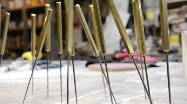
Figure 7-38. I didn’t just make an ice pick, I made hundreds of them
Tools and Materials
The parts list for this project included the following:
§ Band saw
§ Box cutter
§ Brass stock: hexagonal and tubular
§ Brass ring
§ Cyanoacrelate (a.k.a. “crazy”) glue
§ Lathe
§ Propane torch
§ Shopbot CNC router with a V bit
§ Silver solder
§ 3-in-One cutting oil
§ Ultra Flux
§ Vise
Building the Ice Picks
The actual process of creating the ice picks is relatively brief, but it seems much longer when you consider I built over 100 of them in the following steps:
1. Remove handle from ice pick
I began by placing each ice pick in the jaws of my vise and yanking off the wooden handle. I dumped the handles and kept the picks.
2. Cut the hexagonal stock
I cut the handles out of 3/8” hexagonal brass stock, purchased from onlinemetals.com. Figure 7-39 shows me cutting the stock on the band saw.
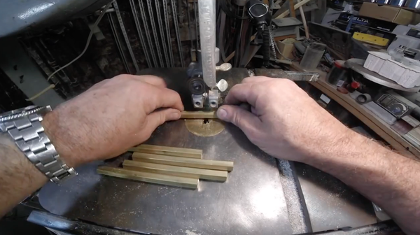
Figure 7-39. Cutting handles out of brass stock
3. Engrave the handle
I set up a jig on my ShopBot CNC router, attached a V bit, and engraved my logo into every one of those handles.
4. Drill the handle
I put each length of hexagonal stock in my 16” lathe and drilled one end with a 1/8” bit. I made sure to use cutting oil because I was going to be making a lot of handles.
5. Taper the ends of the handle
I pencil-pointed both ends of the handle (Figure 7-40) with the lathe’s cutting tool. The tapers will help give the ice pick a finished look.
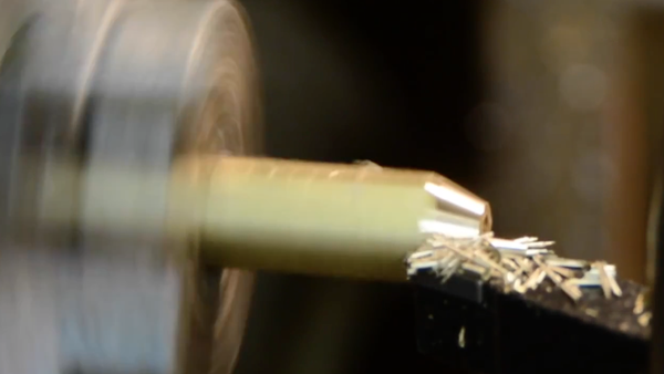
Figure 7-40. I tapered both ends of each handle
6. Cut the brass tubing
The business end of the pick is protected with a brass “sheath” consisting of a length of tubing. I cut a bunch of lengths of tubing on the band saw.
7. Cut notches in the tubes
I used my Grizzly milling machine with a 1/8” mandrel bit to cut precise notches (seen in Figure 7-41) in the sheaths. These notches will accommodate brass rings.
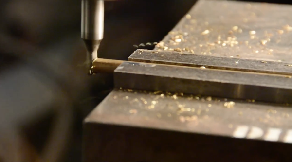
Figure 7-41. Using a mandrel bit to cut a rounded notch in the end of each sheath
8. Solder on a ring
I placed the notched tubing on a special rig I welded together (seen in Figure 7-42) with a brass ring crimped into the notch. Then I dabbed some Ultra Flux and set a piece of silver solder on the join. When it was ready, I melted the solder with a pair of propane torches, and the melted silver fell into the crack. For future production runs I did away with the metal rig because it soaked up too much heat.
The final step to the soldering process involves quenching the join in a solution that clears away the excess flux before it adheres to the surface.
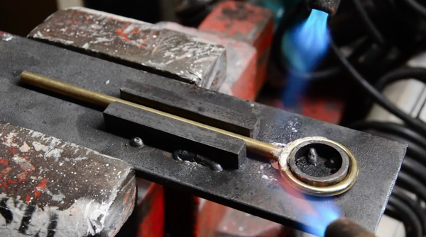
Figure 7-42. Soldering on the rings
9. Glue in the picks
I dipped the non-pointy ends of the picks into CA (cyanoacrelate or “crazy”) glue and inserted them into the handles.People are surprised to see me use CA glue for this purpose. I do this for a very specific reason. If you use the pick, you might break the tip off. Just go buy another ice pick, heat the handle up and remove the broken part, then crazy-glue in the new part. Then I put each pick in my hand drill and polished off any excess glue using a razor blade and Scotch-Brite pad.
10. Add the dimple
I had an idea for securing the sheath to the handle, and it involves a dimple. With a hammer and tap, I made a small dent in the sheath. The dimple creates friction that keeps the sheath in place.
11. Cut the sheaths
First I set up a small saw blade on my lathe, and then I split the ends of the sheaths so that the slot runs perpendicular to the dimple. When I was done I buffed the cut ends smooth.
12. They’re done!
I put the sheaths on the picks (Figure 7-43) and got ready to send them off.
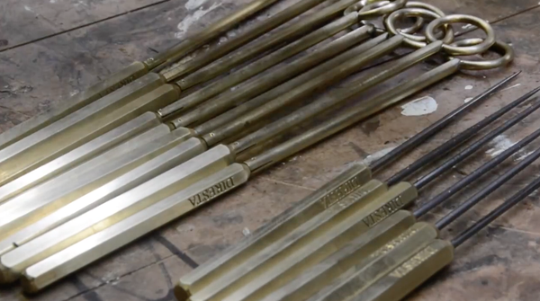
Figure 7-43. The completed ice picks ready to mail
Summary
This project presented a new challenge to me: I wanted to manufacture and sell a product. I’d love for you to build your own version of this project. However, if you’d rather get one of these, I sell them at http://shop.jimmydiresta.com.
Grinding My Own Kris Knife
This knife (seen in Figure 7-44) is really the first one I ever made from scratch. I decided to make the most complicated shape the first time out because it can only get easier from there! I made a wavy-bladed knife, often called a kris- or Indonesian-style blade.
The knife was an ambitious project and I went in thinking it would be easy to complete, but it became one of those projects that started to linger. I kept thinking, “Ugh, I have to go back and work on that knife” and ultimately I set it aside for six months. When I purchased a metalworking forge and was able to heat-treat the steel properly, I picked the project back up and finished it. I’m really proud of how it turned out.
Figure 7-44. I challenged myself by building a complicated design: a kris knife
Tools and Materials
As you might imagine, most of the tools I used in this project involved grinding and polishing the metal:
§ Beaumont sander
§ Table saw
§ Rigid milling machine
§ Band saw
§ Hand files
§ Grinder with a 8” disk
§ Pneumatic die grinder with a Scotch-Brite disk
§ Burbinga wood
§ Brass stock
§ Five-minute epoxy
§ 3/16” × 1.5” piece of steel
§ 3M #77 spray adhesive
Creating the Knife
I followed these steps to make my knife:
1. Apply the design
I sketched out the design a few times before I made one I liked. Then I sprayed down a piece of A-2 steel, 3/16” thick by 1.5” wide, with some 3M #77 spray adhesive and stuck my design to the metal. Figure 7-45 shows me applying the design.
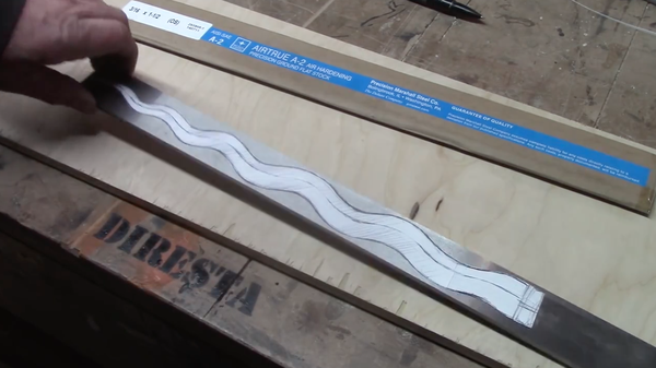
Figure 7-45. Gluing the design to the steel stock
2. Grind out the blade
I tried a couple of different ways to cut out my design, beginning with a band saw and jeweler’s saw. I eventually figured out the easiest way would be to literally grind the excess material away, as seen in Figure 7-46. I have this crazy 8” grinding disk that literally turns the blade’s negative space into dust. It’s incredibly noisy and I’m wearing ear protection, as well as a dust mask and a protective face shield.
As always, I kept the paper design on the steel as long as possible, and as long as I stayed outside the line I was happy.
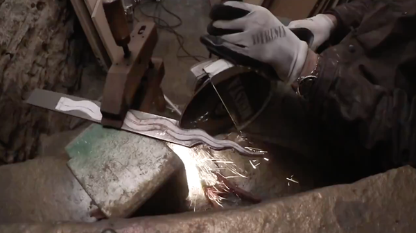
Figure 7-46. Grinding the wavy shape out of a piece of steel
3. Clean up the curves
The next thing I did was to sand down the knife’s curves using my Beaumont belt sander, which was designed for knife making. I wanted the edge to be as smooth and consistent as possible, because if the pattern of curves was off, the eye would spot it immediately.
4. Bevel the blade
I drew a line bisecting the edge of the blade so I could see where the future edge would be. I wanted a double bevel, where the blade narrows evenly from both sides. I also wanted a center line along the flats of the blade, sort of a ridge mirroring the curves of the blade.
Then I went to work using an electric die grinder with a burr attachment. You can see me working in Figure 7-47. That burr is super strong and carves that metal right away. I would periodically draw in Sharpie on the part I wanted to grind, so that I could gauge my progress. After I had finished one side, I flipped it over and redrew the center line, and kept grinding.
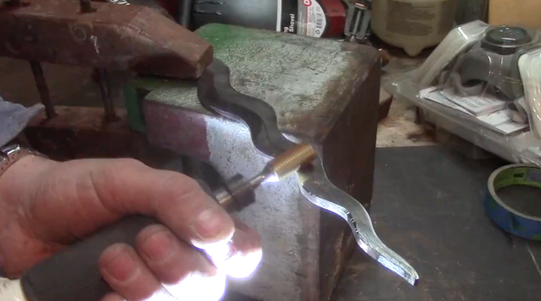
Figure 7-47. Grinding away at the metal
5. File the blade
After I had ground away a bunch of material I brought the knife back to the Beaumont. Unfortunately it wasn’t as much of a help as I thought it would be—I simply wasn’t getting the results I was expecting because it was harder to see what I was grinding. It was easier to work on it with a hand file (Figure 7-48) because I could see what I was doing. It took days and days of work to get the blade shaped the way I wanted it.
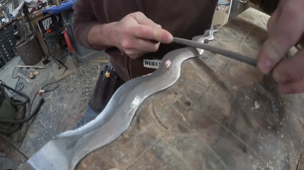
Figure 7-48. Working with hand files to finish the blade
6. Polish the steel
When I was finally done shaping the steel, I polished it up with a pneumatic die grinder and a Scotch-Brite disk.
7. Heat-treat the blade
I heated up the blade in my propane furnace (seen in Figure 7-49) and when it was nice and red-hot, I left it out to cool. The kind of steel I used (A-2) belongs to a category of alloys called air-hardening steel, and part of the tempering process involves heating up the metal to upwards of 1700 degrees F, then letting it air-cool. After it had cooled I put it in my oven at 400 degrees to complete the tempering process.
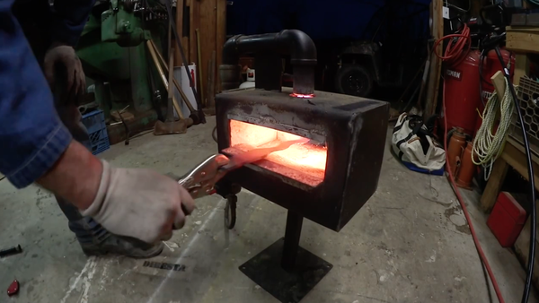
Figure 7-49. Tempering the steel
8. Cut wood for the case
I was originally going to put the blade inside a cane, but during the six months when this project was quiescent, I decided it was just too fat. Instead I made a case that wasn’t shaped like the blade—it would be totally rectangular.
I cut three strips of bubinga wood on my table saw, each big enough to fit the entire blade. The strips will form the case, with the center one cut to accommodate the blade.
9. Glue the case
I used Titebond wood glue, and secured everything with brad nails and a whole bunch of clamps. I attached just two of the three layers at first, then added the final layer once the first two were set.
10. Sharpen the blade
While the case was drying, I went back to the Beaumont and worked on sharpening up the edge. I really wanted to shave with the knife, but unfortunately I just couldn’t get it sharp enough. While I was at it, I polished up the blade again with my die grinder. When I heat-treated the blade, it had been scorched black, and I polished off the soot.
11. Drill the tang
The part of the knife under the handle is called the tang. I drilled four holes in my knife’s tang (Figure 7-50). I’ll epoxy the handle on, and the holes are just there to give the glue something to grab ahold of.
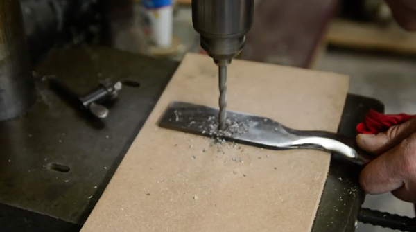
Figure 7-50. I drilled some holes in the knife’s tang to give the glue a little extra gripping power
12. Machine the guard
There is a little piece of metal that caps the handle as it meets the blade, called the guard. I used my Bridgeport mill to grind out the footprint of the blade, then cleaned it up on the Beaumont.
13. Cut apart the case
You’ve probably noticed the hilt and case are all in one piece; this is because I wanted the two parts to fit together relatively seamlessly. However, it was time to cut them apart on the band saw.
14. Epoxy the knife
I mixed up some five-minute epoxy and inserted the tang onto the blade, then slid it down until it was snug against the hilt.
15. Finish
I brought the knife to my Beaumont again and sanded down the edges of the case and hilt, including the part where the brass guard extends over the wood—I wanted them to be flush. I kept it slow so the epoxy wouldn’t heat up and loosen. Finally, I rubbed the case down with boiled linseed oil. Figure 7-51 shows the completed kris knife.
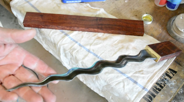
Figure 7-51. My finished knife, looking good!
Summary
Considering how many months it took to make the kris knife, I’m really pleased with how it turned out. Finishing my first ever knife, and one with a difficult design, gave me a lot of confidence for future projects.
You’ve also reached the end of the book! Throughout this book I’ve shared my passion and knowledge of tools and materials, and I hope you find inspiration in these pages. Good luck with your next project!