The Complete Guide to Wiring, Updated 6th Edition: Current with 2014-2017 Electrical Codes - Black & Decker, Cool Springs Press (2014)
Chapter 4. Switches
Among wiring devices, switches fail with surprising frequency. If you’ve carefully wired a new circuit or a fixture and you know you got it right, but when you turn on the power it doesn’t work, you should direct your attention to any switches in the line. Even brand-new switches can fail to function correctly. This is why most professional electricians will pay the extra couple of dollars to buy a quality switch out of the gate. It is also why most of them routinely test each switch for continuity before installing it (see pages 98 to 101).
The most basic switches for home wiring are single-pole switches, which control only one fixture and have only two screw (or push-in) terminals (not counting the grounding screw). Next, three-way switches and four-way switches have more installation possibilities and control circuits that are more complicated to wire. Dimmer switches, isolated ground switches, and motion-sensor switches are some of the other switch options.
Use caution when you handle switches. The wires are usually attached to screw terminals on the sides of the fitting, which makes them very easy to contact if you grab the switch. Always shut off the power to the switch before removing the switch cover plate. Also shut off the power at the service panel if you will be working downline from the switch—never count on a switch that is open to function as a breaker.
In this chapter:
![]() Wall Switches
Wall Switches
![]() Types of Wall Switches
Types of Wall Switches
![]() Specialty Switches
Specialty Switches
![]() Testing Switches
Testing Switches
![]() Wall Switches
Wall Switches
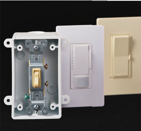
An average wall switch is turned on and off more than 1,000 times each year. Because switches receive constant use, wire connections can loosen and switch parts gradually wear out. If a switch no longer operates smoothly, it must be replaced.
The methods for replacing a switch vary slightly, depending on the switch type and its location along an electrical circuit. When working on a switch, use the photographs on pages 86 to 100 to identify your switch type and its wiring configuration. Individual switch styles may vary from manufacturer to manufacturer, but the basic switch types are universal.
It is possible to replace most ordinary wall switches with a specialty switch, such as a timer switch or an electronic switch. When installing a specialty switch, make sure it is compatible with the wiring configuration and size of the switch box. Notice: Two changes in the NEC affect how new switch wiring should be installed. These changes do not affect existing switch wiring. The pictures and instructions in this book about replacing existing switches show wiring that does not comply with these new requirements. This is because you will probably see non-compliant wiring for many years to come. Pictures and instructions about installing new switch wiring show wiring that complies with these new requirements.
One change requires that a wire with white insulation should not supply current to a light or receptacle, even when the wire is marked as hot. A black or red colored wire should supply current to the device. A white colored wire, marked as hot, may supply current to the switch.
The other change requires that a neutral wire be available at switch boxes. An exception allows you to ignore this requirement if the switch box is accessible from above or below, such as from a basement, crawlspace, or attic. This new requirement is intended to allow easier installation of devices, such as intelligent switch controllers, that need power for controller operation.
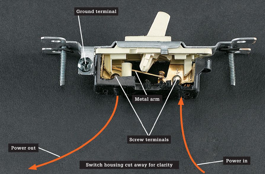
A typical wall switch has a movable metal arm that opens and closes the electrical circuit. When the switch is ON, the arm completes the circuit and power flows between the screw terminals and through the black hot wire to the light fixture. When the switch is OFF, the arm lifts away to interrupt the circuit, and no power flows. Switch problems can occur if the screw terminals are not tight or if the metal arm inside the switch wears out. Note: The switch above has had part of its housing removed so the interior workings can be seen. Switches or fixtures that are not in original condition should never be installed.
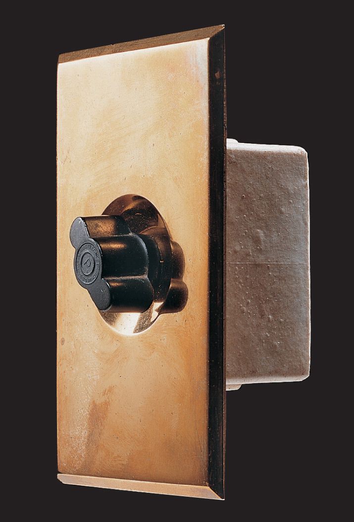
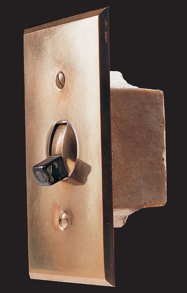
Rotary snap switches are found in many installations completed between 1900 and 1920. The handle is twisted clockwise to turn light on and off. The switch is enclosed in a ceramic housing.
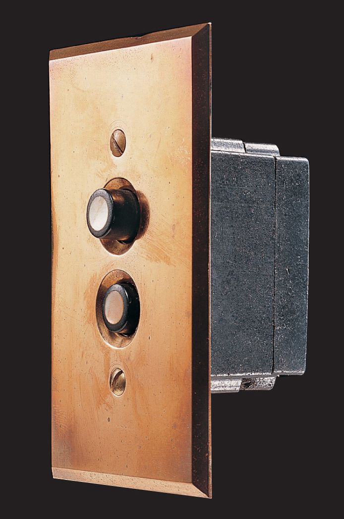
Push-button switches were widely used from 1920 until about 1940. Many switches of this type are still in operation. Reproductions of this switch type are available for restoration projects.
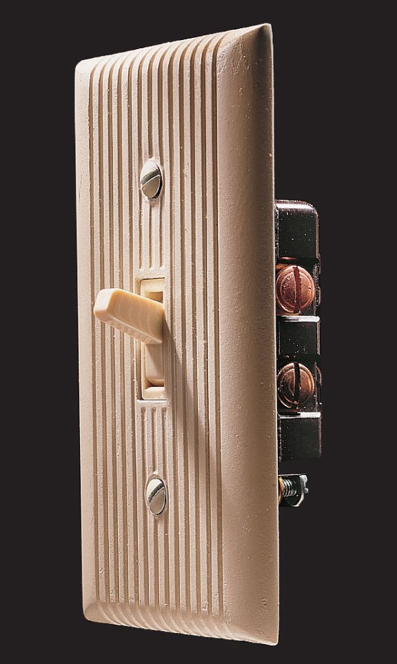
Toggle switches were introduced in the 1930s. This early design has a switch mechanism that is mounted in a ceramic housing sealed with a layer of insulating paper.
Toggle switches were improved during the 1950s and are now the most commonly used type. This switch type was the first to use a sealed plastic housing that protects the inner switch mechanism from dust and moisture.
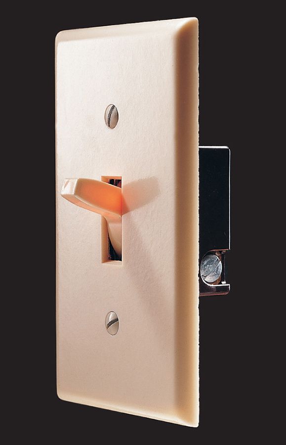
Mercury switches became common in the early 1960s. They conduct electrical current by means of a sealed vial of mercury. No longer manufactured for home use, old mercury switches are considered a hazardous waste.
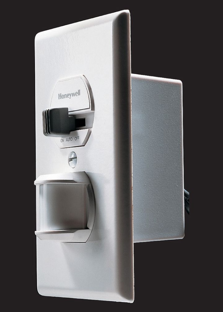
Electronic motion-sensor switches have an infrared eye that senses movement and automatically turns on lights when a person enters a room. Motion-sensor switches can provide added security against intruders.
![]() Types of Wall Switches
Types of Wall Switches
Wall switches are available in three general types. To re-connect or replace a switch, it is important to identify its type.
Single-pole switches are used to control a set of lights from one location. Three-way switches are used to control a set of lights from two different locations and are always installed in pairs. Four-way switches are used in combination with a pair of three-way switches to control a set of lights from three or more locations.
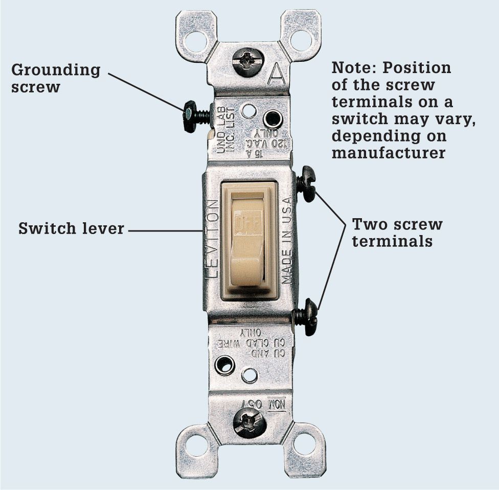
Identify switch types by counting the screw terminals. Single-pole switches have two screw terminals, three-way switches have three screw terminals, and four-way switches have four. Most switches include a grounding screw terminal, which is identified by its green color.
When replacing a switch, choose a new switch that has the same number of screw terminals as the old one. The location of the screws on the switch body varies depending on the manufacturer, but these differences will not affect the switch operation.
Whenever possible, connect switches using the screw terminals rather than push-in fittings. Some specialty switches (pages 94 to 97) have wire leads instead of screw terminals. They are connected to circuit wires with wire connectors.
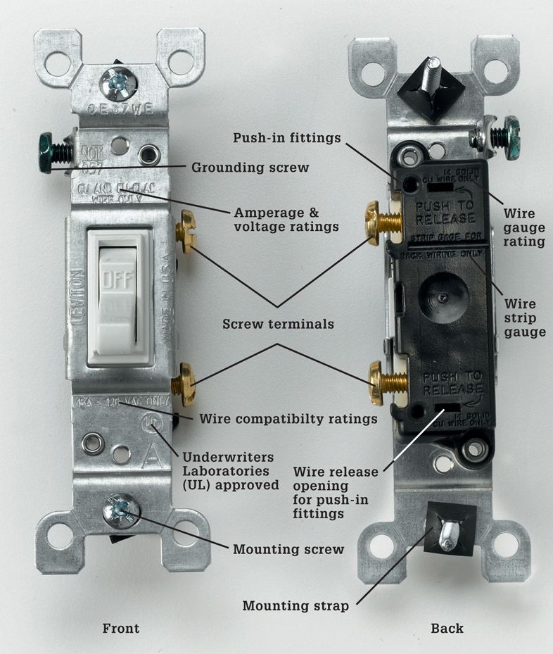
A wall switch is connected to circuit wires with screw terminals or with push-in fittings on the back of the switch. A switch may have a stamped strip gauge that indicates how much insulation must be stripped from the circuit wires to make the connections.
The switch body is attached to a metal mounting strap that allows it to be mounted in an electrical box. Several rating stamps are found on the strap and on the back of the switch. The abbreviation UL or UND. LAB. INC. LIST means that the switch meets the safety standards of the Underwriters Laboratories. Switches also are stamped with maximum voltage and amperage ratings. Standard wall switches are rated 15A or 125V. Voltage ratings of 110, 120, and 125 are considered to be identical for purposes of identification.
For standard wall switch installations, choose a switch that has a wire gauge rating of #12 or #14. For wire systems with solid-core copper wiring, use only switches marked COPPER, CU, or CO/ALR. For aluminum wiring, use only switches marked CO/ALR. Note that while CO/ALR switches and receptacles are approved by the National Electrical Code for use with aluminum wiring, the Consumer Products Safety Commission does not recommend using these. Switches and receptacles marked AL/CU can no longer be used with aluminum wiring, according to the National Electrical Code.
![]() Single-Pole Wall Switches
Single-Pole Wall Switches
A single-pole switch is the most common type of wall switch. It has ON-OFF markings on the switch lever and is used to control a set of lights, an appliance, or a receptacle from a single location. A single-pole switch has two screw terminals and a grounding screw. When installing a single-pole switch, check to make sure the ON marking shows when the switch lever is in the up position.
In a correctly wired single-pole switch, a hot circuit wire is attached to each screw terminal. However, the color and number of wires inside the switch box will vary, depending on the location of the switch along the electrical circuit.
If two cables enter the box, then the switch lies in the middle of the circuit. In this installation, both of the hot wires attached to the switch are black.
If only one cable enters the box, then the switch lies at the end of the circuit. In this installation (sometimes called a switch loop), one of the hot wires is black, but the other hot wire usually is white. A white hot wire should be coded with black tape or paint.
A single-pole switch is essentially an interruption in the black power supply wire that is opened or closed with the toggle. Single-pole switches are the simplest of all home wiring switches.
![]() Typical Single-Pole Switch Installations
Typical Single-Pole Switch Installations
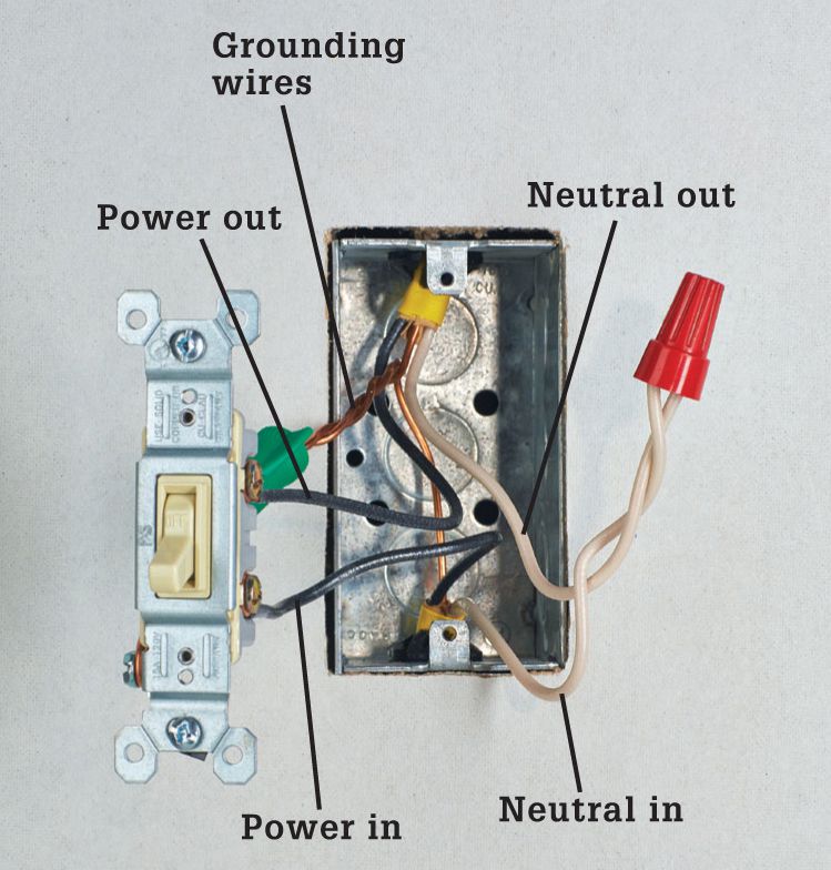
Two cables enter the box when a switch is located in the middle of a circuit. Each cable has a white and a black insulated wire, plus a bare copper grounding wire. The black wires are hot and are connected to the screw terminals on the switch. The white wires are neutral and are joined together with a wire connector. Grounding wires are pigtailed to the switch.
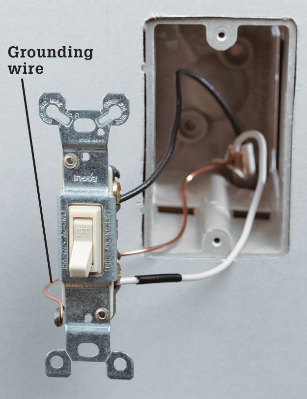
Old method: One cable enters the box when a switch is located at the end of a circuit. In this installation, both of the insulated wires are hot. The white wire should be labeled with black tape or paint to identify it as a hot wire. The grounding wire is connected to the switch grounding screw.
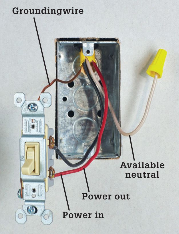
Code change: In new switch wiring, the white wire should not supply current to the switched device and a separate neutral wire should be available in the switch box.
![]() Three-Way Wall Switches
Three-Way Wall Switches
Three-way switches have three screw terminals and do not have ON-OFF markings. Three-way switches are always installed in pairs and are used to control a set of lights from two locations.
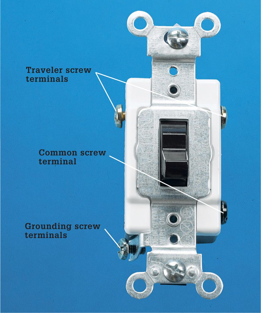
One of the screw terminals on a three-way switch is darker than the others. This screw is the common screw terminal. The position of the common screw terminal on the switch body may vary, depending on the manufacturer. Before disconnecting a three-way switch, always label the wire that is connected to the common screw terminal. It must be reconnected to the common screw terminal on the new switch.
The two lighter-colored screw terminals on a three-way switch are called the traveler screw terminals. The traveler terminals are interchangeable, so there is no need to label the wires attached to them.
Because three-way switches are installed in pairs, it sometimes is difficult to determine which of the switches is causing a problem. The switch that receives greater use is more likely to fail, but you may need to inspect both switches to find the source of the problem.
![]() Typical Three-Way Switch Installation
Typical Three-Way Switch Installation
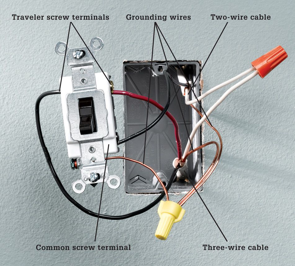
Two cables enter the box: one cable has two wires, plus a bare copper grounding wire; the other cable has three wires, plus a ground. The black wire from the two-wire cable is connected to the dark common screw terminal. The red and black wires from the three-wire cable are connected to the traveler screw terminals. The white neutral wires are joined together with a wire connector, and the grounding wires are pigtailed to the grounded metal box.
![]() How to Replace a Three-Way Wall Switch
How to Replace a Three-Way Wall Switch
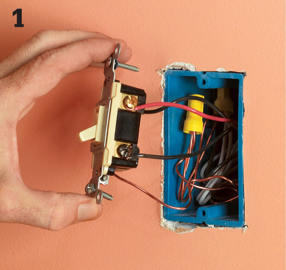
Turn off the power to the switch at the panel, and then remove the switch cover plate and mounting screws. Holding the mounting strap carefully, pull the switch from the box. Be careful not to touch the bare wires or screw terminals until they have been tested for power. Note: If you are installing a new switch circuit, you must provide a neutral conductor at the switch.
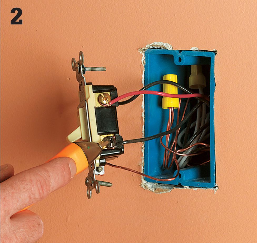
Test for power by touching one probe of the circuit tester to the grounded metal box or to the bare copper grounding wire and touching the other probe to each screw terminal. Tester should not glow. If it does, there is still power entering the box. Return to the panel, and turn off the correct circuit.
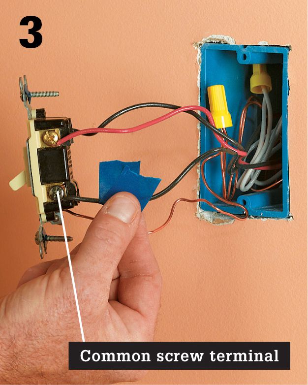
Locate the dark common screw terminal, and use masking tape to label the “common” wire attached to it. Disconnect wires and remove switch. Test the switch for continuity. If it tests faulty, buy a replacement. Inspect wires for nicks and scratches. If necessary, clip damaged wires and strip them.
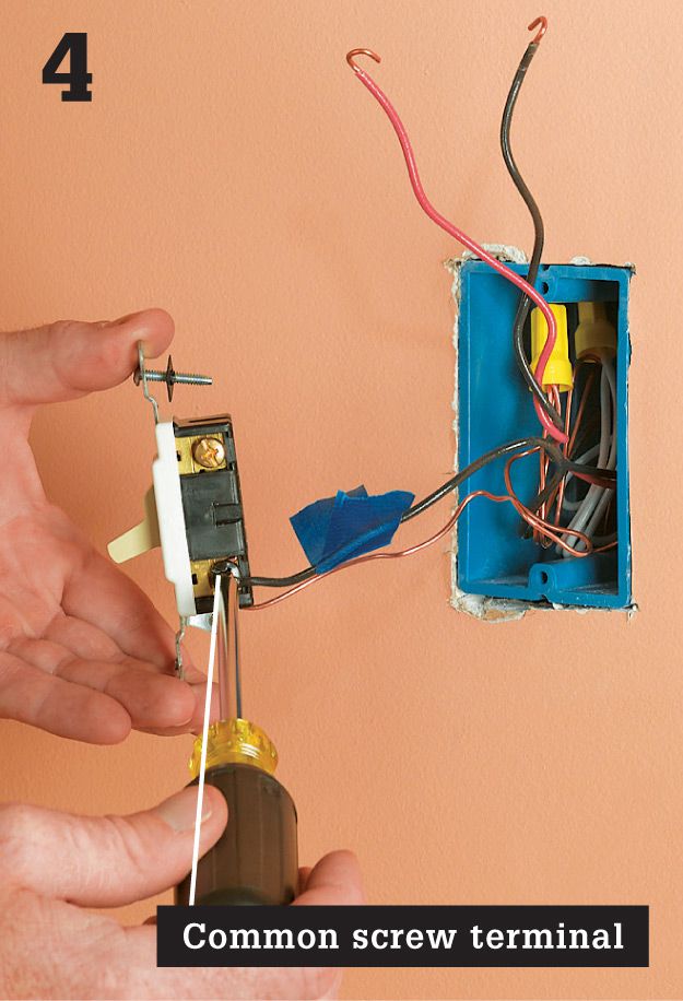
Connect the common wire to the dark common screw terminal on the switch. On most three-way switches, the common screw terminal is black. Or it may be labeled with the word COMMON stamped on the back of the switch. Reconnect the grounding screw, and connect it to the circuit grounding wires with a pigtail.
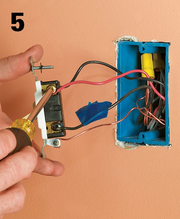
Connect the remaining two circuit wires to the screw terminals. These wires are interchangeable and can be connected to either screw terminal. Carefully tuck the wires into the box. Remount the switch, and attach the cover plate. Turn on the power at the panel.
![]() Four-Way Wall Switches
Four-Way Wall Switches
Four-way switches have four screw terminals and do not have ON-OFF markings. Four-way switches are always installed between a pair of three-way switches. This switch combination makes it possible to control a set of lights from three or more locations. Four-way switches are common in homes where large rooms contain multiple living areas, such as a kitchen opening into a dining room. Switch problems in a four-way installation can be caused by loose connections or worn parts in a four-way switch or in one of the three-way switches (facing page).
In a typical installation, there will be a pair of three-wire cables that enter the box for the four-way switch. With most switches, the white and red wires from one cable should be attached to the bottom or top pair of screw terminals, and the white and red wires from the other cable should be attached to the remaining pair of screw terminals. However, not all switches are configured the same way, and wiring configurations in the box may vary, so always study the wiring diagram that comes with the switch.
![]() Typical Four-Way Switch Installation
Typical Four-Way Switch Installation
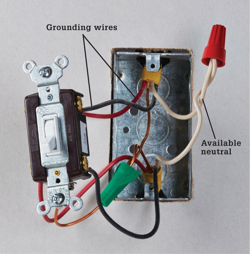
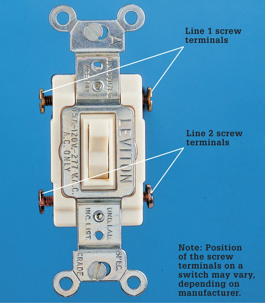
Four wires are connected to a four-way switch. The red and white wires from one cable are attached to the top pair of screw terminals, while the red and white wires from the other cable are attached to the bottom screw terminals. In new switch wiring, the white wire should not supply current to the switched device, and a separate neutral wire should be available in the switch box.
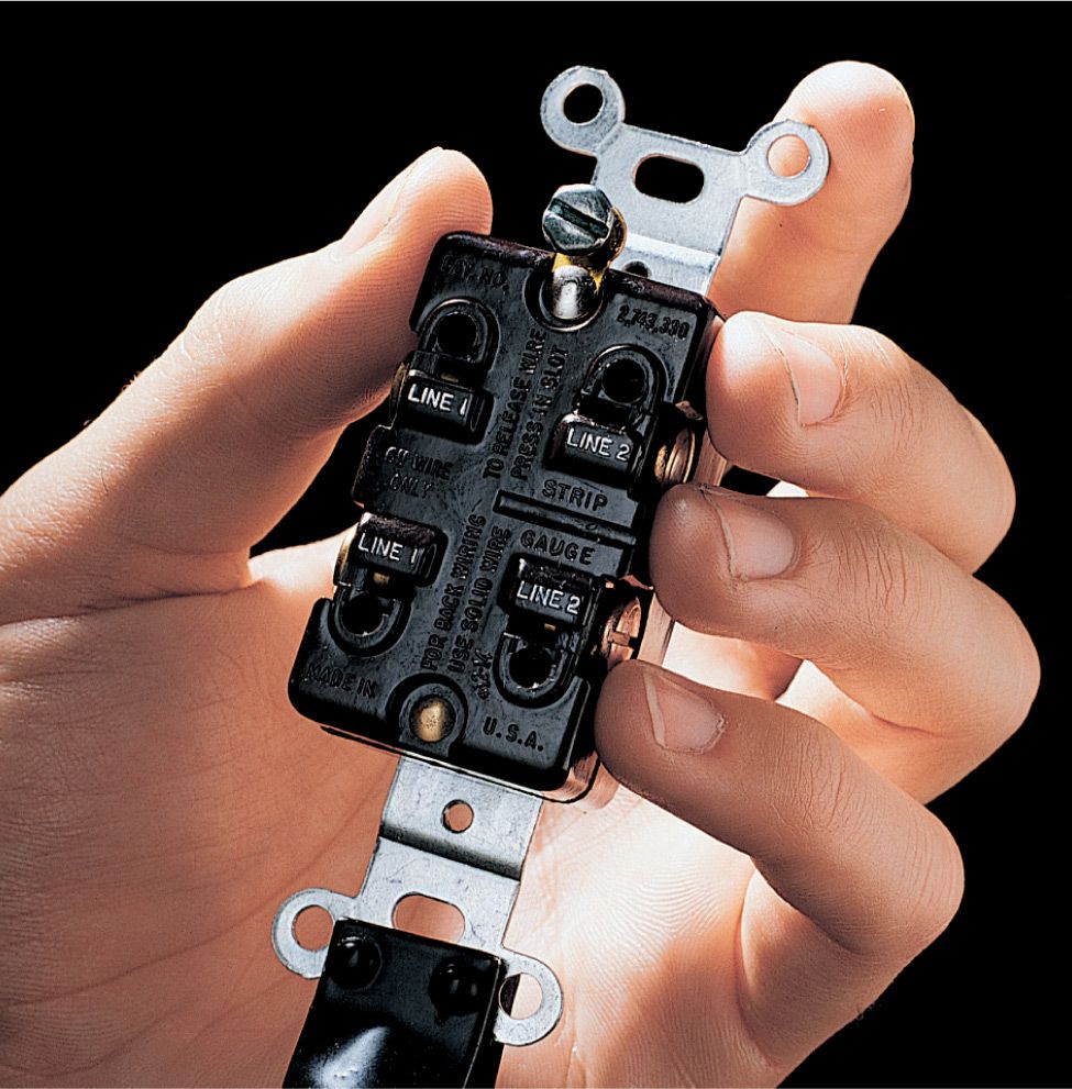
Switch variation: Some four-way switches have a wiring guide stamped on the back to help simplify installation. For the switch shown above, one pair of color-matched circuit wires will be connected to the screw terminals marked LINE 1, while the other pair of wires will be attached to the screw terminals marked LINE 2.
![]() How to Replace a Four-Way Wall Switch
How to Replace a Four-Way Wall Switch
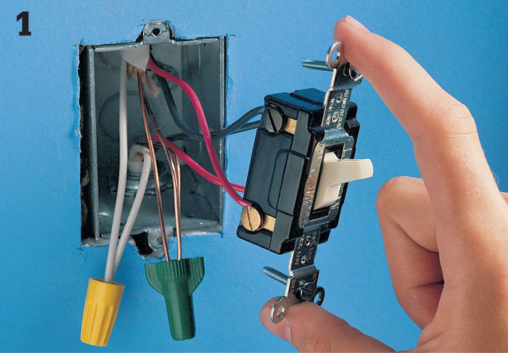
Turn off the power to the switch at the panel, and then remove the switch cover plate and mounting screws. Holding the mounting strap carefully, pull the switch from the box. Be careful not to touch any bare wires or screw terminals until they have been tested for power. Test for power by touching one probe of the neon circuit tester to the grounded metal box or bare copper grounding wire and touching the other probe to each of the screw terminals. The tester should not glow. If it does, there is still power entering the box. Return to the panel, and turn off the correct circuit.
Disconnect the wires and inspect them for nicks and scratches. If necessary, clip damaged wires and strip them. Test the switch for continuity (pages 98 to 101). Buy a replacement if the switch tests faulty.
Connect two wires from one incoming cable to the top set of screw terminals.
Attach remaining wires to the other set of screw terminals. Pigtail the grounding wires to the grounding screw. Carefully tuck the wires inside the switch box, and then remount the switch and cover plate. Turn on power at the panel.
![]() Double Switches
Double Switches
A double switch has two switch levers in a single housing. It is used to control two light fixtures or appliances from the same switch box.
In most installations, both halves of the switch are powered by the same circuit. In these single-circuit installations, three wires are connected to the double switch. One wire, called the feed wire (which is hot), supplies power to both halves of the switch. The other wires, called the switch leg, carry power out to the individual light fixtures or appliances.
In rare installations, each half of the switch is powered by a separate circuit. In these separate-circuit installations, four wires are connected to the switch, and the metal connecting tab joining two of the screw terminals is removed (see photo below).
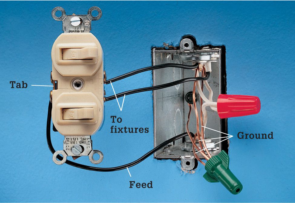
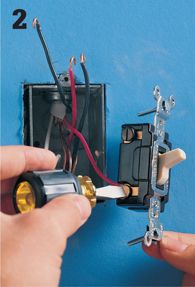
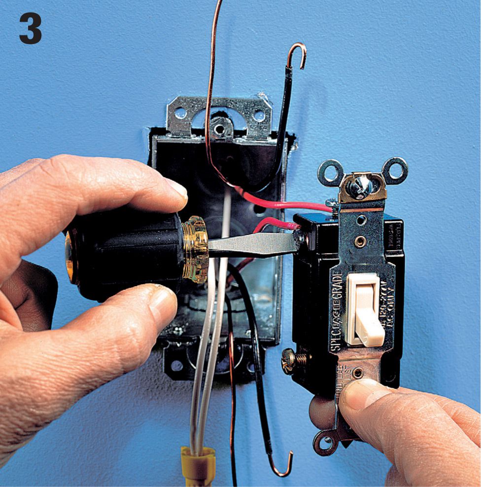
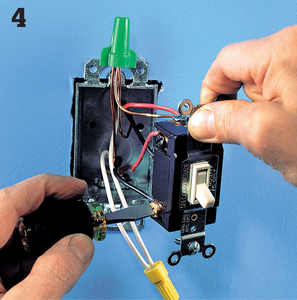
Single-circuit wiring: Three black wires are attached to the switch. The black feed wire bringing power into the box is connected to the side of the switch that has a connecting tab. The wires carrying power out to the light fixtures or appliances are connected to the side of the switch that does not have a connecting tab. The white neutral wires are connected together with a wire connector.
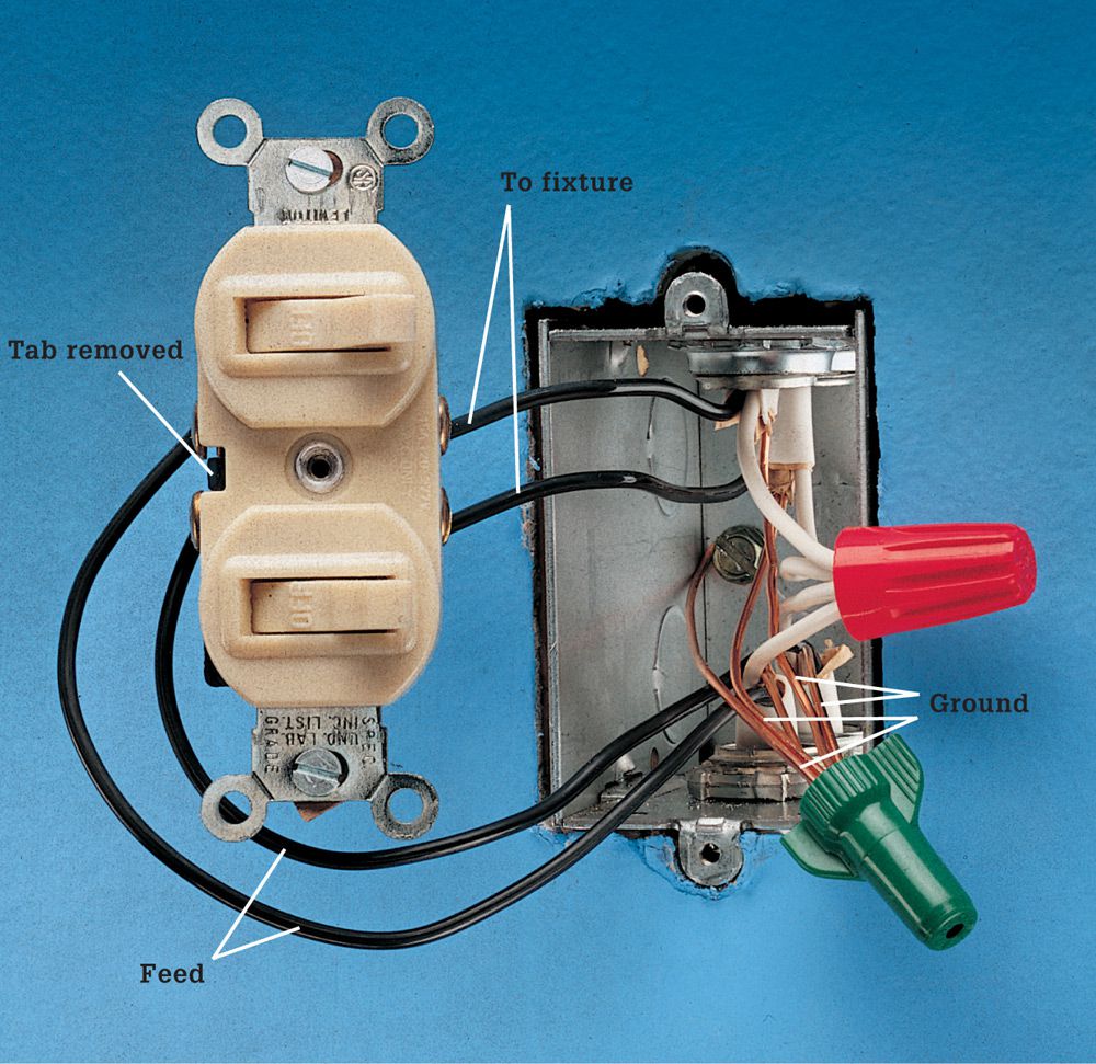
Separate-circuit wiring: Four black wires are attached to the switch. Feed wires from the power source are attached to the side of the switch that has a connecting tab, and the connecting tab is removed (photo, right). Wires carrying power from the switch to light fixtures or appliances are connected to the side of the switch that does not have a connecting tab. White neutral wires are connected together with a wire connector.
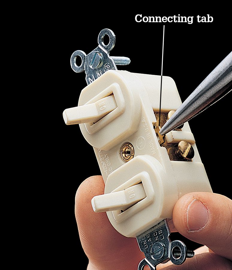
Remove the connecting tab on a double switch when wired in a separate-circuit installation. The tab can be removed with needlenose pliers or a screwdriver.
![]() Pilot-Light Switches
Pilot-Light Switches
A pilot-light switch has a built-in bulb that glows when power flows through the switch to a light fixture or appliance. Pilot-light switches often are installed for convenience if a light fixture or appliance cannot be seen from the switch location. Basement lights, garage lights, and attic exhaust fans frequently are controlled by pilot-light switches.
A pilot-light switch requires a neutral wire connection. A switch box that contains a single two-wire cable has only hot wires and cannot be fitted with a pilot-light switch.
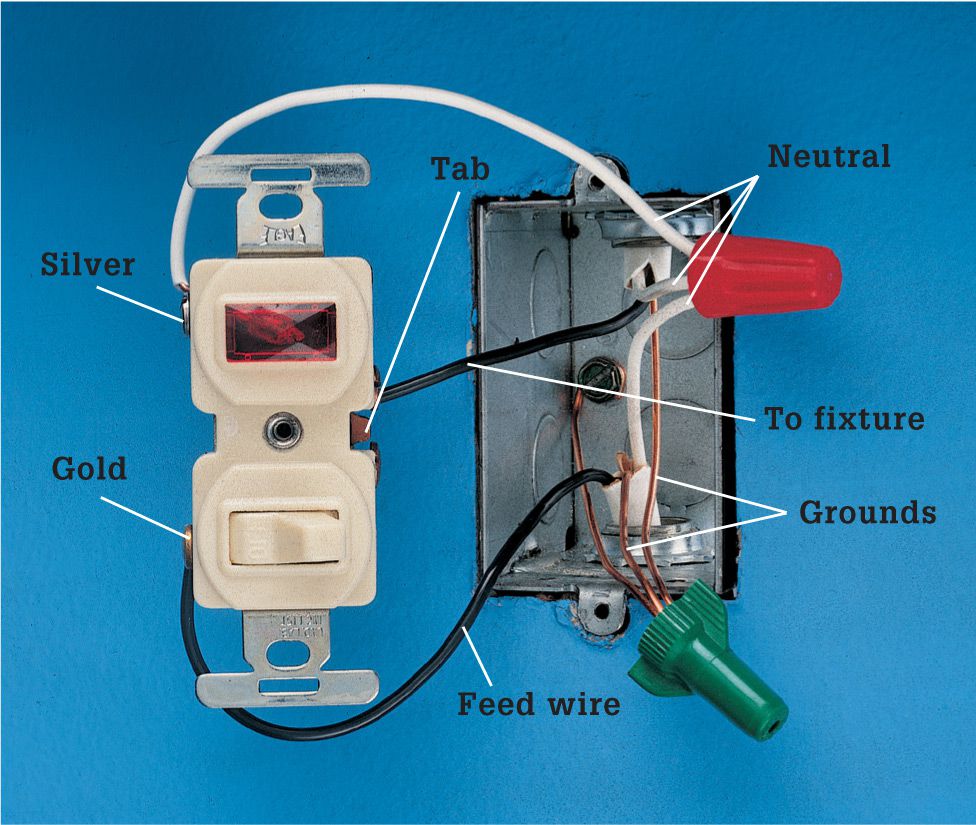
Pilot-light switch wiring: Three wires are connected to the switch. One black wire is the feed wire that brings power into the box. It is connected to the brass (gold) screw terminal on the side of the switch that does not have a connecting tab. The white neutral wires are pigtailed to the silver screw terminal. The black wire carrying power out to a light fixture or appliance is connected to the screw terminal on the side of the switch that has a connecting tab.
![]() Switch/Receptacles
Switch/Receptacles
A switch/receptacle combines a grounded receptacle with a single-pole wall switch. In a room that does not have enough wall receptacles, electrical service can be improved by replacing a single-pole switch with a switch/receptacle.
A switch/receptacle requires a neutral wire connection. A switch box that contains a single two-wire cable has only hot wires and cannot be fitted with a switch/receptacle.
A switch/receptacle can be installed in one of two ways. In the most common installations, the receptacle is hot even when the switch is off (photo, right).
In rare installations, a switch/receptacle is wired so the receptacle is hot only when the switch is on. In this installation, the hot wires are reversed, so that the feed wire is attached to the brass screw terminal on the side of the switch that does not have a connecting tab.
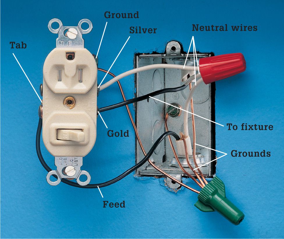
Switch/receptacle wiring: Three wires are connected to the switch/receptacle. One of the hot wires is the feed wire that brings power into the box. It is connected to the side of the switch that has a connecting tab. The other hot wire carries power out to the light fixture or appliance. It is connected to the brass screw terminal on the side that does not have a connecting tab. The white neutral wire is pigtailed to the silver screw terminal. The grounding wires must be pigtailed to the green grounding screw on the switch/receptacle and to the grounded metal box.
![]() Specialty Switches
Specialty Switches
Your house may have several types of specialty switches. Dimmer switches (pages 96 to 97) are used frequently to control light intensity in dining and recreation areas. Timer switches and time-delay switches (below) are used to control light fixtures and exhaust fans automatically. Electronic switches provide added convenience and home security, and they are easy to install. Electronic switches are durable, and they rarely need replacement.
Most specialty switches have preattached wire leads instead of screw terminals and are connected to circuit wires with wire connectors. Some motor-driven timer switches require a neutral wire connection and cannot be installed in switch boxes that have only one cable with two hot wires. It is precisely due to the rise in popularity of “smart” switches that the NEC Code was changed in 2014 to require an available neutral wire in newly-installed switch boxes.
If a specialty switch is not operating correctly, you may be able to test it with a continuity tester. Timer switches and time-delay switches can be tested for continuity, but dimmer switches cannot be tested. With electronic switches, the manual switch can be tested for continuity, but the automatic features cannot be tested.
![]() Timer Switches
Timer Switches
Countdown timer switches can be set to turn lights or fans on and off automatically once each day. They are commonly used to control outdoor light fixtures.
Timer switches have three preattached wire leads. The black wire lead is connected to the hot feed wire that brings power into the box, and the red lead is connected to the wire carrying power out to the light fixture. The remaining wire lead is the neutral lead. It must be connected to any neutral circuit wires. A switch box that contains only one cable has no neutral wires, so it cannot be fitted with a timer switch.
After a power failure, the dial on a timer switch must be reset to the proper time.
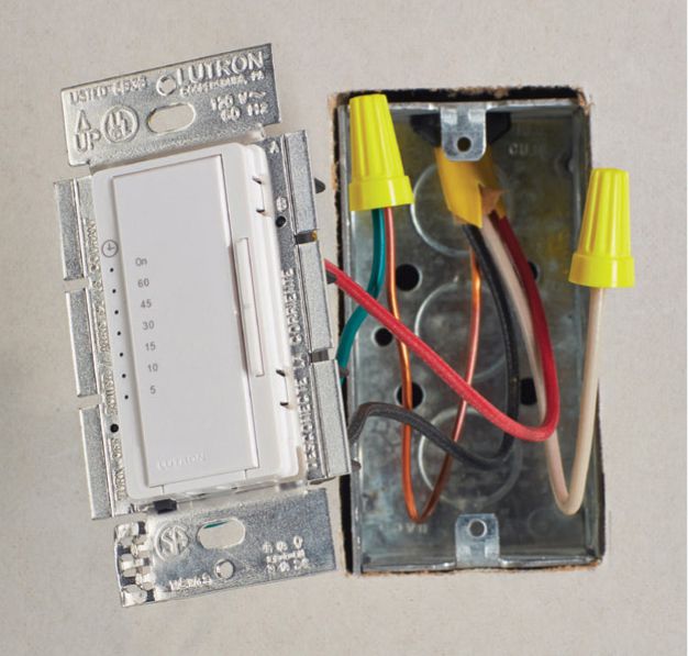
Countdown timer switch. This rocker-type switch gives you the option to easily program the switch to shut off after a specified time: from 5 to 60 minutes. Garage lights or basement lights are good applications: anywhere you want the light to stay on long enough to allow you to exit, but not to stay on indefinitely. These switches often are used to control vent fans.
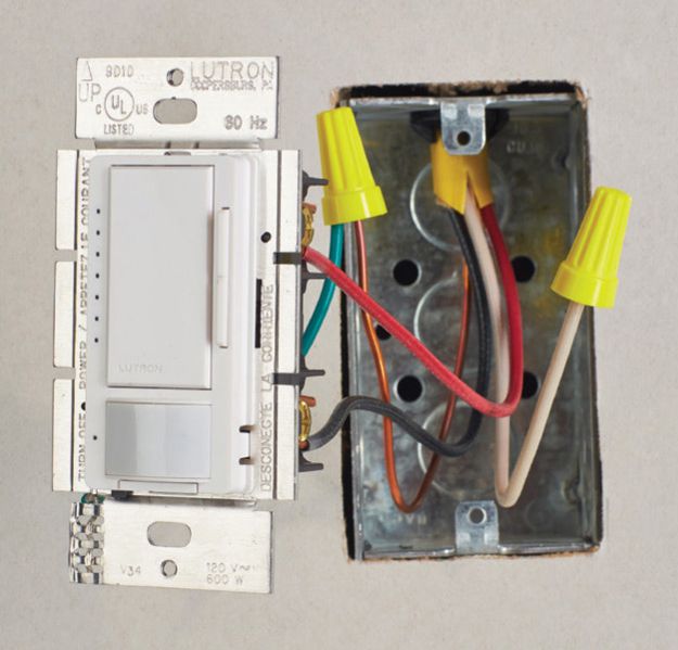
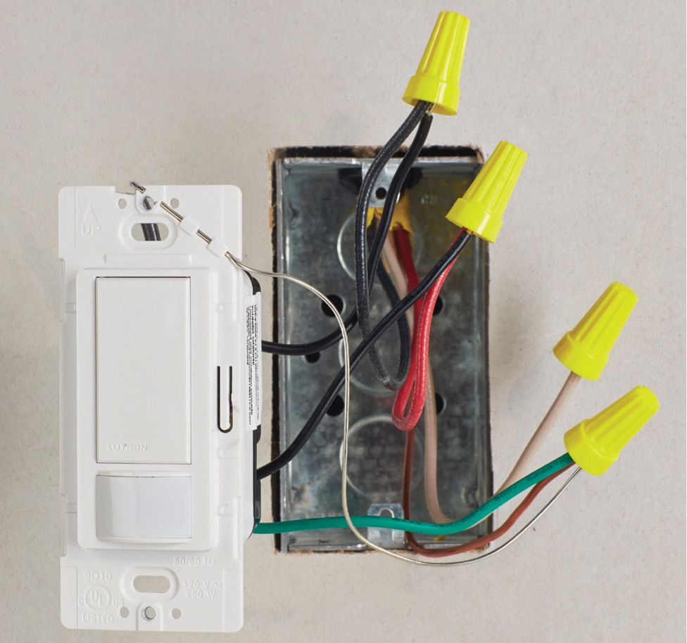
Occupancy sensor. Many smart switches incorporate a motion detector that will switch the lights on if they sense movement in the room and will also shut them off when no movement is detected for a period of time. The model shown above also has a dimmer function for further energy savings.
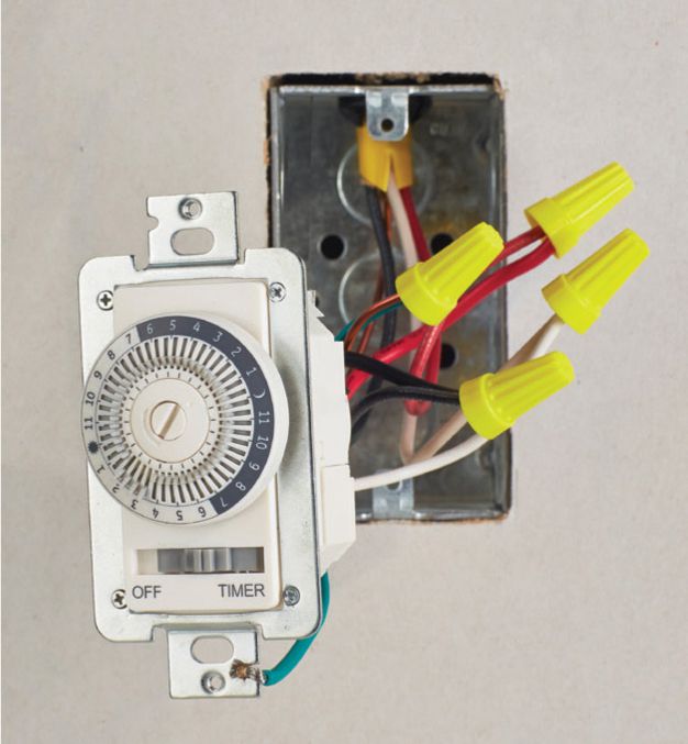
Programmable timer switch. A dial-type timer allows you to program the switch to turn on for specific time periods at designated times of day within a 24-hour cycle. Security lights, space heaters, towel warmers, and radiant floors are typical applications.
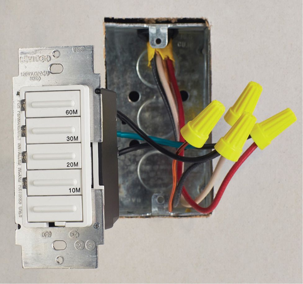
Preset timer switch. This lets you turn on lights, heat lamps, and other loads for a designated amount of time (10 to 60 minutes) with one easy push of a button. The green LED at the bottom of this unit provides a readout of how much time is left before the switch shuts off. The model shown is not compatible with fluorescent ballasts.
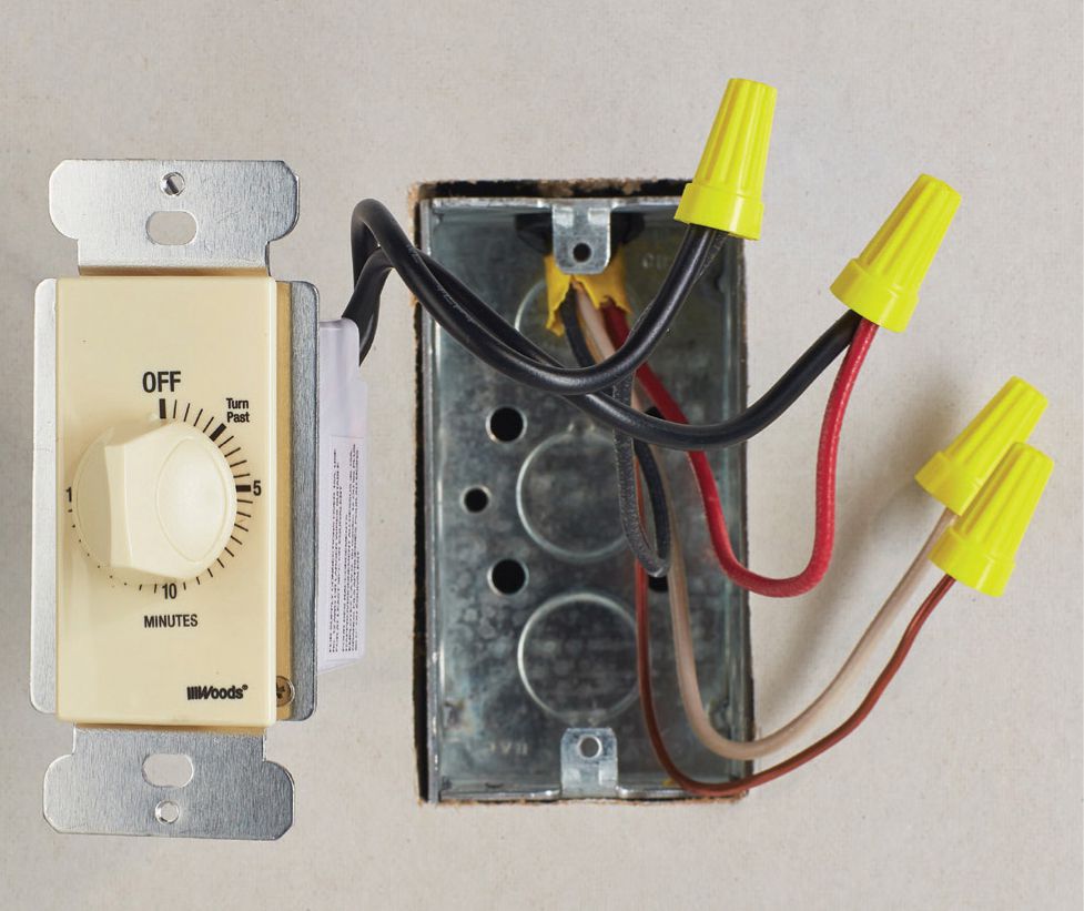
Spring-wound timer switch. A relatively simple device, this timer switch functions exactly like a kitchen timer, employing a hand-turned dial to and spring mechanism to shut the switch off in increments up to 15 minutes.
Daylight sensor switch. This switch automatically turns on when light levels drop below a proscribed level. It can also be programmed as an occupancy sensor to shut off when the room is vacant and turn on when the room is entered.
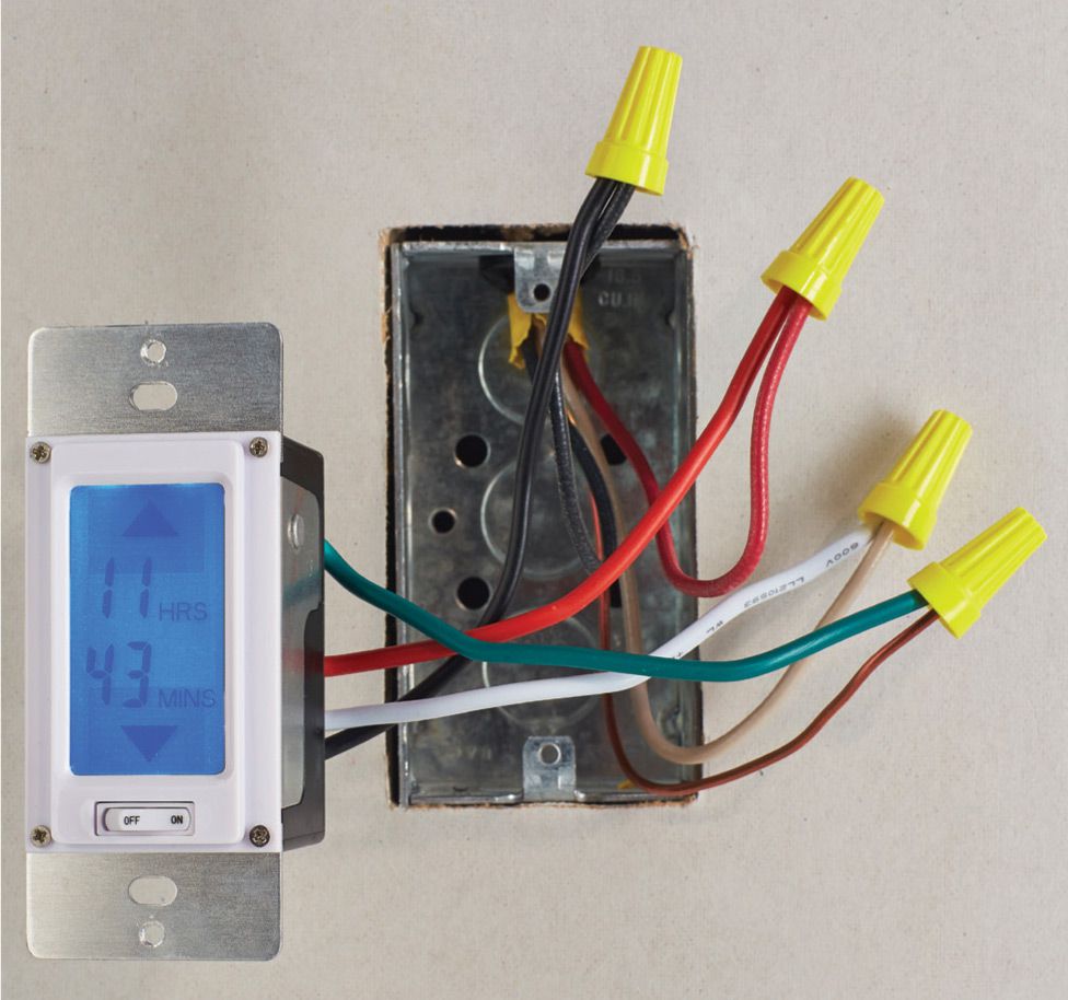
Backlit countdown timer. This digital switch lets you program lights or other devices to stay on for up to 24 hours and then shut off automatically. The backlit, LED readout gives a countdown, in minutes, of the amount of time left in the “on” cycle. Up and down buttons let you raise or lower the remaining time easily, and a manual override button will shut off the switch until it is turned back on.
![]() Dimmer Switches
Dimmer Switches
A dimmer switch makes it possible to vary the brightness of a light fixture. Dimmers are often installed in dining rooms, recreation areas, or bedrooms.
Any standard single-pole switch can be replaced with a dimmer, as long as the switch box is of adequate size. Dimmer switches have larger bodies than standard switches. They also generate a small amount of heat that must dissipate. For these reasons, dimmers should not be installed in undersized electrical boxes or in boxes that are crowded with circuit wires. Always follow the manufacturer’s specifications for installation.
In lighting configurations that use three-way switches (pages 88 to 89), buy a packaged pair of three-way dimmers designed to work together.
Dimmer switches are available in several styles (see photo, right). All types have wire leads instead of screw terminals, and they are connected to circuit wires using wire connectors. Some types have a green grounding lead that should be connected to the grounded metal box or to the bare copper grounding wires. Until very recently, dimmers were designed to work only with incandescent lamps. They may not work well, or may not work at all, with CFL and LED lamps. When replacing incandescent lamps with CFL and LED lamps, make sure the new lamps are designed to work with older dimmers. When replacing dimmers, make sure the new dimmers are designed to work with CFL and LED lamps.
Tools & Materials ![]()
Screwdriver
Circuit tester
Needlenose pliers
Wire connectors
Masking tape
Tip: Automatic dimmers ![]()
An automatic dimmer has an electronic sensor that adjusts the light fixture to compensate for the changing levels of natural light. An automatic dimmer also can be operated manually. For another example, see page 95, lower left.
![]() Switch Action Options
Switch Action Options
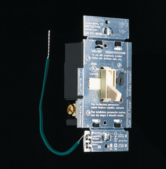
Toggle-type dimmers resemble standard switches. Toggle dimmers are available in both single-pole and three-way designs. The model shown supports incandescent, fluorescent, and LED dimmable blubs.
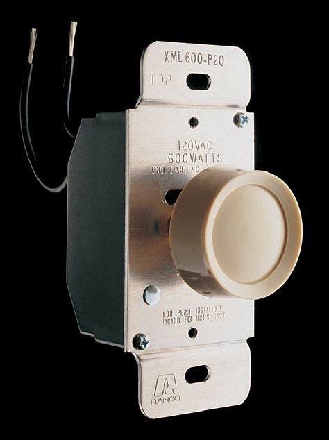
Dial-type dimmers are the most common style. rotating the dial changes the light intensity.
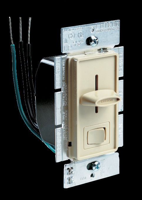
Slide-action dimmers have illuminated faces that make the switch easy to locate in the dark.
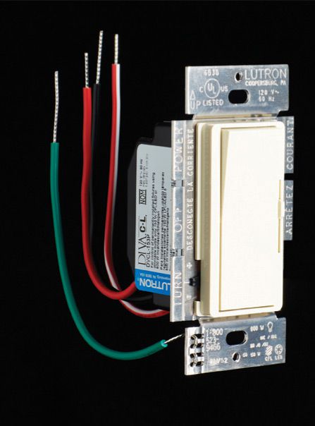
Rocker type switches control dimmable incandescent, fluorescent, LED, or halogen bulbs.
![]() How to Install a Dimmer Switch
How to Install a Dimmer Switch
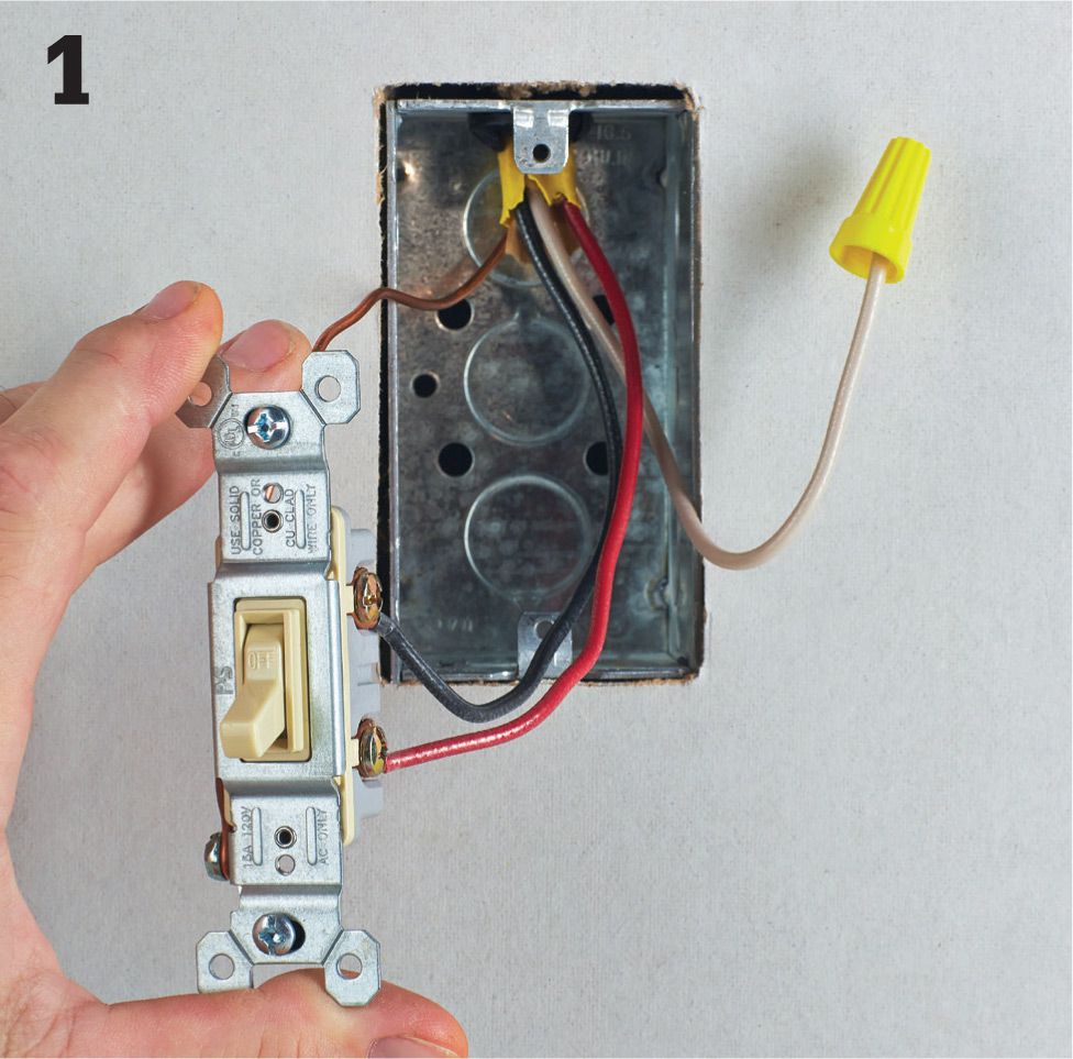
Turn off power to the switch at the panel, and then remove the cover plate and mounting screws. Holding the mounting straps carefully, pull the switch from the box. Be careful not to touch bare wires or screw terminals until they have been tested for power. In new switch wiring, the white wire should not supply current to the switched device, and a separate neutral wire should be available in the switch box.
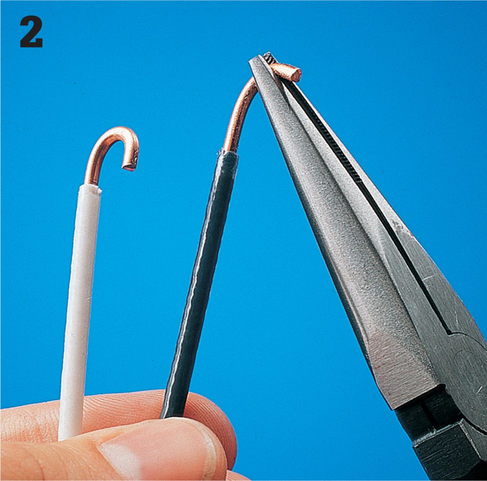
Disconnect the circuit wires and remove the switch. Straighten the circuit wires, and clip the ends, leaving about 1/2" of the bare wire end exposed.
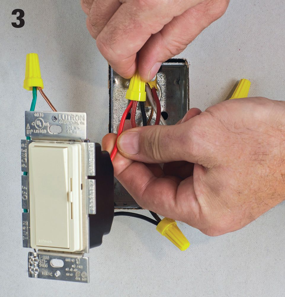
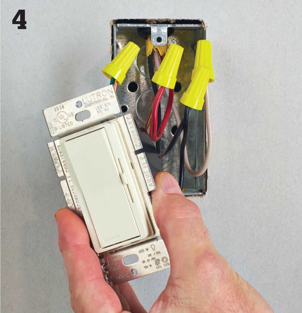
Connect the wire leads on the dimmer switch to the circuit wires using wire connectors. The switch leads are interchangeable and can be attached to either of the two circuit wires.
A three-way dimmer has an additional wire lead. This “common” lead is connected to the common circuit wire. When replacing a standard three-way switch with a dimmer, the common circuit wire is attached to the darkest screw terminal on the old switch. In new switch wiring, the white wire should not supply current to the switched device, and a separate neutral wire should be available in the switch box.
![]() Testing Switches
Testing Switches
Aswitch that does not work properly may have worn or broken internal parts. Test switches with a battery-operated continuity tester. The continuity tester detects any break in the metal pathway inside the switch. Replace the switch if the continuity tester shows the switch to be faulty.
Never use a continuity tester on wires that might carry live current. Always shut off the power and disconnect the switch before testing for continuity.
Some specialty switches, such as dimmers, cannot be tested for continuity. Electronic switches can be tested for manual operation using a continuity tester, but the automatic operation of these switches cannot be tested.
![]() How to Test a Single-Pole Wall Switch
How to Test a Single-Pole Wall Switch

Attach the clip of the tester to one of the screw terminals. Touch the tester probe to the other screw terminal. Flip the switch lever from ON to OFF. If the switch is good, the tester glows when the lever is ON but not when it’s OFF.
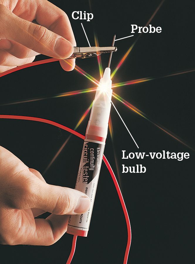
A continuity tester uses battery-generated current to test the metal pathways running through switches and other electrical fixtures. Always “test” the tester before use. Touch the tester clip to the metal probe. The tester should glow. If not, then the battery or lightbulb is dead and must be replaced.
![]() How to Test a Three-Way Wall Switch
How to Test a Three-Way Wall Switch
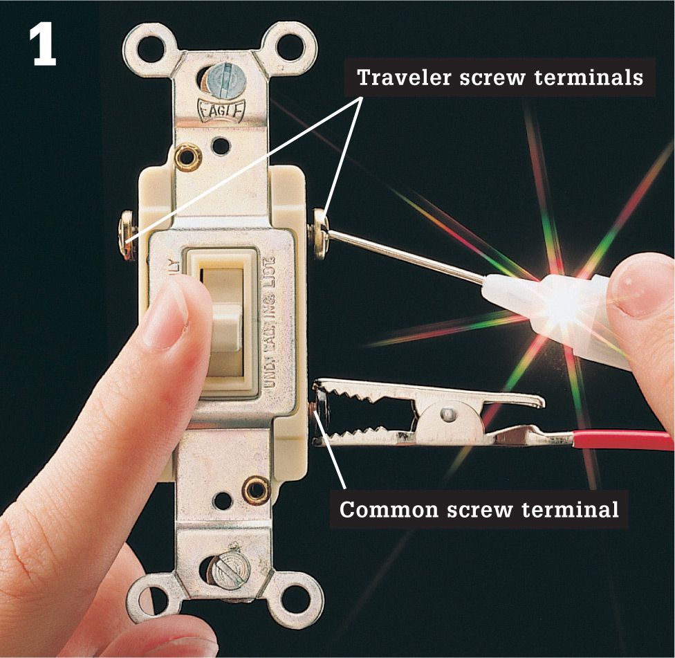
Attach the tester clip to the dark common screw terminal. Touch the tester probe to one of the traveler screw terminals, and flip the switch lever back and forth. If the switch is good, the tester should glow when the lever is in one position, but not both.
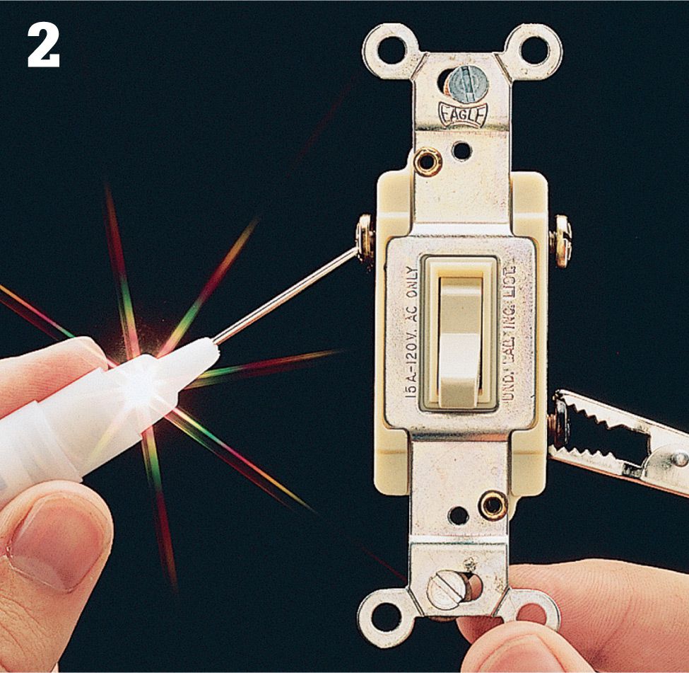
Touch the probe to the other traveler screw terminal, and flip the switch lever back and forth. If the switch is good, the tester will glow only when the switch lever is in the position opposite from the positive test in step 1.
![]() How to Test a Four-Way Wall Switch
How to Test a Four-Way Wall Switch
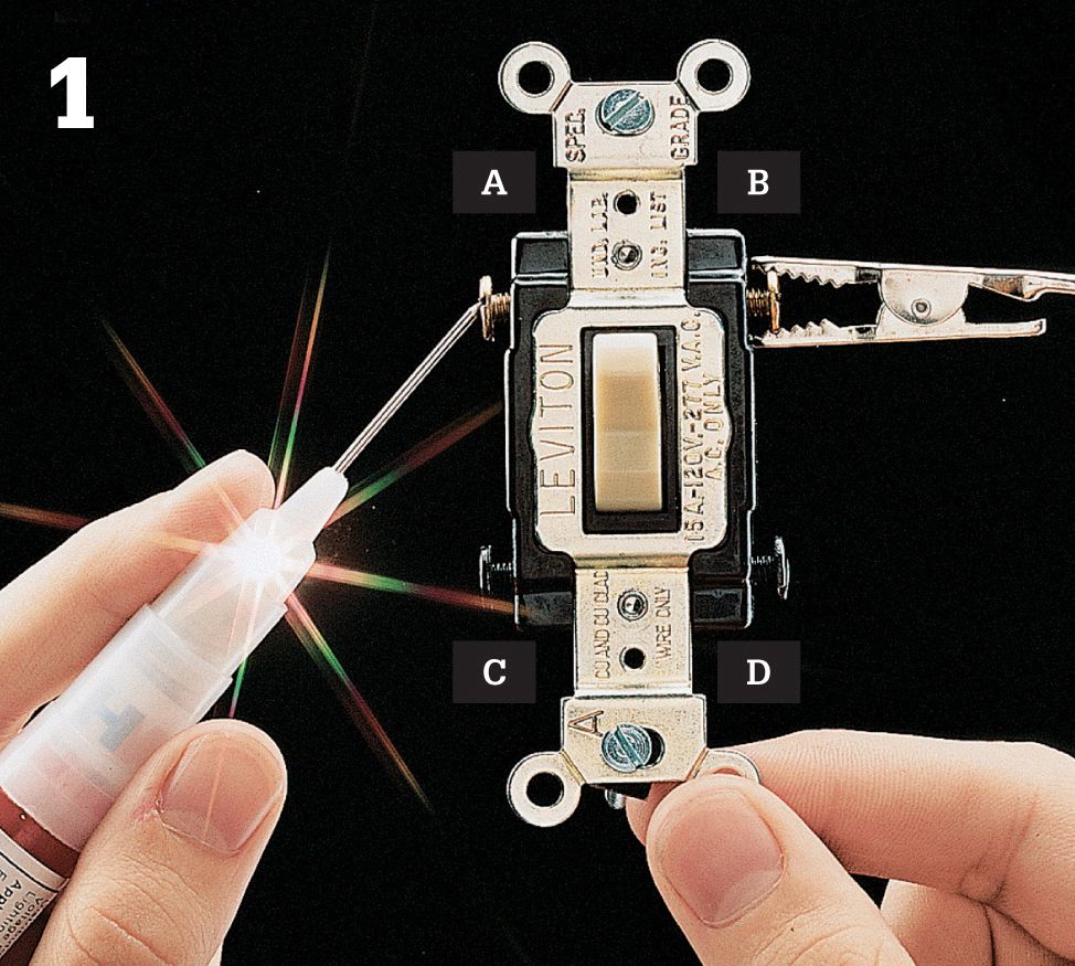
Test the switch by touching the probe and clip of the continuity tester to each pair of screw terminals (A-B, C-D, A-D, B-C, A-C, B-D). The test should show continuous pathways between the two different pairs of screw terminals. Flip the lever to the opposite position, and repeat the test. It should show continuous pathways between two different pairs of screw terminals.
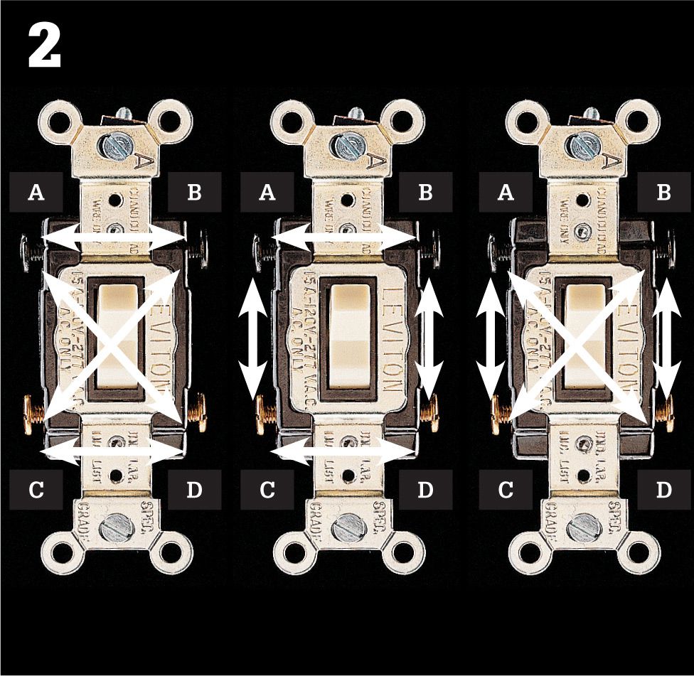
If the switch is good, the test will show a total of four continuous pathways between screw terminals—two pathways for each lever position. If not, then the switch is faulty and must be replaced. (The arrangement of the pathways may differ, depending on the switch manufacturer. The photo above shows the three possible pathway arrangements.)
![]() How to Test a Pilot-Light Switch
How to Test a Pilot-Light Switch
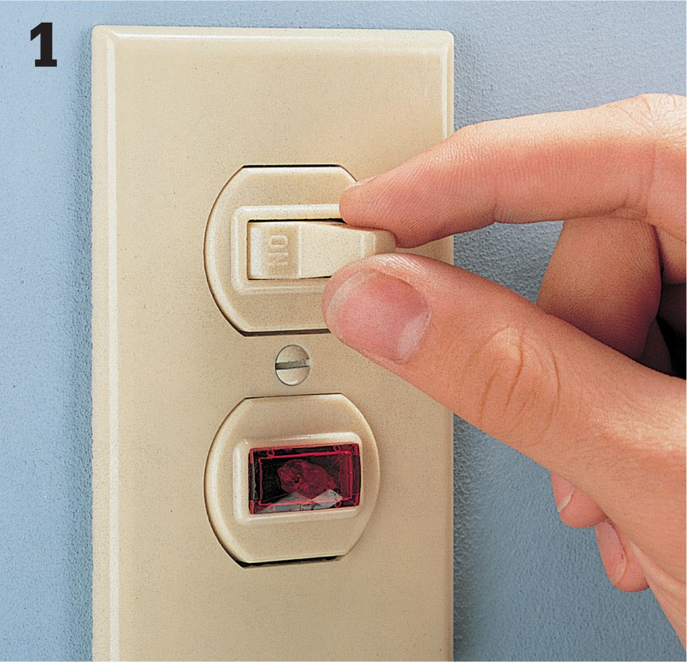
Test the pilot light by flipping the switch lever to the ON position. Check to see if the light fixture or appliance is working. If the pilot light does not glow even though the switch operates the light fixture or appliance, then the pilot light is defective and the unit must be replaced.
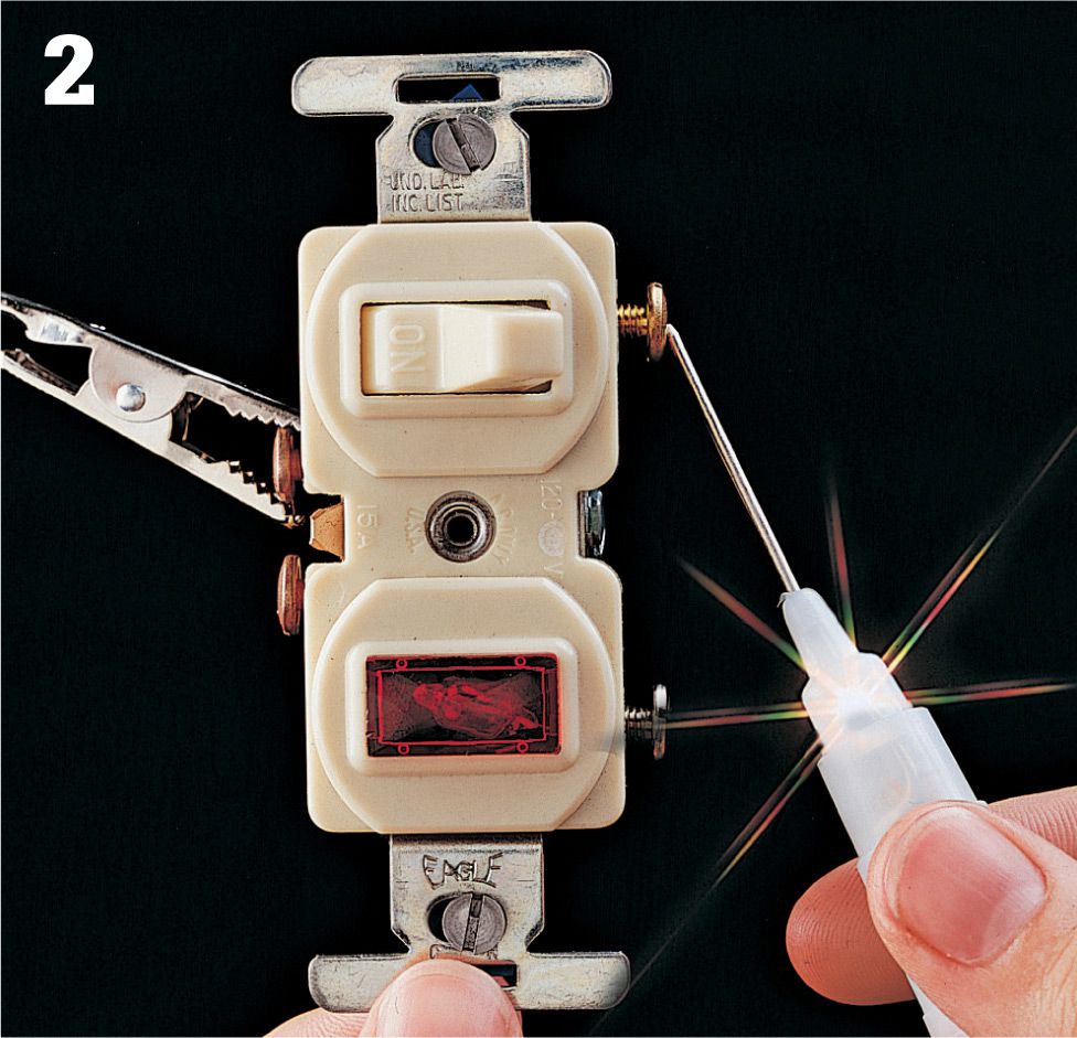
Test the switch by disconnecting the unit. With the switch lever in the ON position, attach the tester clip to the top screw terminal on one side of the switch. Touch the tester probe to the top screw terminal on the opposite side of the switch. If the switch is good, the tester will glow when switch is ON but not when OFF.
![]() How to Test a Timer Switch
How to Test a Timer Switch
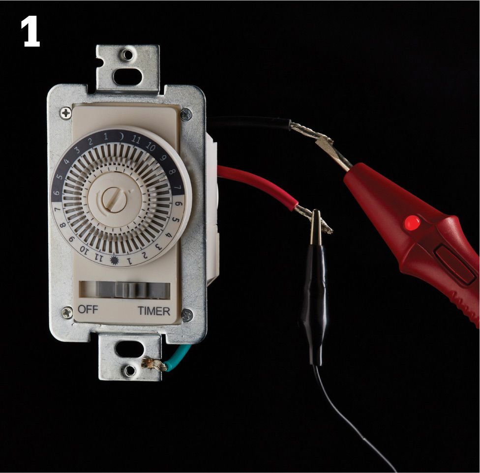
Attach the tester clip to the red wire lead on the timer switch, and touch the tester probe to the black hot lead. Rotate the timer dial clockwise until the ON tab passes the arrow marker. The tester should glow. If it does not, the switch is faulty and must be replaced.
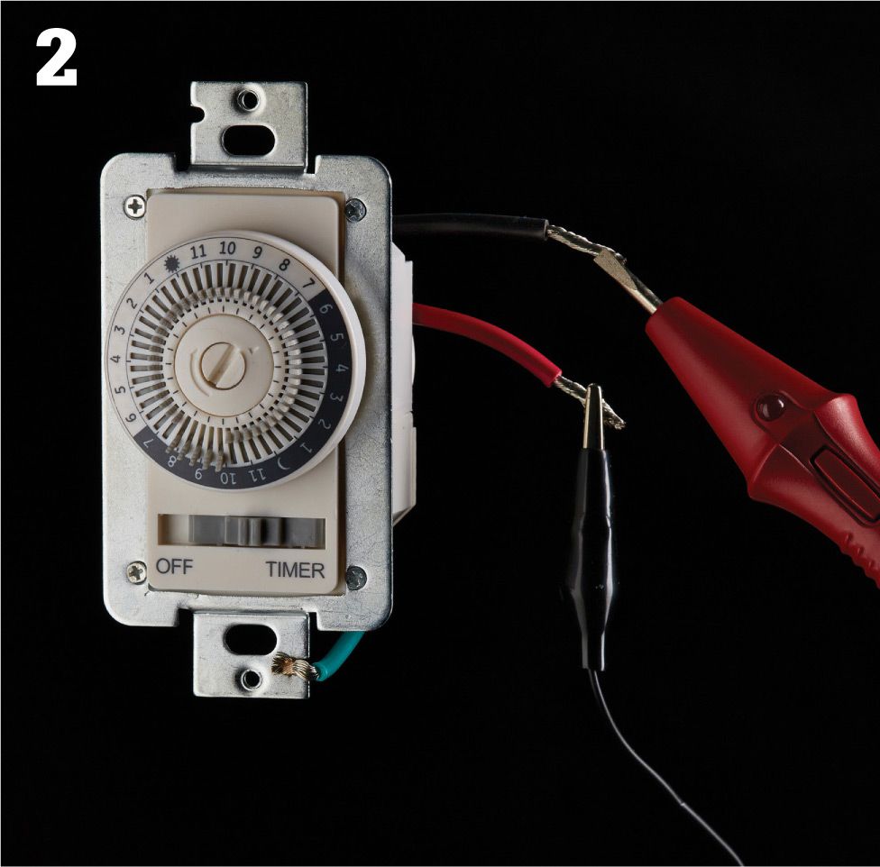
Rotate the dial clockwise until the OFF tab passes the arrow marker. The tester should not glow. If it does, the switch is faulty and must be replaced.
![]() How to Test a Switch/Receptacle
How to Test a Switch/Receptacle
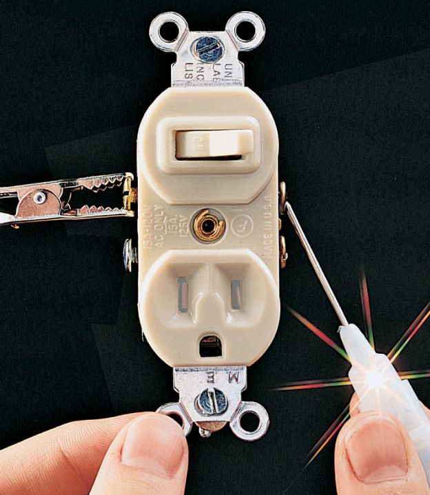
Attach the tester clip to one of the top screw terminals. Touch the tester probe to the top screw terminal on the opposite side. Flip the switch lever from ON to OFF position. If the switch is working correctly, the tester will glow when the switch lever is ON but not when it’s OFF.
![]() How to Test a Double Switch
How to Test a Double Switch
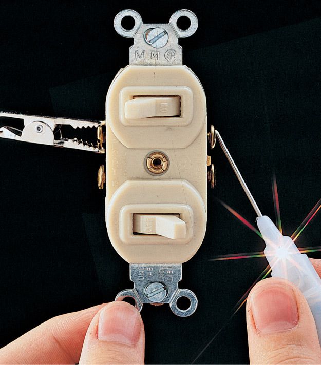
Test each half of the switch by attaching the tester clip to one screw terminal and touching the probe to the opposite side. Flip the switch lever from ON to OFF position. If the switch is good, the tester glows when the switch lever is ON but not when it’s OFF. Repeat the test with the remaining pair of screw terminals. If either half tests faulty, replace the unit.
![]() How to Test a Time-Delay Switch
How to Test a Time-Delay Switch
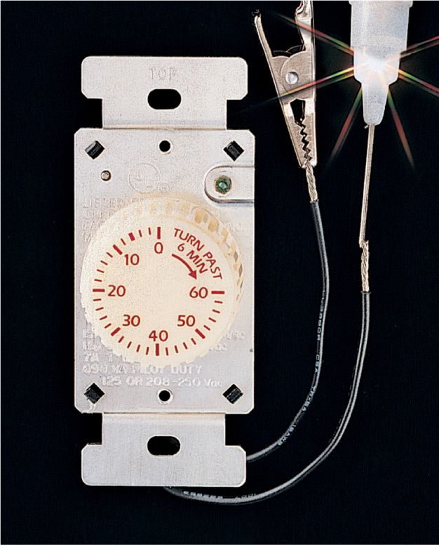
Attach the tester clip to one of the wire leads, and touch the tester probe to the other lead. Set the timer for a few minutes. If the switch is working correctly, the tester will glow until the time expires.
![]() How to Test Manual Operation of Electronic Switches
How to Test Manual Operation of Electronic Switches
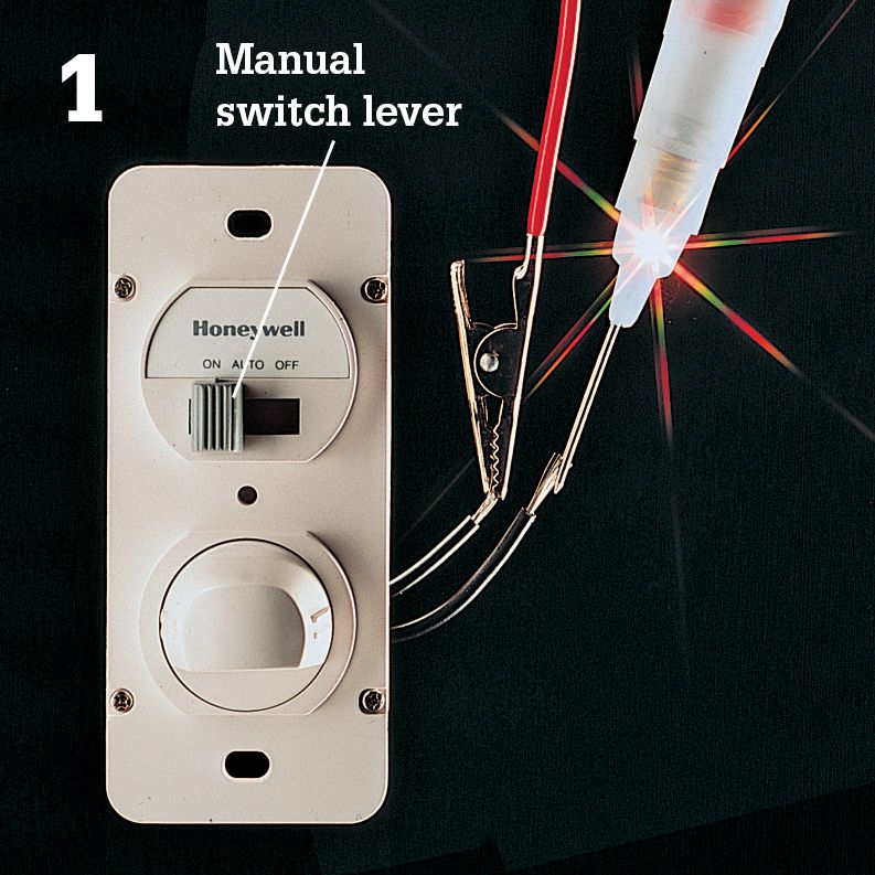
Automatic switch: Attach the tester clip to a black wire lead, and touch the tester probe to the other black lead. Flip the manual switch lever from ON to OFF position. If the switch is working correctly, the tester will glow when the switch lever is ON but not when it’s OFF.
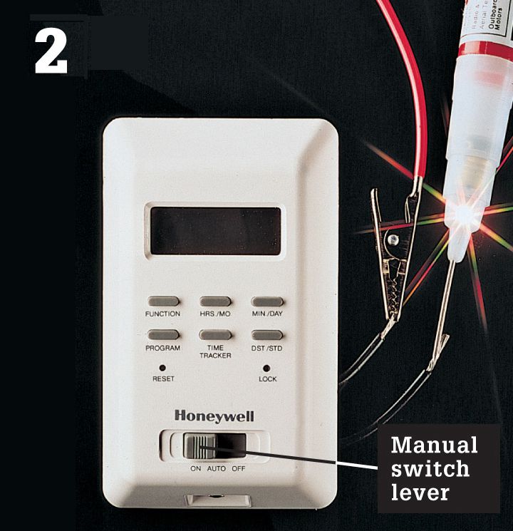
Programmable switch: Attach the tester clip to a wire lead, and touch the tester probe to the other lead. Flip the manual switch lever from ON to OFF position. If the switch is working correctly, the tester will glow when the switch lever is ON but not when it’s OFF.
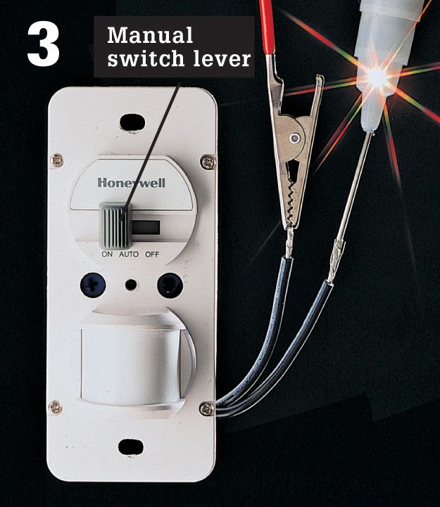
Motion-sensor switch: Attach the tester clip to a wire lead, and touch the tester probe to the other lead. Flip the manual switch lever from ON to OFF position. If the switch is working correctly, the tester will glow when the switch lever is ON but not when it’s OFF.