The Car Hacker's Handbook: A Guide for the Penetration Tester - Craig Smith (2016)
Chapter 5. REVERSE ENGINEERING THE CAN BUS
In order to reverse engineer the CAN bus, we first have to be able to read the CAN packets and identify which packets control what. That said, we don’t need to be able to access the official diagnostic CAN packets because they’re primarily a read-only window. Instead, we’re interested in accessing all the other packets that flood the CAN bus. The rest of the nondiagnostic packets are the ones that the car actually uses to perform actions. It can take a long time to grasp the information contained in these packets, but that knowledge can be critical to understanding the car’s behavior.
Locating the CAN Bus
Of course, before we can reverse the CAN bus, we need to locate the CAN. If you have access to the OBD-II connector, your vehicle’s connector pinout map should show you where the CAN is. (See Chapter 2 for common locations of the OBD connectors and their pinouts.) If you don’t have access to the OBD-II connector or you’re looking for hidden CAN signals, try one of these methods:
✵ Look for paired and twisted wires. CAN wires are typically two wires twisted together.
✵ Use a multimeter to check for a 2.5V baseline voltage. (This can be difficult to identify because the bus is often noisy.)
✵ Use a multimeter to check for ohm resistance. The CAN bus uses a 120-ohm terminator on each end of the bus, so there should be 60 ohms between the two twisted-pair wires you suspect are CAN.
✵ Use a two-channel oscilloscope and subtract the difference between the two suspected CAN wires. You should get a constant signal because the differential signals should cancel each other out. (Differential signaling is discussed in “The CAN Bus” on page 16.)
NOTE
If the car is turned off, the CAN bus is usually silent, but something as simple as inserting the car key or pulling up on the door handle will usually wake the vehicle and generate signals.
Once you’ve identified a CAN network, the next step is to start monitoring the traffic.
Reversing CAN Bus Communications with can-utils and Wireshark
First, you need to determine the type of communication running on the bus. You’ll often want to identify a certain signal or the way a certain component talks—for example, how the car unlocks or how the drivetrain works. In order to do so, locate the bus those target components use, and then reverse engineer the packets traveling on that bus to identify their purpose.
To monitor the activity on your CAN, you need a device that can monitor and generate CAN packets, such as the ones discussed in Appendix A. There are a ton of these devices on the market. The cheap OBD-II devices that sell for under $20 technically work, but their sniffers are slow and will miss a lot of packets. It’s always best to have a device that’s as open as possible because it’ll work with the majority of software tools—open source hardware and software is ideal. However, a proprietary device specifically designed to sniff CAN should still work. We’ll look at using candump, from the can-utils suite, and Wireshark to capture and filter the packets.
Generic packet analysis won’t work for CAN because CAN packets are unique to each vehicle’s make and model. Also, because there’s so much noise on CAN, it’s too cumbersome to sort through every packet as it flows by in sequence.
Using Wireshark
Wireshark (https://www.wireshark.org/) is a common network monitoring tool. If your background is in networking, your first instinct may be to use Wireshark to look at CAN packets. This technically works, but we will soon see why Wireshark is not the best tool for the job.
If you want to use Wireshark to capture CAN packets, you can do so together with SocketCAN. Wireshark can listen on both canX and vcanX devices, but not on slcanX because serial-link devices are not true netlink devices and they need a translation daemon in order for them to work. If you need to use a slcanX device with Wireshark, try changing the name from slcanX to canX. (I discuss CAN interfaces in detail Chapter 2.)
If renaming the interface doesn’t work or you simply need to move CAN packets from an interface that Wireshark can’t read to one it can, you can bridge the two interfaces. You’ll need to use candump from the can-utils package in bridge mode to send packets from slcan0 to vcan0.
$ candump -b vcan0 slcan0
Notice in Figure 5-1 that the data section isn’t decoded and is just showing raw hex bytes. This is because Wireshark’s decoder handles only the basic CAN header and doesn’t know how to deal with ISO-TP or UDS packets. The highlighted packet is a UDS request for VIN. (I’ve sorted the packets in the screen by identifier, rather than by time, to make it easier to read.)
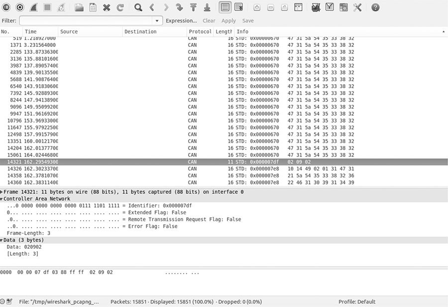
Figure 5-1: Wireshark on the CAN bus
Using candump
As with Wireshark, candump doesn’t decode the data for you; that job is left up to you, as the reverse engineer. Listing 5-1 uses slcan0 as the sniffer device.
$ candump slcan0
slcan0➊ 388➋ [2]➌ 01 10➍
slcan0 110 [8] 00 00 00 00 00 00 00 00
slcan0 120 [8] F2 89 63 20 03 20 03 20
slcan0 320 [8] 20 04 00 00 00 00 00 00
slcan0 128 [3] A1 00 02
slcan0 7DF [3] 02 09 02
slcan0 7E8 [8] 10 14 49 02 01 31 47 31
slcan0 110 [8] 00 00 00 00 00 00 00 00
slcan0 120 [8] F2 89 63 20 03 20 03 20
slcan0 410 [8] 20 00 00 00 00 00 00 00
slcan0 128 [3] A2 00 01
slcan0 380 [8] 02 02 00 00 E0 00 7E 0E
slcan0 388 [2] 01 10
slcan0 128 [3] A3 00 00
slcan0 110 [8] 00 00 00 00 00 00 00 00
slcan0 120 [8] F2 89 63 20 03 20 03 20
slcan0 520 [8] 00 00 04 00 00 00 00 00
slcan0 128 [3] A0 00 03
slcan0 380 [8] 02 02 00 00 E0 00 7F 0D
slcan0 388 [2] 01 10
slcan0 110 [8] 00 00 00 00 00 00 00 00
slcan0 120 [8] F2 89 63 20 03 20 03 20
slcan0 128 [3] A1 00 02
slcan0 110 [8] 00 00 00 00 00 00 00 00
slcan0 120 [8] F2 89 63 20 03 20 03 20
slcan0 128 [3] A2 00 01
slcan0 380 [8] 02 02 00 00 E0 00 7C 00
Listing 5-1: candump of traffic streaming through a CAN bus
The columns are broken down to show the sniffer device ➊, the arbitration ID ➋, the size of the CAN packet ➌, and the CAN data itself ➍. Now you have some captured packets, but they aren’t the easiest to read. We’ll use filters to help identify the packets we want to analyze in more detail.
Grouping Streamed Data from the CAN Bus
Devices on a CAN network are noisy, often pulsing at set intervals or when triggered by an event, such as a door unlocking. This noise can make it futile to stream data from a CAN network without a filter. Good CAN sniffer software will group changes to packets in a data stream based on their arbitration ID, highlighting only the portions of data that have changed since the last time the packet was seen. Grouping packets in this way makes it easier to spot changes that result directly from vehicle manipulation, allowing you to actively monitor the tool’s sniffing section and watch for color changes that correlate to physical changes. For example, if each time you unlock a door you see the same byte change in the data stream, you know that you’ve probably identified at least the byte that controls the door-unlocking functions.
Grouping Packets with cansniffer
The cansniffer command line tool groups the packets by arbitration ID and highlights the bytes that have changed since the last time the sniffer looked at that ID. For example, Figure 5-2 shows the result of running cansniffer on the device slcan0.
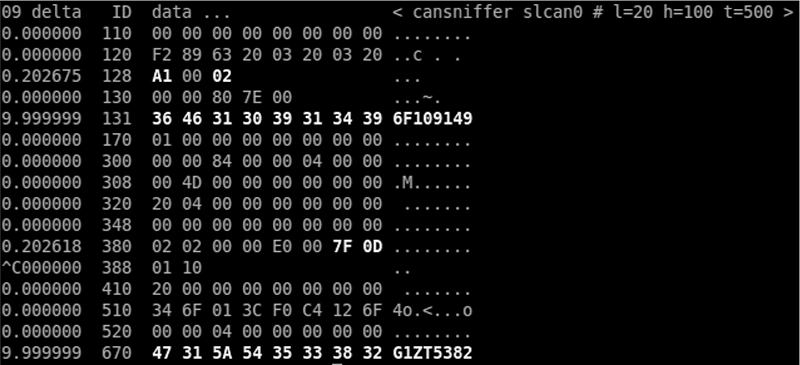
Figure 5-2: cansniffer example output
You can add the -c flag to colorize any changing bytes.
$ cansniffer -c slcan0
The cansniffer tool can also remove repeating CAN traffic that isn’t changing, thereby reducing the number of packets you need to watch.
Filtering the Packets Display
One advantage of cansniffer is that you can send it keyboard input to filter results as they’re displayed in the terminal. (Note that you won’t see the commands you enter while cansniffer is outputting results.) For example, to see only IDs 301 and 308 as cansniffer collects packets, enter this:
-000000
+301
+308
Entering -000000 turns off all packets, and entering +301 and +308 filters out all except IDs 301 and 308.
The -000000 command uses a bitmask, which does a bit-level comparison against the arbitration ID. Any binary value of 1 used in a mask is a bit that has to be true, while a binary value of 0 is a wildcard that can match anything. A bitmask of all 0s tells cansniffer to match any arbitration ID. The minus sign (-) in front of the bitmask removes all matching bits, which is every packet.
You can also use a filter and a bitmask with cansniffer to grab a range of IDs. For example, the following command adds the IDs from 500 through 5FF to the display, where 500 is the ID applied to the bitmask of 700 to define the range we’re interested in.
+500700
To display all IDs of 5XX, you’d use the following binary representation:
ID Binary Representation
500 101 0000 0000
700 111 0000 0000
------------------
101 XXXX XXXX
5 X X
You could specify F00 instead of 700, but because the arbitration ID is made up of only 3 bits, a 7 is all that’s required.
Using 7FF as a mask is the same as not specifying a bitmask for an ID. For example
+3017FF
is the same as
+301
This mask uses binary math and performs an AND operation on the two numbers, 0x301 and 0x7FF:
ID Binary Representation
301 011 0000 0001
7FF 111 1111 1111
______________________________
011 0000 0001
3 0 1
For those not familiar with AND operations, each binary bit is compared, and if both are a 1 then the output is a 1. For instance, 1 AND 1 = 1, while 1 AND 0 = 0.
If you prefer to have a GUI interface, Kayak, which we discussed in “Kayak” on page 46, is a CAN bus-monitoring application that also uses socketcand and will colorize its display of capture packets. Kayak won’t remove repeating packets the way cansniffer does, but it offers a few unique capabilities that you can’t easily get on the command line, such as documenting the identified packets in XML (.kcd files), which can be used by Kayak to display virtual instrument clusters and map data (see Figure 5-3).
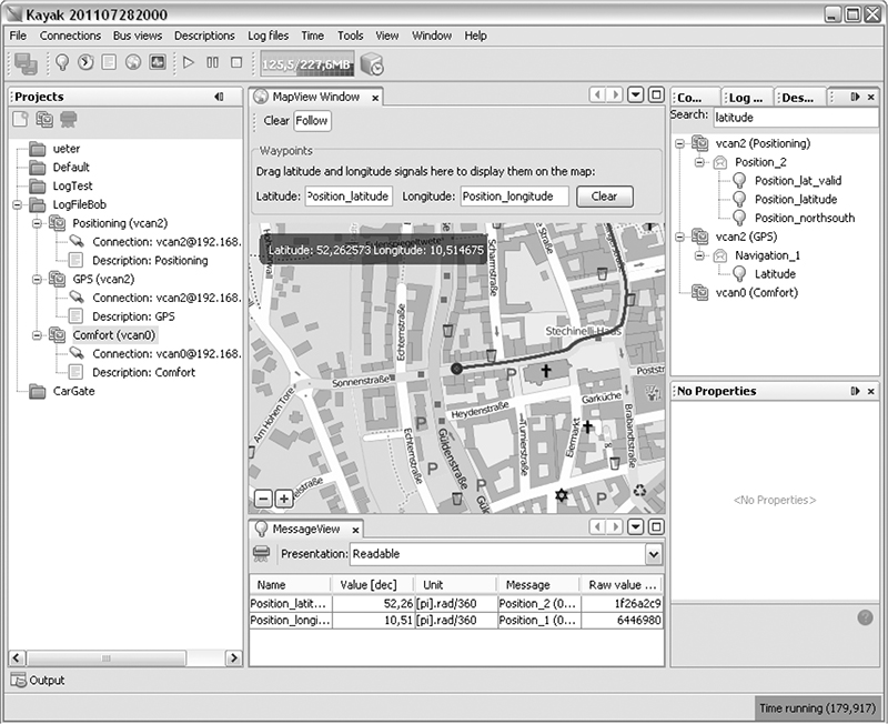
Figure 5-3: Kayak GUI interface
Using Record and Playback
Once you’ve used cansniffer or a similar tool to identify certain packets to focus on, the next step is to record and play back packets so you can analyze them. We’ll look at two different tools to do this: can-utils and Kayak. They have similar functionality, and your choice of tool will depend on what you’re working on and your interface preferences.
The can-utils suite records CAN packets using a simple ASCII format, which you can view with a simple text editor, and most of its tools support this format for both recording and playback. For example, you can record with candump, redirect standard output or use the command line options to record to a file, and then use canplayer to play back recordings.
Figure 5-4 shows a view of the layout of Kayak’s equivalent to cansniffer.
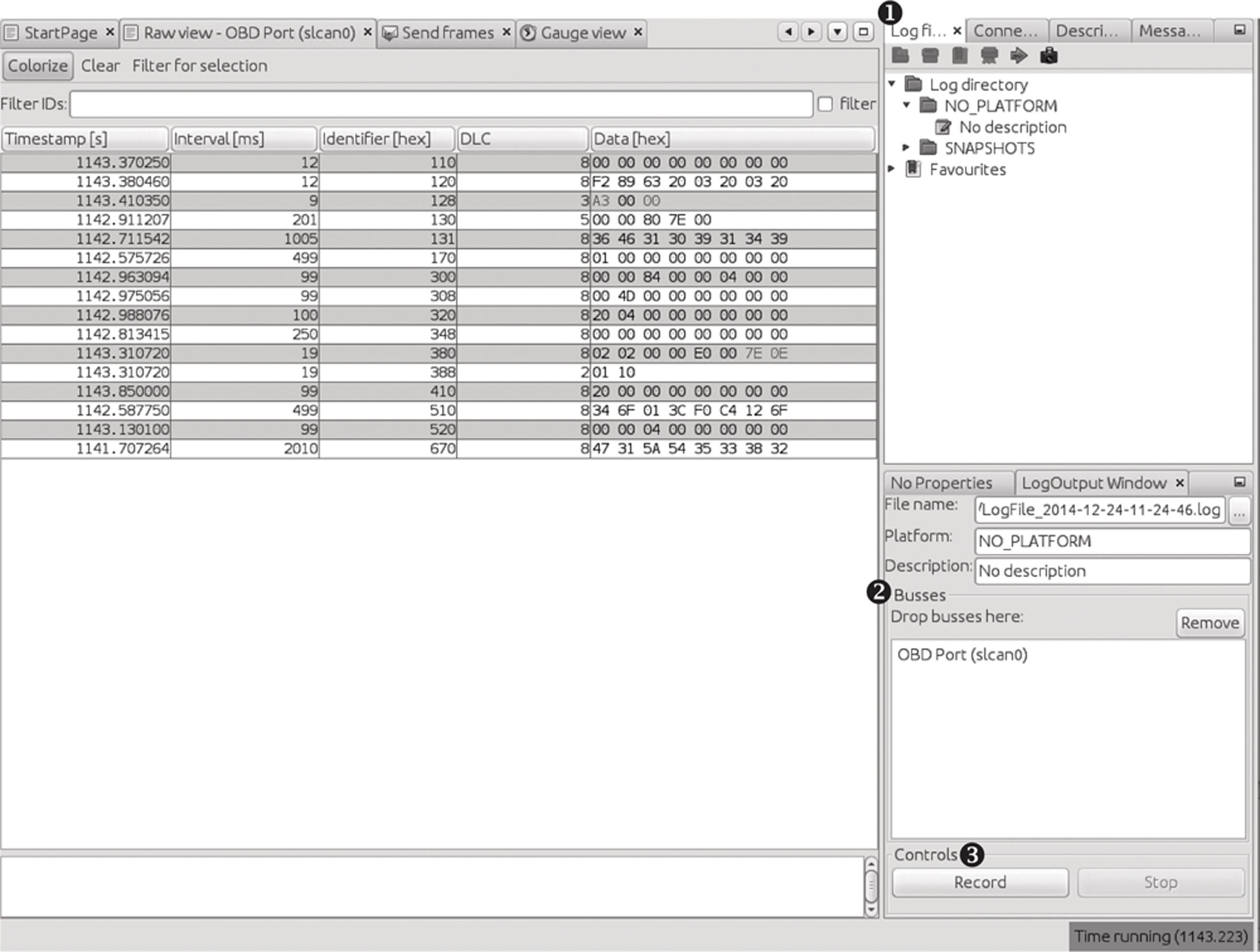
Figure 5-4: Kayak recording to a logfile
To record CAN packets with Kayak, first click the Play button in the Log files tab ➊. Then drag one or more buses from the Projects pane to the Busses field of the LogOutput Window tab ➋. Press the Record and Stop buttons at the bottom of the LogOutput window ➌ to start or stop recording. Once your packet capture is complete, the logging should show in the Log Directory drop-down menu (see Figure 5-5).
If you open a Kayak logfile, you’ll see something like the code snippet in Listing 5-2. The values in this example won’t directly correlate to those in Figure 5-4 because the GUI groups by ID, as in cansniffer, but the log is sequential, as in candump.
PLATFORM NO_PLATFORM
DESCRIPTION "No description"
DEVICE_ALIAS OBD Port slcan0
(1094.141850)➊ slcan0➋ 128#a20001➌
(1094.141863) slcan0 380#02020000e0007e0e
(1094.141865) slcan0 388#0110
(1094.144851) slcan0 110#0000000000000000
(1094.144857) slcan0 120#f289632003200320
Listing 5-2: Contents of Kayak’s logfile
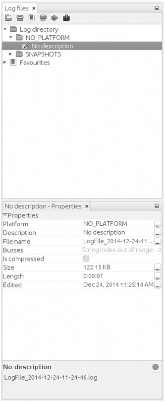
Figure 5-5: Right pane of Log files tab settings
Other than some metadata (PLATFORM, DESCRIPTION, and DEVICE_ALIAS), the log is pretty much the same as the one captured by the can-utils package: ➊ is the timestamp, ➋ is your bus, and ➌ is your arbitration ID and data separated by a # symbol. To play back the capture, right-click the Log Description in the right panel, and open the recording (see Figure 5-5).
Listing 5-3 shows the logfile created by candump using the -l command line option:
(1442245115.027238) slcan0 166#D0320018
(1442245115.028348) slcan0 158#0000000000000019
(1442245115.028370) slcan0 161#000005500108001C
(1442245115.028377) slcan0 191#010010A141000B
Listing 5-3: candump logfile
Notice in Listing 5-3 that the candump logfiles are almost identical to those displayed by Kayak in Figure 5-4. (For more details on different can-utils programs, see “The CAN Utilities Suite” on page 41.)
Creative Packet Analysis
Now that we’ve captured packets, it’s time to determine what each packet does so we can use it to unlock things or exploit the CAN bus. Let’s start with a simple action that’ll most likely toggle only a single bit—the code to unlock the doors—and see whether we can find the packet that controls that behavior.
Using Kayak to Find the Door-Unlock Control
There’s a ton of noise on the CAN bus, so finding a single-bit change can be very difficult, even with a good sniffer. But here’s a universal way to identify the function of a single CAN packet:
1. Press Record.
2. Perform the physical action, such as unlocking a door.
3. Stop Record.
4. Press Playback.
5. See whether the action was repeated. For example, did the door unlock?
If pressing Playback didn’t unlock the door, a couple of things may have gone wrong. First, you may have missed the action in the recording, so try recording and performing the action again. If you still can’t seem to record and replay the action, the message is probably hardwired to the physical lock button, as is often the case with the driver’s-side door lock. Try unlocking the passenger door instead while recording. If that still doesn’t work, the message for the unlock action is either on a CAN bus other than the one you’re monitoring—you’ll need to find the correct one—or the playback may have caused a collision, resulting in the packet being stomped on. Try to replay the recording a few times to make sure the playback is working.
Once you have a recording that performs the desired action, use the method shown in Figure 5-6 to filter out the noise and locate the exact packet and bits that are used to unlock the door via the CAN bus.
Now, keep halving the size of the packet capture until you’re down to only one packet, at which point you should be able figure out which bit or bits are used to unlock the door. The quickest way to do this is to open your sniffer and filter on the arbitration ID you singled out. Unlock the door, and the bit or byte that changed should highlight. Now, try to unlock the car’s back doors, and see how the bytes change. You should be able to tell exactly which bit must be changed in order to unlock each door.
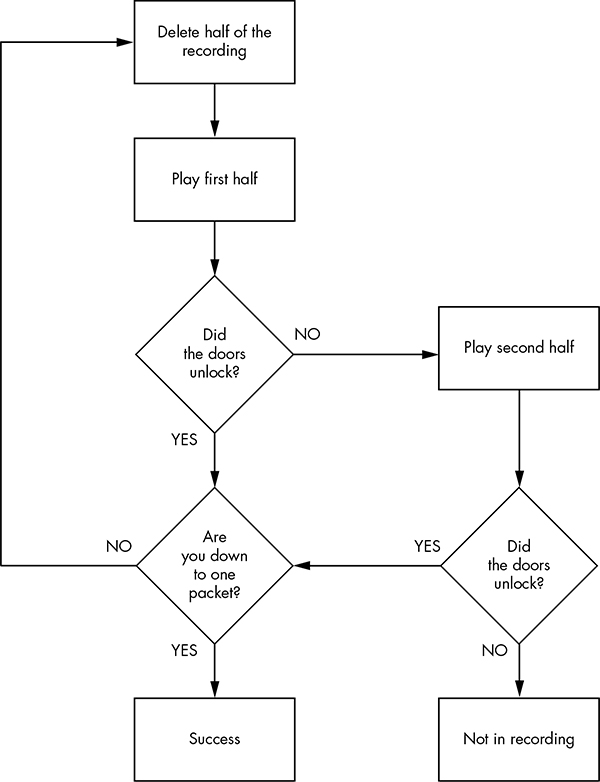
Figure 5-6: Sample unlock reversing flow
Using can-utils to Find the Door-Unlock Control
To identify packets via can-utils, you’d use candump to record and canplayer to play back the logfile, as noted earlier. Then, you’d use a text editor to whittle down the file before playback. Once you’re down to one packet, you can then determine which byte or bits control the targeted operation with the help of cansend. For instance, by removing different halves of a logfile, you can identify the one ID that triggers the door to unlock:
slcan0 300 [8] 00 00 84 00 00 0F 00 00
Now, you could edit each byte and play back the line, or you could use cansniffer with a filter of +300 to single out just the 300 arbitration ID and monitor which byte changes when you unlock the door. For example, if the byte that controls the door unlock is the sixth byte—0x0F in the preceding example—we know that when the sixth byte is 0x00, the doors unlock, and when it’s 0x0F, the doors lock.
NOTE
This is a hypothetical example that assumes we’ve performed all the steps listed earlier in this chapter to identify this particular byte. The specifics will vary for each vehicle.
We can verify our findings with cansend:
$ cansend slcan0 300#00008400000F0000
If, after sending this, all the doors lock, we’ve successfully identified which packets control the door unlock.
Now, what happens when you change the 0x0F? To find out, unlock the car and this time send a 0x01:
$ cansend slcan0 300#0000840000010000
Observe that only the driver’s-side door locks and the rest stay open. If you repeat this process with a 0x02, only the front passenger’s-side door locks. When you repeat again with a 0x03, both the driver’s-side door and the front passenger’s-side door lock. But why did 0x03 control two doors and not a different third door? The answer may make more sense when you look at the binary representation:
0x00 = 00000000
0x01 = 00000001
0x02 = 00000010
0x03 = 00000011
The first bit represents the driver’s-side door, and the second represents the front passenger’s-side door. When the bit is a 1, the door locks, and when it’s a 0, it unlocks. When you send an 0x0F, you’re setting all bits that could affect the door lock to a binary 1, thereby locking all doors:
0x0F = 00001111
What about the remaining four bits? The best way to find out what they do is to simply set them to 1 and monitor the vehicle for changes. We already know that at least some of the 0x300 signal relates to doors, so it’s fairly safe to assume the other four bits will, too. If not, they might control different door-like behavior, such as unlatching the trunk.
NOTE
If you don’t get a response when you toggle a bit, it may not be used at all and may simply be reserved.
Getting the Tachometer Reading
Obtaining information on the tachometer (the vehicle’s speed) can be achieved in the same way as unlocking the doors. The diagnostic codes report the speed of a vehicle, but they can’t be used to set how the speed displays (and what fun is that?), so we need to find out what the vehicle is using to control the readings on the instrument cluster (IC).
To save space, the RPM values won’t display as a hex equivalent of the reading; instead, the value is shifted such that 1000 RPM may look like 0xFA0. This value is often referred to as “shifted” because in the code, the developers use bit shifting to perform the equivalent of multiplying or dividing. For the UDS protocol, this value is actually as follows:
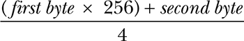
To make matters worse, you can’t monitor CAN traffic and query the diagnostic RPM to look for changing values at the same time. This is because vehicles often compress the RPM value using a proprietary method. Although the diagnostic values are set, they aren’t the actual packets and values that the vehicle is using, so we need to find the real value by reversing the raw CAN packets. (Be sure to put the car in park before you do this, and even lift the vehicle off the ground or put it on rollers first to avoid it starting suddenly and crushing you.)
Follow the same steps that you used to find the door unlock control:
1. Press Record.
2. Press the gas pedal.
3. Stop Record.
4. Press Playback.
5. See whether the tachometer gauge has moved.
You’ll probably find that a lot of engine lights flash and go crazy during this test because this packet is doing a lot more than just unlocking the car door. Ignore all the blinking warning lights, and follow the flowchart shown in Figure 5-6 to find the arbitration ID that causes the tachometer to change. You’ll have a much higher chance of collisions this time than when trying to find the bit to unlock the doors because there’s a lot more going on. Consequently, you may have to play and record more traffic than before. (Remember the value conversions mentioned earlier, and keep in mind that more than one byte in this arbitration ID will probably control the reported speed.)
Putting Kayak to Work
To make things a bit easier, we’ll use Kayak’s GUI instead of can-utils to find the arbitration IDs that control the tachometer. Again, make sure that the car is immobilized in an open area, with the emergency brake on, and maybe even up on blocks or rollers. Start recording and give the engine a good rev. Then, stop recording and play back the data. The RPM gauge should move; if it doesn’t, you may be on the wrong bus and will need to locate the correct bus, as described earlier in this chapter.
Once you have the reaction you expect from the vehicle, repeat the halving process used to find the door unlock, with some additional Kayak options.
Kayak’s playback interface lets you set the playback to loop infinitely and, more importantly, set the “in” and “out” packets (see Figure 5-7). The slider represents the number of packets captured. Use the slider to pick which packet you start and stop with during playback. You can quickly jump to the middle or other sections of the recording using the slider, which makes playing back half of a section very easy.
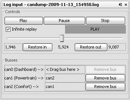
Figure 5-7: Kayak playback interface
As for testing, you won’t be able to send only a single packet as you did when you tried to unlock the car because the vehicle is constantly reporting its current speed. To override this noise, you need to talk even faster than the normal communication to avoid colliding all the time. For instance, if you play your packets right after the real packet plays, then the last seen update will be the modified one. Reducing noise on the bus results in fewer collisions and cleaner demos. If you can send your fake packet immediately after the real packet, you often get better results than you would by simply flooding the bus.
To send packets continuously with can-utils, you can use a while loop with cansend or cangen. (When using Kayak’s Send Frame dialog to transmit packets, make sure to check the Interval box.)
Creating Background Noise with the Instrument Cluster Simulator
The instrument cluster simulator (ICSim) is one of the most useful tools to come out of Open Garages, a group that fosters open collaboration between mechanics, performance tuners, and security researchers (see Appendix A). ICSim is a software utility designed to produce a few key CAN signals in order to provide a lot of seemingly “normal” background CAN noise—essentially, it’s designed to let you practice CAN bus reversing without having to tinker around with your car. (ICSim is Linux only because it relies on the virtual CAN devices.) The methods you’ll learn playing with ICSim will directly translate to your target vehicles. ICSim was designed as a safe way to familiarize yourself with CAN reversing so that the transition to an actual vehicle is as seamless as possible.
Setting Up the ICSim
Grab the source code for the ICSim from https://github.com/zombieCraig/ICSim and follow the README file supplied with the download to compile the software. Before you run ICSim, you should find a sample script in the README called setup_vcan.sh that you can run to set up a vcan0 interface for the ICSim to use.
ICSim comes with two components, icsim and controls, which talk to each other over a CAN bus. To use ICSim, first load the instrument cluster to the vcan device like this:
$ ./icsim vcan0
In response, you should see the ICSim instrument cluster with turn signals, a speedometer, and a picture of a car, which will be used to show the car doors locking and unlocking (see Figure 5-8).
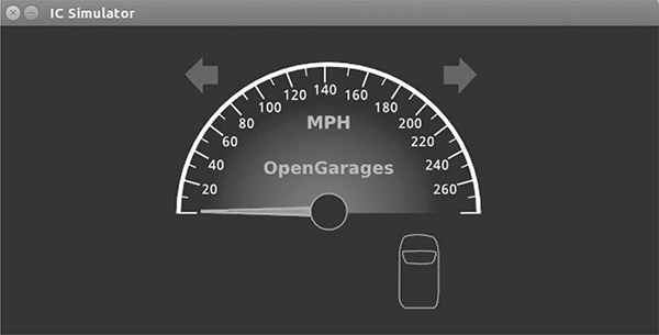
Figure 5-8: ICSim instrument cluster
The icsim application listens only for CAN signals, so when the ICSim first loads, you shouldn’t see any activity. In order to control the simulator, load the CANBus Control Panel like this:
$ ./controls vcan0
The CANBus Control Panel shown in Figure 5-9 should appear.
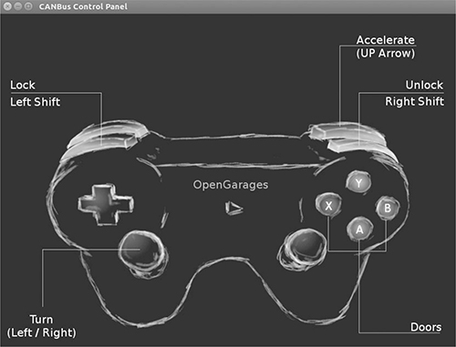
Figure 5-9: ICSim control interface
The screen looks like a game controller; in fact, you can plug in a USB game controller, and it should be supported by ICSim. (As of this writing, you can use sixad tools to connect a PS3 controller over Bluetooth as well.) You can use the controller to operate the ICSim in a method similar to driving a car using a gaming console, or you can control it by pressing the corresponding keys on your keyboard (see Figure 5-9).
NOTE
Once the control panel is loaded, you should see the speedometer idle just above 0 mph. If the needle is jiggling a bit, you know it’s working. The control application writes only to the CAN bus and has no other way to communicate with the icsim. The only way to control the virtual car is through the CAN.
The main controls on the CANBus Control Panel are as follows:
Accelerate (up arrow) Press this to make the speedometer go faster. The longer you hold the key down, the faster the virtual vehicle goes.
Turn (left/right arrows) Hold down a turn direction to blink the turn signals.
Lock (left SHIFT), Unlock (right SHIFT) This one requires you to press two buttons at once. Hold down the left SHIFT and press a button (A, B, X, or Y) to lock a corresponding door. Hold down the right SHIFT and press one of the buttons to unlock a door. If you hold down left SHIFT and then press right SHIFT, it will unlock all the doors. If you hold down right SHIFT and press left SHIFT, you’ll lock all the doors.
Make sure you can fit both the ICSim and the CANBus Control Panel on the same screen so that you can see how they influence each other. Then, select the control panel so that it’s ready to receive input. Play around with the controls to make sure that the ICSim is responding properly. If you don’t see a response to your controls, ensure that the ICSim control window is selected and active.
Reading CAN Bus Traffic on the ICSim
When you’re sure everything is working, fire up your sniffer of choice and take a look at the CAN bus traffic, as shown in Figure 5-10. Try to identify which packets control the vehicle, and create scripts to control ICSim without using the control panel.
Most of the changing data you see in Figure 5-10 is caused by a replay file of a real CAN bus. You’ll have to sort through the messages to determine the proper packets. All methods of replay and packet sending will work with ICSim, so you can validate your findings.
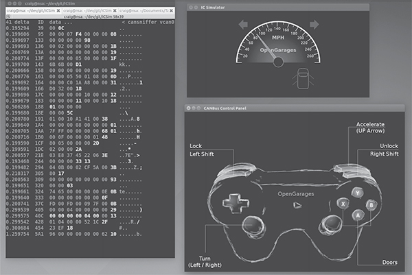
Figure 5-10: Screen layout for using ICSim
Changing the Difficulty of ICSim
One of the great things about ICSim is that you can challenge yourself by making it harder to find the target CAN traffic. ICSim supports four difficulty levels—0 through 3, with level 1 as the default. Level 0 is a super simple CAN packet that does the intended operation without any background noise, while level 3 randomizes all the bytes in the packet as well. To have the simulator choose different IDs and target byte positions, use ICSim’s randomize option:
$ ./icsim -r vcan0
Using CAN interface vcan0
Seed: 1419525427
This option prints a randomized seed value to the console screen.
Pass this value into the CANBus Control Panel along with your choice of difficulty level:
$ ./controls -s 1419525427 -l 3 vcan0
You can replay or share a specific seed value as well. If you find one you like or if you want to race your friends to see who can decipher the packets first, launch ICSim with a set seed value like this:
$ ./icsim -s 1419525427 vcan0
Next, launch the CANBus Control Panel using the same seed value to sync up the randomized control panel to the ICSim. If the seed values aren’t the same, they won’t be able to communicate.
It may take you a while to locate the proper packets the first time using ICSim, but after a few passes, you should be able to quickly identify which packets are your targets.
Try to complete the following challenges in ICSim:
1. Create “hazard lights.” Make both turn signals blink at the same time.
2. Create a command that locks only the back two doors.
3. Set the speedometer as close as possible to 220 mph.
Reversing the CAN Bus with OpenXC
Depending on your vehicle, one solution to reverse engineering the CAN bus is OpenXC, an open hardware and software standard that translates proprietary CAN protocols into an easy-to-read format. The OpenXC initiative was spearheaded by the Ford Motor Company—and as I write this, OpenXC is supported only by Ford—but it could work with any auto manufacturer that supports it. (Visit http://openxcplatform.com/ for information on how to acquire a pre-made dongle.)
Ideally, open standards for CAN data such as OpenXC will remove the need for many applications to reverse engineer CAN traffic. If the rest of the automotive industry were to agree on a standard that defines how their vehicles work, it would greatly improve a car owner’s ability to tinker and build on new innovative tools.
Translating CAN Bus Messages
If a vehicle supports OpenXC, you can plug a vehicle interface (VI) in to the CAN bus, and the VI should translate the proprietary CAN messages and send them to your PC so you can read the supported packets without having to reverse them. In theory, OpenXC should allow access to any CAN packet via a standard API. This access could be read-only or allow you to transmit packets. If more auto manufacturers eventually support OpenXC, it could provide third-party tools with more raw access to a vehicle than they would have with standard UDS diagnostic commands.
NOTE
OpenXC supports Python and Android and includes tools such as openxc-dump to display CAN activity.
The fields from OpenXC’s default API are as follows:
✵ accelerator_pedal_position
✵ brake_pedal_status
✵ button_event (typically steering wheel buttons)
✵ door_status
✵ engine_speed
✵ fuel_consumed_since_last_restart
✵ fuel_level
✵ headlamp_status
✵ high_beam_status
✵ ignition_status
✵ latitude
✵ longitude
✵ odometer
✵ parking_brake_status
✵ steering_wheel_angle
✵ torque_at_transmission
✵ transmission_gear_position
✵ vehicle_speed
✵ windshield_wiper_status
Different vehicles may support different signals than the ones listed here or no signals at all.
OpenXC also supports JSON trace output for recording vehicle journey. JSON provides a common data format that’s easy for most other modern languages to consume, as shown in Listing 5-4.
{"metadata": {
"version": "v3.0",
"vehicle_interface_id": "7ABF",
"vehicle": {
"make": "Ford",
"model": "Mustang",
"trim": "V6 Premium",
"year": 2013
},
"description": "highway drive to work",
"driver_name": "TJ Giuli",
"vehicle_id": "17N1039247929"
}
Listing 5-4: Simple JSON file output
Notice how the metadata definitions in JSON make it fairly easy for both humans and a programming language to read and interpret. The above JSON listing is a definition file, so an API request would be even smaller. For example, when requesting the field steering_wheel_angle, the translated CAN packets would look like this:
{"timestamp": 1385133351.285525, "name": "steering_wheel_angle", "value": 45}
You can interface with the OpenXC with OBD like this:
$ openxc-diag -message-id 0x7df -mode 0x3
Writing to the CAN Bus
If you want to write back to the bus, you might be able to use something like the following line, which writes the steering wheel angle back to the vehicle, but you’ll find that the device will resend only a few messages to the CAN bus.
$ openxc-control write -name steering_wheel_angle -value 42.0
Technically, OpenXC supports raw CAN writes, too, like this:
$ openxc-control write -bus 1 -id 42 -data 0x1234
This brings us back from translated JSON to raw CAN hacking, as described earlier in this chapter. However, if you want to write an app or embedded graphical interface to only read and react to your vehicle and you own a new Ford, then this may be the quickest route to those goals.
Hacking OpenXC
If you’ve done the work to reverse the CAN signals, you can even make your own VI OpenXC firmware. Compiling your own firmware means you don’t have any limitations, so you can read and write whatever you want and even create “unsupported” signals. For example, you could create a signal for remote_engine_start and add it to your own firmware in order to provide a simple interface to start your car. Hooray, open source!
Consider a signal that represents engine_speed. Listing 5-5 will set a basic configuration to output the engine_speed signal. We’ll send RPM data with a 2-byte-long message ID 0x110 starting at the second byte.
{ "name" : "Test Bench",
"buses": {
"hs": {
"controller": 1,
"speed": 500000
}
},
"messages": {
"0x110": {
"name": "Acceleration",
"bus", "hs",
"signals": {
"engine_speed_signal": {
"generic_name": "engine_speed",
"bit_position": 8,
"bit_size": 16
}
}
}
}
}
Listing 5-5: Simple OpenXC config file to define engine_speed
The OpenXC config files that you want to modify are stored in JSON. First, we define the bus by creating a JSON file with a text editor. In the example, we create a JSON config for a signal on the high-speed bus running at 500Kbps.
Once you have the JSON config defined, use the following code to compile it into a CPP file that can be compiled into the firmware:
$ openxc-generate-firmware-code -message-set ./test-bench.json > signals.cpp
Then, recompile the VI firmware with these commands:
$ fab reference build
If all goes well, you should have a .bin file that can be uploaded to your OpenXC-compatible device. The default bus is set up in raw read/write mode that sets the firmware to a cautionary read-only mode by default, unless signals or a whole bus is set up to support writing. To set those up, when defining the bus, you can add raw_can_mode or raw_writable and set them to true.
By making your own config files for OpenXC, you can bypass the restrictions set up in prereleased firmware and support other vehicles besides Ford. Ideally, other manufacturers will begin to support OpenXC, but adoption has been slow, and the bus restrictions are so strict you’ll probably want to use custom firmware anyhow.
Fuzzing the CAN Bus
Fuzzing the CAN bus can be a good way to find undocumented diagnostic methods or functions. Fuzzing takes a random, shotgun-like approach to reversing. When fuzzing, you send random-ish data to an input and look for unexpected behavior, which in the case of a vehicle could be physical changes, such as IC messages, or component crashes, such as shutdowns or reboots.
The good news is that it’s easy to make a CAN fuzzer. The bad news is that it’s rarely useful. Useful packets are often part of a collection of packets used to cause a particular change, such as a diagnostic service that is active only after a successful security token has been passed to it, so it’s difficult to tell which packet to focus on when fuzzing. Also, some CAN packets are visible only from within a moving vehicle, which would be very dangerous. Nevertheless, don’t rule out fuzzing as a potential method of attack because you can sometimes use it to locate undocumented services or crashes to a target component you want to spoof.
Some sniffers support fuzzing directly—a feature usually found in the transmission section and represented by the tool’s ability to transmit packets with incrementing bytes in the data section. For example, in the case of SocketCAN, you can use cangen to generate random CAN traffic. Several other open source CAN sniffing solutions allow for easy scripting or programming with languages such as Python.
A good starting point for fuzzing is to look at the UDS commands, specifically the “undocumented” manufacturer commands. When fuzzing undocumented UDS modes, we typically look for any type of response from an unknown mode. For instance, when targeting the UDS diagnostics of the ECU, you might send random data to ID 0x7DF and get an error packet from an unexpected mode. If you use brute-forcing tools such as CaringCaribou, however, there are often cleaner ways of accomplishing the same thing, such as monitoring or reversing the diagnostic tools themselves.
Troubleshooting When Things Go Wrong
The CAN bus and its components are fault-tolerant, which limits the damage you can do when reversing the CAN bus. However, if you’re fuzzing the CAN bus or replaying a large amount of CAN data back on a live CAN bus network, things can go wrong. Here are a few common problems and solutions.
Flashing IC Lights
It’s common for the IC lights to flash when sending packets to the CAN bus, and you can usually reset them by restarting the vehicle. If restarting the vehicle still doesn’t fix the lights, try disconnecting and reconnecting the battery. If that still doesn’t fix the problem, make sure that your battery is properly charged since a low battery can also make the IC lights flash.
Car Not Turning On
If your car shuts off and won’t turn back on, it’s usually because you’ve drained the battery by working with the CAN bus while the car is not fully running. This can drain a battery much faster than you might think. To restart it, jump the vehicle with a spare battery.
If you’ve tried jumping the vehicle and it still won’t turn on, you may need to pull a fuse and plug it back in to restart the car. Locate the engine fuses in the car’s manual and begin by pulling the ones you most suspect are the culprits. The fuse probably isn’t blown, so just pull it out and put it back in to force the problem device to restart. The fuses you choose to pull will depend on your type of vehicle, but if your engine isn’t starting, you will want to locate major components to disconnect and check. Look for main fuses around major electronics. The fuses that control the headlamps probably are not the culprits. Use a process of elimination to determine the device that is causing the issue.
Car Not Turning Off
You might find that you’re unable to shut the car down. This is a bad, but fortunately rare, situation. First, check that you aren’t flooding the CAN bus with traffic; if you are, stop and disconnect from the CAN bus. If you’re already disconnected from the CAN bus and your car still won’t turn off, you’ll need to start pulling fuses until it does.
Vehicle Responding Recklessly
This will only occur if you’re injecting packets in a moving vehicle, which is a terrible idea and should never be done! If you must audit a vehicle while it’s wheels are moving, raise it off the ground or on rollers.
Bricking
Reverse engineering the CAN bus should never result in bricking—that is, breaking the vehicle so completely that it can do nothing. To brick a vehicle, you would need to mess around with the firmware, which would put the vehicle or component out of warranty and is done at your own risk.
Summary
In this chapter, you learned how to identify CAN wires from the jumble of wires under the dash, and how to use tools like cansniffer and Kayak to sniff traffic and identify what the different packets were doing. You also learned how to group CAN traffic to make changes easier to identify than they would be when using more traditional packet-sniffing tools, such as Wireshark.
You should now be able to look at CAN traffic and identify changing packets. Once you identify these packets, you can write programs to transmit them, create files for Kayak to define them, or create translators for OpenXC to make it easy to use dongles to interact with your vehicle. You now have all the tools you need to identify and control the components of your vehicle that run on CAN.